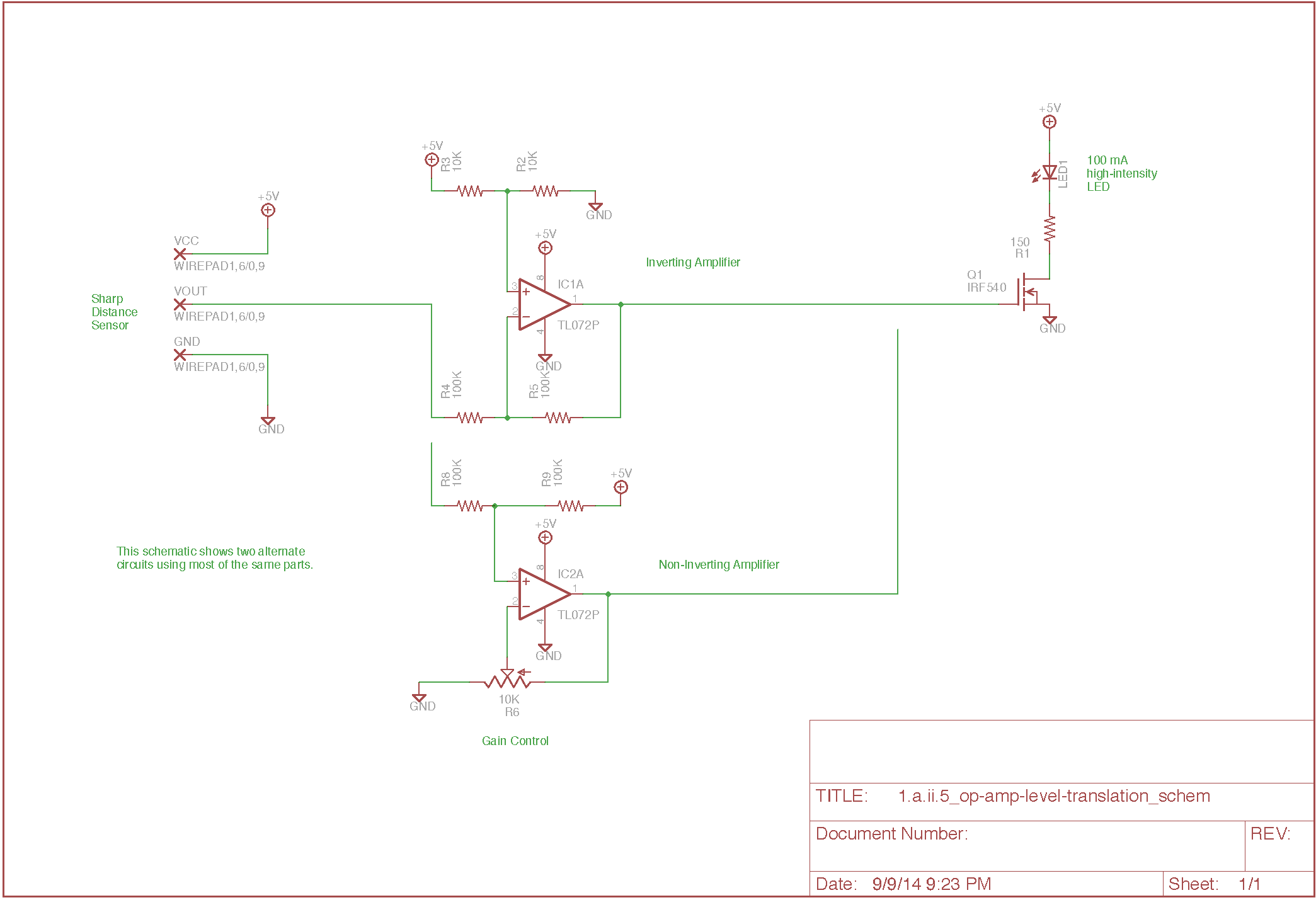
Use an op-amp circuit to match a sensor signal output to a driver signal input.
Many physical computing projects face the problem of translating an analog voltage from one range to another. For example, the Sharp range finders put out a signal from 0 to 3.0V, but the IRF540 MOSFET turn-on voltage is closer to 3.5-4.0V. An effective way to match one signal type to another is to add an amplifier stage which applies a gain and offset using a linear op-amp, short for “operational amplifier.” An op-amp is a basic building block for many kinds of linear circuits, including amplifiers, filters, oscillators, mixers, integrators, differentiators, etc. It can also be used to make non-linear circuits, such as a comparator or a Schmitt trigger. The reference guides below include many sample circuits.
Op-amps were originally constructed as modules of discrete components, but we will be using integrated circuit op-amps built on a single chip. The idealization of an op-amp is a differential amplifier with arbitrarily large gain: Vout = G * (V+ - V-), where G is infinite. The ideal op-amp has zero input current and infinite output voltage range. The infinite gain implies a simple heuristic, which is that for a negative-feedback circuit in equilibrium, the output must be at a voltage such that the inputs V+ and V- have equal voltage. Otherwise, even a tiny difference of input voltage would lead to an infinite output.
In practice, the op-amps we use have inputs with very high input impedance which draw essentially no current. The output is limited to a range within the supply voltages (the ‘rails’). The gain is quite high but not infinite. In practical circuits, the overall gain is set by constructing a resistor network which defines the relationship between the changes in the output and the changes in the input. If a large output voltage change is required at the output to maintain the equal-input equilibrium for a small change of input signal, then the signal will be amplified.
This exercise explores two basic amplifier circuits, an inverting amplifier and a non-inverting amplifier. Each uses four resistors to form two voltage dividers, one to control the gain and one for offset. In each case, the voltage divider between the output and the V- terminal controls the gain.
Many op-amp circuits are designed for a dual supply, meaning they assume the availability of matched positive and negative supplies centered around the zero ground voltage. However, it is more convenient for our purposes to just use a single supply, so some care may be required when using cookbook circuits.
We have the TL072P op-amp in stock, which includes two op-amps in an 8-pin package. The TL072 isn't designed for single-supply operation, so this part will be replaced with a 'rail-to-rail' part in a revised version of this exercise. For the time being, the circuit works but is sensitive to the gain and offset settings, as the op-amp output needs to stay within a range roughly between 1.3 and 4.0 Volts.
If you experiment, you can find the linear range of the MOSFET in which it is neither fully on or fully off.
