sntong-Project-07-Composition-with-Curves

sketch

//scarlet tong
//sntong@andrew.cmu.edu
// Section A
// Project 07 - Composition with Curves


//intitalize a value before using it for the x and y equations
var a = 0;

function setup() {
    createCanvas(300, 300);
    angleMode(DEGREES);
}

function draw(){
  //changing the alpha channel allows the movements of the dots to "lag" behind
  //creating interesting "tails" for each dot
  background(250,170,23,100);
  push();
  translate(150, height/2); // so that we can see the curve on the cancaus
  beginShape();
  for(var i = 0; i < 200; i++){
    var theta = map(i,0,100,0,360);
    // a controls how much the curve "bends" and loops
    var a = map(mouseX, 0,480,-7,7);
    //Conchoid of de Sluze equation from Wolfram MathWorld
    var x = (1/cos(theta)+(a*cos(theta)))*cos(theta);
    var y = (1/cos(theta)+(a*cos(theta)))*sin(theta);
    // color of the dots changes according to mouse position
    var col = map(mouseY, 0,300,0,255);
    var jitter = map(mouseY, 0,300,0,7);
    noStroke();
    fill(col);
    //"polar array" the Conchoid from the center
    rotate(90);
    //the first dotted line
    ellipse(x*20+random(0,1),y*20+random(0,1),2,2);
    //the second dots are rotated on a different angle of offset
    rotate(45);
    //the second dotted line
    fill(255-col);
    ellipse(-x*10+random(0,1),-y*10+random(0,1),2,2);
    // another layer of dots with larger diameters are then introduced to highlight
    //specific paths the curve took.
    if(i%4==0){
      ellipse(x*20+random(0,1),y*20+random(0,1),3,3)
    }
  }
  endShape(CLOSE);
  pop();

}

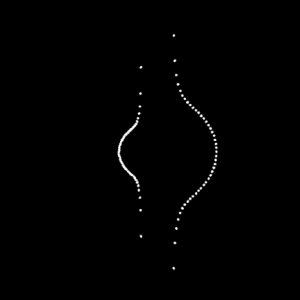
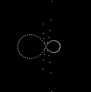
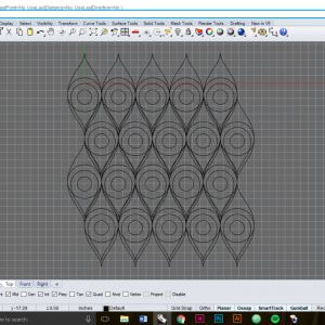
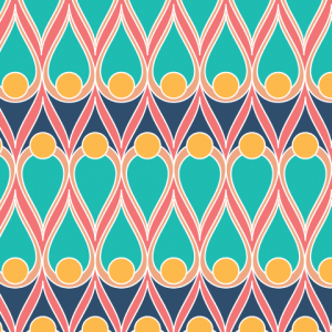
For this project I choose the to use the Conchoid of de Sluze equation found on Wolfram MathWorld as my base curve. I did more experimenting while I was coding and layer more alterations to the curve configuration each step. In this assignment I wanted to explore the use of density so that it implies a set of lines; however once the image is static it becomes harder to tell which dots make up a specific curve. I started off with a set of mirrored curves where one is scaled to a factor to another. Then I added motion of the curves by tracking mouseX and mouseY. From there color change is referred to mouse position and rotation is introduced to the curves.

sntong-LookingOutwards-07

Nicholas Rougeux is a self-taught digital artists who wanted to visualize and provide a new way music can be read, thus creating the project Off the Staff. With the help of some scripting by Peter Jonas from MuseScore that helped Nicholas to efficiently and accurately create the animation using the program NodeBox. His creative way of interpreting and reading music has introduced a new way for people to appreciate music and demonstrate its complexity, although in a very abstract way, to those who do not have a music background.

sntong-Project-06-Abstract-Clock

sketch

//Scarlet Tong
//sntong@andrew.cmu.edu
//Section A
// Project 06 - Abstract Clock


// center of the bacteria
var cx = 240;
var cy = 220;
//radius of the moving "dial" around the color ring
var dotR = 4;
// arrays used for color assignment for each hour on the color ring
var R = [234,225,141,115,242,225,214,238,243,42,98,125];
var G = [218,160,213,100,214,152,88,51,121,165,114,198];
var B = [133,60,230,115,185,146,128,85,105,141,100,127];
// angles used to divide the ring into 12 segements
var angles = [0,30,60,90,120,150,180,210,240,270,300,330];
var nVals = angles.length;

function setup() {
    createCanvas(480, 480);
    background(0);
}

function draw() {
  background(0);
  var Min = minute();
  // white petri dish background for the bacteria
  fill(255);
  ellipse(cx,cy,350,350);

// drawing the color rings that will indicate hour
  for (var i = 0; i < nVals; i++) {
    stroke(R[i],G[i],B[i]);
    strokeWeight(10);
    strokeCap(SQUARE);
    arc(cx,cy,350,350,angles[i]-105,angles[i+1]-105);
    push();
    translate(240,220);
    rotate(-90);
    var eX = cos(angles[i])*170;
    var eY = sin(angles[i])*170;
    ellipse(eX,eY,10,10);
    pop();
  }

// make bacteria rotate each minute
  push();
  translate(cx,cy);
  angleMode(DEGREES);
  var mappedMin = map(Min,0,60,0,360);
  rotate(mappedMin);
  bacteria();
  pop();

  // isolate the "seconds" dot and the text from other fill and stroke statements above
  push();
  dot();
  textAlign(CENTER);
  text("Specimen :  #",190,430);
  text(month(),240, 430);
  text("-" , 260,430);
  text(day(), 270,430);
  text("-", 280,430);
  text(year()-2000,295,430);
  pop();


}

//bacteria at the middle of the petri dish
function bacteria(){
  var H = hour();
  // introduce some jitter because bacteria are always moving
  var jitterX = random(-.8,.8);
  var jitterY = random (-.7,.7);

// body of the bacteria
  rectMode(CENTER);
  strokeWeight(5);
  stroke(0);
  strokeCap(ROUND);
  // because the color ring only has 12 colors, the hour() value must be converted to within 12 hrs.
  if (H <= 12) {
    Hr = hour();
  } if(H > 12) {
    Hr = hour()-12;
  }

// the color assignment corresponds to the color ring and hour it indicates
  fill(R[Hr],G[Hr],B[Hr],200);
  rect(0+jitterX,0+jitterY,50,150,25);

  // little legs around the bacteria
  line(0,-75,0+jitterX,-110); // minute hand for time
  line(-10,73+jitterY,-13,80);
  line(10+jitterX,73,13,85+jitterY);
  line(-25+jitterX,50,-35+jitterX,50);
  line(-25,-60+jitterY,-30+jitterX,-65);
  line(-18,-70+jitterY,-26,-80);
  line(18+jitterX,-70,20+jitterX,-73);
  line(25,-30+jitterY,30,-30);
  line(25,-40,34,-40+jitterY);

  // little dots inside the bacterias, the guts
  noStroke();
  fill(0);
  ellipse(10+jitterX,10+jitterY,dotR,dotR);
  ellipse(-10+jitterX,-40+jitterY,dotR,dotR);
  ellipse(5+jitterX,-30+jitterY,dotR,dotR);
  ellipse(-10+jitterX,40+jitterY,dotR,dotR);
  ellipse(5+jitterX,55+jitterY,dotR,dotR);
  ellipse(-5+jitterX,30+jitterY,dotR,dotR);
  ellipse(5+jitterX,-20+jitterY,dotR,dotR);
  ellipse(-6+jitterX,13+jitterY,dotR,dotR);
}

// small dot that act as the "dial" for a microscope
// moves along the ring per second
function dot(){
  var Sec = second();
  var mappedSec = map(Sec, 0,60, 0,360)-90;
  var x = cos(mappedSec)*150;
  var y = sin(mappedSec)*150;
  fill(200);
  noStroke();
  ellipse(cx+x,cy+y,10,10);
}

For this assignment I imagined as if we are viewing into a microscope to see a small bacteria that is moving around in the petri dish. The longest “leg” on the bacteria is the minute hand. The bacteria changes color according to the hour color that is found on the color ring. The specimen name is the listed as month/date/year, which completes this “clock”. I took a long time to figure out the small adjustments for each element to work together (i.e those extra 90 degree changes and shifting) and align in color, but small sketches and tables help me organize the data before I input them to arrays.

sntong-Looking-Outwards-06-Randomness

This image is by Catodo, which is the stage name of Enrico Zimuel who is a computational artist, sound designer and software developer from Turin (Italy). This particular work he analyzed the painting “The Garden of Earthly Delights” by Hieronymus Bosch, and using the “pointillism” technique, a pixel is selected at random and draws a triangle with random width to the color that corresponds to the original painting. Catodo proposes an interesting interpretation of classical arts and how we can start to read and understand the connection between computational art and classical arts.

sntong-Project-05-Wallpaper

sketch

//Scarlet Tong
//sntong@andrew.cmu.edu
//Section A
// Project 5: Wallpaper

//x and y coordinates the tip of the tear drops
var x = 0;
var y = 0;
// scale
var Large = 25;
var Medium = Large-1;
var Small = Large-5;
// for loop coordinates
var transY = 0;
var transX = 30;

function setup() {
    createCanvas(480, 480);
    background (243,117,117);//hot pink!
}

function draw() {
  //array the pattern on the odd rows
  for (var transY = 0; transY < width; transY+= Large*6+15) {
    for (var transX = 0; transX < width+30; transX+= Large*2+10) {
      pattern(transX,transY);
    }
  }
  // array the pattern for even rows and offset them so they fill the gap
  for (var transY = -Large*3-8; transY < width; transY+= Large*6+15) {
    for (var transX = Large+5; transX < width; transX+= Large*2+10) {
      pattern(transX,transY);
    }
  }
  noLoop();
}

function pattern(transX,transY){
  stroke(255);
  strokeWeight(1);
  //deep blue tear drop, aka large drop
  push();
  translate(transX,transY);
  fill(48,78,109,200);
  beginShape();
  curveVertex(x,y);
  curveVertex(x,y);
  curveVertex(Large,Large*3);
  curveVertex(x,Large*4);
  curveVertex(x-Large, y+Large*3);
  curveVertex(x,y);
  curveVertex(x,y);
  endShape();
  pop();
  //pale orange tear drop, medium drop
  push();
  translate(transX,transY+Large*6);
  fill(237,168,131,100);
  angleMode(DEGREES);
  rotate(180);
  beginShape();
  curveVertex(x,y);
  curveVertex(x,y);
  curveVertex(Medium,Medium*3);
  curveVertex(x,Medium*4);
  curveVertex(x-Medium, y+Medium*3);
  curveVertex(x,y);
  curveVertex(x,y);
  endShape();
  // teal tear drop, small drop
  fill(43,188,177,120);
  beginShape();
  curveVertex(x,y+10);
  curveVertex(x,y+10);
  curveVertex(Small,Small*3+10);
  curveVertex(x,Small*4+10);
  curveVertex(x-Small, y+Small*3+10);
  curveVertex(x,y+10);
  curveVertex(x,y+10);
  endShape();
  //yellow circle
  fill(253,185,74,200);
  ellipse(x,Small*5,Large,Large);
  //small dark blue circle on the tip of the shape
  fill(48,78,109);
  ellipse(0,0,10,10);
  pop();
}

I was inspired by the the features of a peacock when making this pattern. Using the tear drop shape as the base, I was able to rotate and scale the shape accordingly to generate the pattern before I array it to make the wallpaper using for loops and nested loops. I used Rhino to help me to generate the line work before going into Illustrator to add in the color. As I was coding I also played with the alpha channels to manipulate the opacity of the colors to see the layers of tear drops that make up the pattern.


sntong-LookingOutwards-05-3D-Comupter-Graphics

The Roots by elreviae is generated with 3Ds Max and photoshop. elreviae is a french digital artist and designer who started off with self-taught skills. For this piece, he is able to show the process of neurons communicating to each other. It even suggests how branches of network are crossing over or establishing communication through the circular medium in the center. It is fascinating to see technology being re imagined to be implemented in the human body for medical purposes. 

sntong-Project-04-String-Art

sketch

//scarlet Tong
//sntong@andrew.cmu.edu
//Section A
//Project-04-String-Art


//variables for y compment of guiding lines
var aLineX1 = 200;
var aLineX2 = 400;
var aLineY = 0;
// variable for x component of guiding lines
var bLineX = 100;
var bLineY1 = 0;
var bLineY2 = 350;

//color variables
var R = 255;
var G = 200;
var B =200;

function setup() {
    createCanvas(400, 300);
    background(0);

}

function draw() {
  //create invisible guiding lines that determines where the points are generated
  //each guiding line creatres 20 points
  for (var i = 0; i <= 1; i+= .05) {
    //guiding line 1
    var x1 = lerp(bLineY1,bLineX,i);
    var y1 = lerp(bLineY1,bLineY2,i);
    //guiding line 2
    var x2 = lerp(aLineX1,aLineX2,i);
    var y2 = lerp(aLineX1,aLineY,i+.01);
    //guiding line 3
    var x3 = lerp(bLineY2,bLineY1,i);
    var y3 = lerp(aLineX2,bLineY2,i);
    //first web has the color pink
    stroke(R,G,B);
    strokeWeight(.85);
    line(x1,y1,x2,y2);
    //second web is colored white
    stroke(B,R,G);
    strokeWeight(.5);
    line(x2,y2,x3,y3);
    }

    //add changing colors with respect for mouse location for fun 
    if (mouseX < width) {
      R = mouseX;
      G = mouseY;
      B = R-G;
    }
}

I explored using the lerp() function to help me generate “guiding” lines that will govern the shape of resulting “web”. Using for loop, I was able to generate 2 webs with 3 guiding lines for this composition. The color of the lines relate to the location of the mouse on the canvas (so the drawing appears and disappears as you interact with it with the mouse), and I struggled working out the location of the guiding lines and using variables to sort out the sequences of points when working on this project

sntong-LookingOutwards-04-Sound-Art

Table d’Harmonie is created by Pascal Broccolichi and using black corindon powder and speakers. When resonance is reached between the sound and the powder, the powder amasses into small mounts of circular craters around the speakers. The theory of “granular synthesis” is applied to help program the sound to create desired shapes. The project is interesting when trying to visualize sound in a physical form and translating something that has no visual cues into something physical through the medium of different materials.

sntong-Project-03-Dynamic-Drawing

sketch

//Scarlet Tong
//Sectiom A
//sntong@andrew.cmu.edu
//Project-03-Dynamic-Drawing

var column = 64;
var loc = 30;
var dim = 30;
var R = 254;
var G = 254;
var B = 254;
var angle = 0;
var angleVar = 40;
var dir = 8;
var colorGo = false;

function setup(){
  createCanvas(640,480);
  background(150);

}

function draw(){
  background (0);
  var w = 0;
  var h = 0;

  // basic grid of square
  push();
  translate(width/2,height/2);
  angleMode(DEGREES);
  noStroke();
  rectMode(CENTER);
  fill(254);
  rect(w, h, dim,dim);//center rect
  rotate(angle);
  fill(R,G,B);//color pair 1
  rect(w-loc,h-loc,dim,dim);//rect a1
  rect(w+loc,h+loc,dim,dim);//rect a8
  //color pair 2
  fill(R+loc,G,B);
  rect(w,h-loc,dim,dim);//rect a2
  rect(w-loc,h,dim,dim);//rect A4
  //color pair 3
  fill(R,G+loc,B);
  rect(w+loc,h-loc,dim,dim);//rect a3
  rect(w-loc,h+loc,dim,dim);//rect a6
  //color pair 4
  fill(R,G,B+loc);
  rect(w+loc,h,dim,dim);//rect A5
  rect(w,h+loc,dim,dim);//rect a7
  pop();

  stepOne();
  stepTwo();
  // this resets the value for angle to make sure the squares rotate when
  //the mouse is going back and forth the canvas
  if (mouseX < column*2 || mouseX > column*9) {
    angle = 0;
  }

  stepThree();
  //this to make sur the random color generation does not continue
  if (mouseX < column) {
    colorGo = false;
  }

}

function stepOne(){
  if (mouseX >= column & mouseX <= column+column/2 && mouseX <= column*3) {
    //Translation of the sqaures away from the center
    loc = max(50);
    loc += mouseX-70;
    //scale each square larger
    dim += mouseX-140;
    dim = max(50);
  }
}

//rotation of outter squares
function stepTwo (){
  //rotating the outside squares if mouseX is between a certain range
  if (mouseX > column*4 & mouseX < column*9 && angle < 90) {
    angle += angleVar*dir;
    R = random(0,254);
    G = random(0,254);
    B = random(0,254);
  } if (angle >= 90  & colorGo == false) {//to stop rotation exceeding 90 degrees
    angle = 90;
    colorGo = true;
  } else {
    angleVar = 0.2*dir;
  }
}
//Collsping and combining the squares to make large square
function stepThree(){
  if(mouseX > column*7 & mouseX < width){
    loc += mouseX-400;
    loc = min(50);
  }
}

I had fun trying to create a simple sequence of motion starting from the idea of generating a part to whole. A large square splits into smaller modules, and there is a variety of color and rotation that makes them all different from the “original” module that is located in the middle. I had to plan out the steps by using hand sketch diagrams.

sntong-Looking Outwards-03-Computational Fabrication

Evaporative Folding by Jeana Ripple (project architect), Ryan Lewandowski and Hossein Haj-Harriri + Mehdi Sadaat (consultant) uses computational techniques to customize the production of aluminum modules that creates an effective facade for evaporative cooling for houses in hot and dry climates. By optimizing material properties and manufacturing processes for aluminum, the team was able to generate an effective “cooling” facade that is durable, mold-resistant and can also act as an passive solar heat gain element during the night. The computational processes in the project is used to determine location, size of holes that are then CNC into the aluminium panels to create the perforation pattern suited for the house in the specific location.

It is inspiring to see the possible elegant solutions that computational processes are allowing architects and engineers to address environmental issues. Not only the project is successful in demonstrating what computational fabrication can do for the construction industry, it also shows that architects can design smarter buildings that are more energy efficient.

(image source: http://ripplearchitecture.com/Evaporative-Skin)