2.1.25. Exercise: Stepper Motor Knob
2.1.25.1. Objective
Control a stepper motor using a driver module.
A stepper motor uses a toothed rotor and multiple drive coils to create motion in discrete steps. The fundamental angular size of the steps is determined by the physical spacing of the internal magnetic teeth. Steppers motors are open-loop since there is no sensor involved in controlling position, the driver simply cycles the coil currents and assumes the motor moves synchronously. If the motor encounters too high a torque, the magnetic forces can be overcome and the rotor will slip to a different position. The microcontroller has have no means of detecting this error.
This exercise uses an stepper motor driver module which takes care of cycling the currents appropriately through the two coils of a bipolar stepper motor. The primary inputs to the driver are direction and step. The additional inputs control fractional stepping and the overall driver power state.
As a simple one-in one-out demonstration, the exercise uses a potentiometer as an analog position command control input.
2.1.25.2. Steps and observations
- Use a DMM to measure the winding resistance of the stepper motor. A bipolar stepper motor will have two independent windings which should be clearly observable as a low resistance between two separate wire pairs.
- The lab stocks several different kinds of stepper motors and stepper motor drivers. Please check the motor type; it should have a rated voltage lower than your supply voltage. These drivers control the current by chopping the power supply, so the supply voltage can be higher than the motor rating. If the chosen supply voltage is between 2.5-8V (e.g. 5V), you will need to use the low-voltage DRV8834 stepper motor driver. If the supply voltage is between 8-35V (e.g. 12V), you should use the A4988 stepper motor driver, which is a newer replacement for the A4983.
- You will need to set the current limiting potentiometer on the driver to the correct level for the stepper motor you have chosen. To set it, you will need to use a thin piece of plastic or small screwdriver to rotate the surface-mount potentiometer while measuring the voltage at the wiper pin with a DMM. The driver will need motor power applied for this to work. For the A4988, the voltage is Vref=Ilimit/2.5, for the DRV8834 the voltage is Vref=Ilimit/2.0. So for example, if using the NEMA14 SY35ST28-0504A stepper with 0.5A/Phase rating, with a A4988 the current limit reference voltage should be 0.2V, and for the NEMA14 SY35ST36-1004A with a 1.0A/phase rating, the voltage should be 0.4V.
- Load and run the KnobToStepperMotor sketch. (Note: there is a MotorKnob sketch included in the Arduino IDE which assumes the stepper motor is directly driven from the Arduino; instead we will use a modular driver for this exercise.)
- Observe the stepper motor motion.
- Try moving the MS1 pull-up resistor between 5V and GND and observing the resulting change in step rate. The driver is capable of microstepping in which the coils can be driven using PWM rather simply on or off in order to divide the fundamental step into smaller angles.
- Read the data sheet for the driver and configure the driver for even finer steps.
2.1.25.3. Comments
Stepper motors can move relatively fast but at too high a rate can lose count.
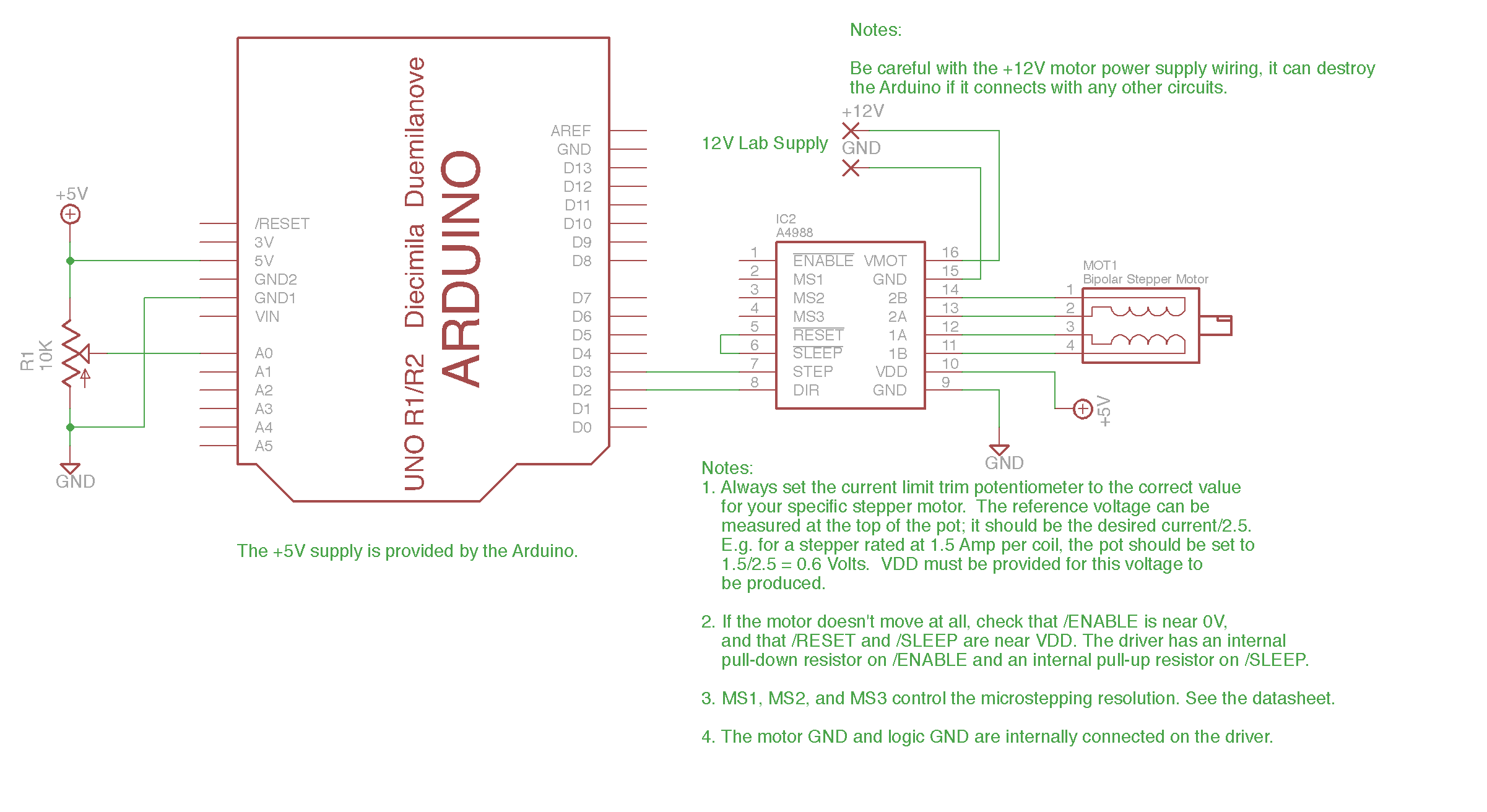
The schematic for the A4988 shows that the driver module is mostly a breakout board for the surface-mount driver chip, but includes the current reference pot, current-sensing resistors, pullup resistors, pulldown resistors, charge-pump capacitors, and decoupling capacitors which filter the power.
2.1.25.4. Figures
2.1.25.5. Arduino Sketch
2.1.25.6. Other Files
- EAGLE file:
stepper-motor-knob.sch
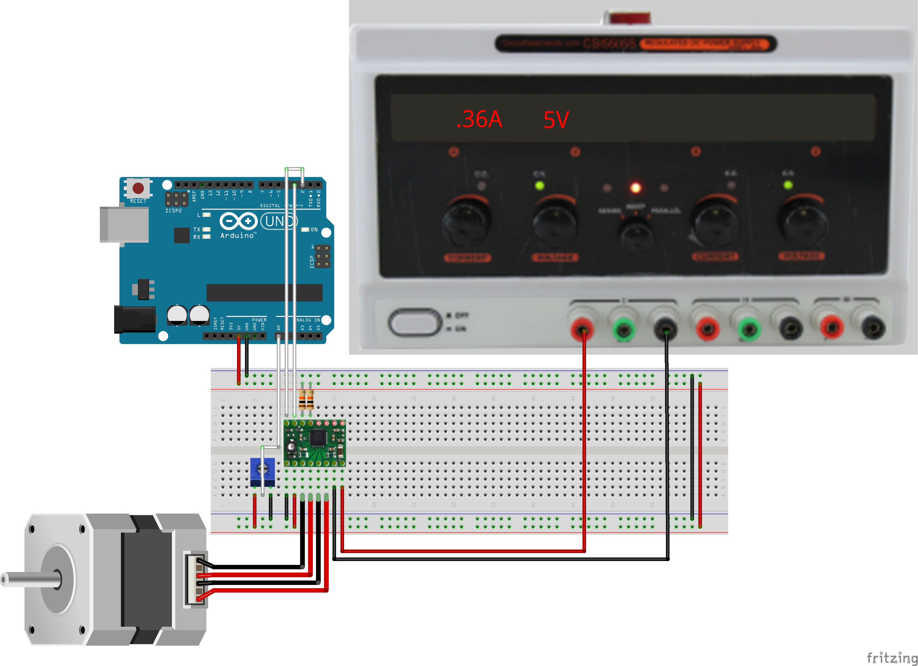
2.1.25.7. Obsolete Figures
This are somewhat misleading and will be removed soon, but are shown here for continuity.
- Fritzing file:
stepper-motor-knob.fzz