2.1.3. Exercise: Power Switch
2.1.3.1. Objective
Test a simple circuit on a breadboard.
We will use solderless breadboards a lot for prototyping circuits. The connection points accept component leads and solid wire. Each short row of five points is connected internally and is used for signal connections. The long rows along the edges are connected internally and are normally used for power distribution.
The easiest way to connect a bench supply to a breadboard is with solid core wire which can plug directly into the buss connections at top and bottom of the solderless breadboard. It’s a good habit to follow a consistent color code with red for positive and black for ground.
2.1.3.2. Steps and observations
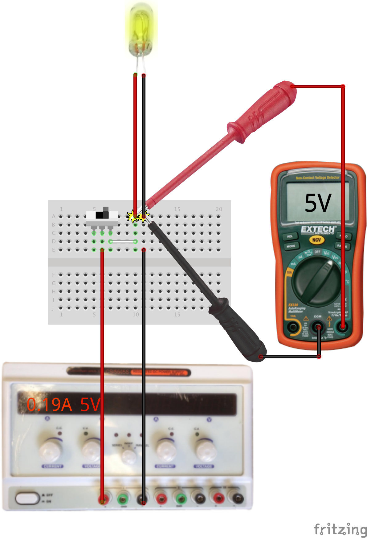
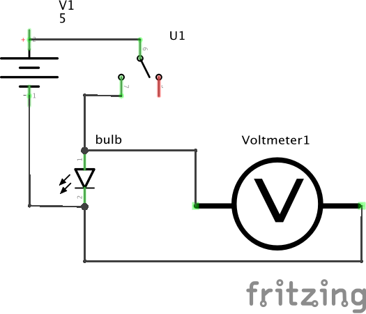
- Wire and test the circuit as shown with a switch and a bulb.
- Measure the voltage across the lamp in both on and off states. Voltage is measured between two points; the meter is placed in parallel with the lamp.
- Current is measured through a conductor; measuring the lamp current requires connecting the meter in series with the lamp by disconnecting either wire leading to the lamp and connecting the meter across the opened connection.
- Set the meter to DC current mode (mA) and move the positive probe to the connector for current.
- Open the lamp circuit, connect the meter in-circuit, and observe the current in both on and off states.
- The lamp acts as a resistor. What is the computed resistance in the on state? This can be calculated from the current measured for a given applied voltage.
2.1.3.3. Comments
The basic rules of current flow and voltage potentials in a circuit graph are captured by Kirchhoff’s circuit laws.
2.1.3.4. Other Files
- Fritzing file:
power-switch.fzz