2.1.15. Exercise: MOSFET Transistor Driver
2.1.15.1. Objective
Amplify a control signal using a MOSFET transistor.
A transistor is a type of three-terminal semiconductor component which allows a control current or voltage at the base or gate terminal to affect the current flowing through the device. A MOSFET is a particular type of transistor with very high current gain; the gate input has very high impedance, such that a gate voltage with very little current can control the current flowing between the source and drain. This makes it very convenient for interfacing logic-level signals to loads such as motors.
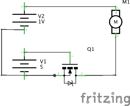
MOSFETs have a linear range in which the current is proportional to the gate voltage, but this exercise will use it in a saturation mode in which it is either on or off. MOSFETS come in both P-channel and N-channel varieties exhibiting different polarities; this exercise uses an N-channel MOSFET in which a small positive gate voltage relative to the source terminal will cause a positive current to flow from drain to source, activating the motor.
MOSFETs have very low forward voltage, i.e., the voltage drop across the source and drain can be very low, meaning there is very little power dissipated for a given current.
2.1.15.2. Steps and observations
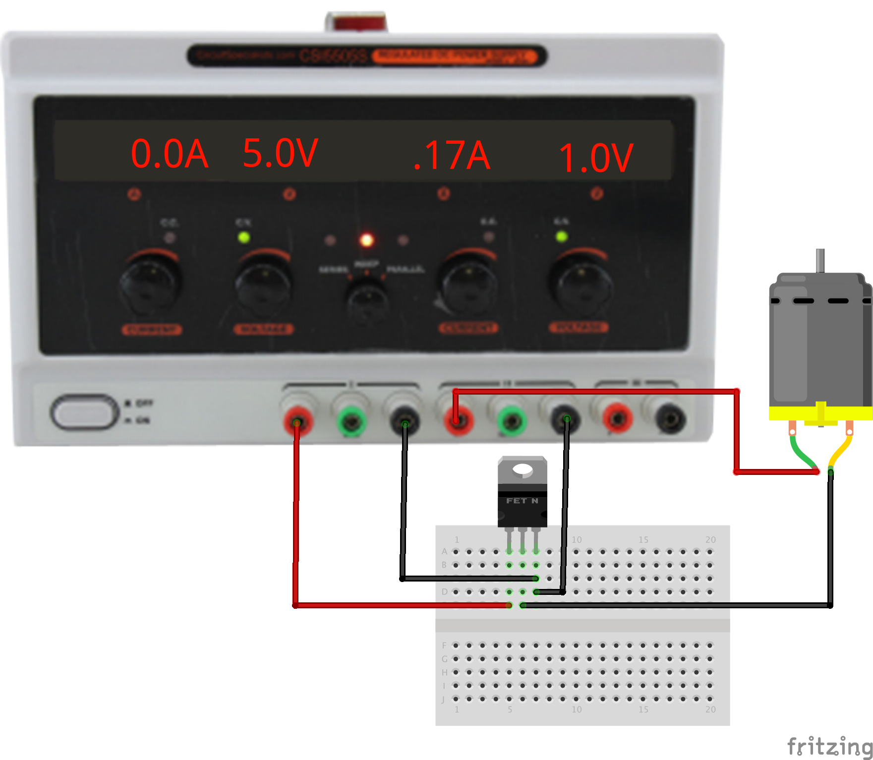
- Set the power supplies to the specified voltages first. We are using a low-voltage motor so the 1V is actually the ‘high-power’ energy supply and the 5V is the logic supply. The MOSFET can handle substantially higher currents than used by this motor.
- Manually connect and disconnect the gate voltage, observing the motor operation. If disconnecting the gate does not turn off the transistor, try grounding the gate. Even a small static charge on the gate can be enough to turn it on.
- Measure the gate current and resistance, and compute the power dissipated by the gate input. (It should be very low.)
- Measure the motor current, and compute the power dissipated by the motor.
- Compute the power gain of the amplifier: the output power divided by the input power.
2.1.15.3. Comments
Note that unlike the relay circuit, the input and output circuits are not isolated from each other.
MOSFETS are fast and silent. Modern MOSFETS can handle relatively high power loads with minimal dissipation. The parts are polarized, and driving an output with both positive and negative current (e.g. for directional control) requires multiple parts and steering logic, e.g. an H-Bridge configuration. The polarization also makes them unsuitable for controlling AC circuits. More details can be found on the data sheet for the IRF540 MOSFETs we stock in the lab.
Note that the MOSFET symbol includes a reverse-biased Zener diode which exists as a byproduct of the transistor structure. If the voltage across the MOSFET becomes sufficiently reversed, it will begin to conduct (“avalanche”) and can be destroyed. This circuit has no apparent negative voltages, however, the motor coil is an inductor which can create negative voltage spikes as it turns off. With larger motors in particular, it can be important to place a protective clamp diode around the motor which normally does not conduct but turns on to absorb large reverse voltages.
2.1.15.4. Other Files
- Fritzing file:
transistor-driver.fzz