5.9. Sample Project Text
The following proposal text illustrates an approach to answering the prompts in the Proposal Checklist.
5.9.1. Sample Project Proposal: Waterfall Fireworks
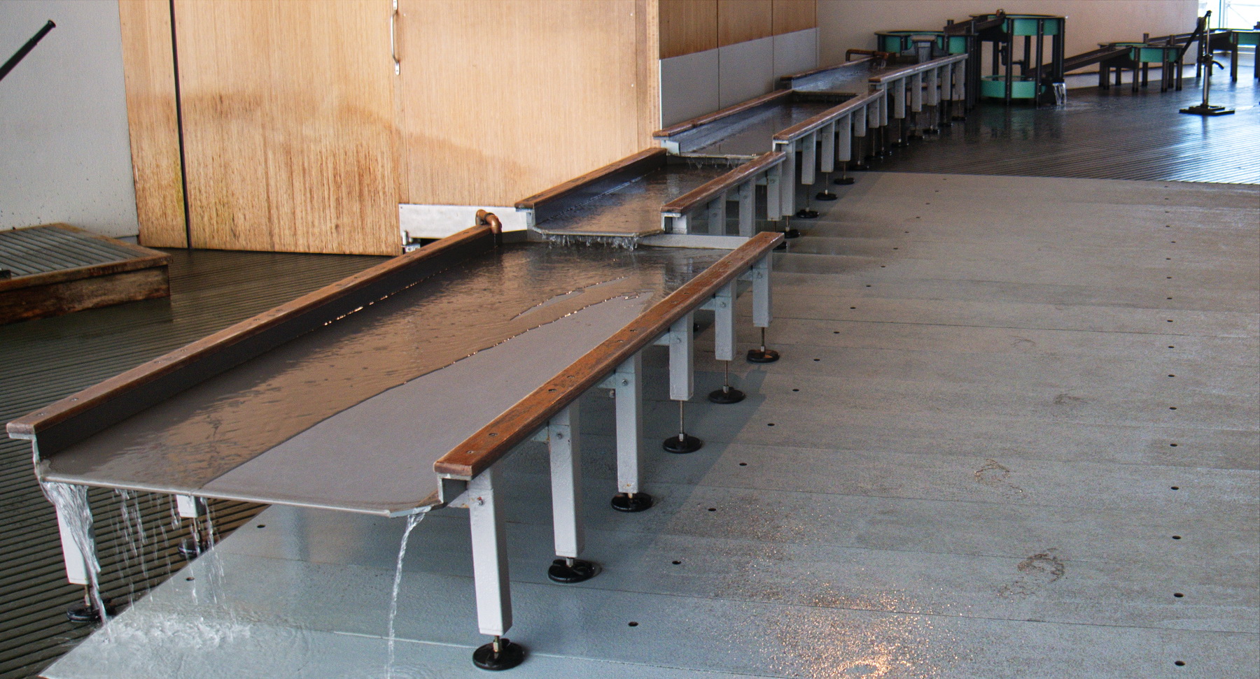
The cascading water tables of the Children’s Museum provide an open-ended tactile experience in which children touch and feel water, experiment with flow, and build structures using heavy blocks. These blocks are the primary affordance by which children can create an effect which isn’t simply momentary. They can be used to make channels, dams, and pools which slowly fill.
The Waterfall Fireworks project aims to expand this experience by introducing additional blocks which can extract energy from the flowing water and create lighting effects which respond to the flow rate. These self-contained blocks include a freely rotating waterwheel. Once a block is placed within a dam or channel that guides water flow to rotate the wheel, LEDs within the body of the block flash strobe lighting patterns out into the water. The patterns provide a visually engaging counterpoint to the water surface reflections and highlight the dynamic visual rhythms of the water coming off the wheel.
The visitor experience might begin by finding one of the wheel blocks among the other non-buoyant blocks on the table. Either the wheel shape will suggest placement within a water flow, or a child might simply use it like any of the other blocks to build a structure. If the structure creates a consistent flow, the wheel will turn and the block will store energy until it can begin to strobe out light. Once a visitor discovers the new visual potential, the person may rearrange the structure to take advantage of the effect. With a longer engagement, a visitor may discover how different flow rates creates different lighting strobe rhythms and continue to adjust the placement until the most desirable effect is achieved.
The primary metrics for success are the duration of engagement and the variety of structures explored. An older child might treat this as a game or science experiment and attempt to optimize a dam structure to achieve the most elaborate effect. A younger child might simply delight in causing a visible effect, even if the child simply manipulates the block by hand to cause it to flash.
5.9.1.1. Technical Overview
The most difficult technical component is building a waterwheel generator which produces sufficient power to create a viable effect. Other challenges include engineering an energy storage system, using micro-power intermittent computing, and building a self-contained waterproof housing.
Our chosen approach keeps all electronics inside a waterproof housing by magnetically coupling the rotating wheel to induction coils within the body. The wheel itself will be fabricated from laser-cut acrylic, with press-fit dowel pins used as plain bearings. Small neodymium magnets will be glued to the outer wheel perimeter. A primary reference is the ‘shake flashlight’ in which a sliding magnet can move back and forth inside a coil to generate small current pulses which accumulate as charge in a capacitor. In our prototype, the magnets will rotate past a coil within the housing.
The housing will also be laser-cut acrylic, with tightly press-fit joints glued with acrylic bonder and sealed with silicone caulk. One face will be removable for maintenance, sealed with an O-ring and clamped with screws outside the waterproof volume.
The coil will be fabricated from many turns of magnet wire and glued against the upper face of the housing. The energy storage system will use small switching diodes to rectify the small current pulses and accumulate charge on a supercapacitor.
The computing element will be a Arduino Pro Mini with onboard LEDs removed, operating in an micro-power mode running the Low-Power Library. It is expected that it will stop operating immediately after the wheel stops turning as the voltage drops, then begin operation again after a few seconds of turning as the charge accumulates and the capacitor voltage rises above the minimum operating voltage. The Arduino will directly drive eight narrow-beam (high brightness) LEDs arranged along the walls of the box.
Early proof-of-concept tests will use external power to evaluate the form and lighting effects in parallel with development of the power system. If the power accumulation system fails to perform adequately, the backup plan is to include a small battery for use during the first site demo. This will limit the run time but allow testing the play patterns and engagement.
Other issues: adding ballast to keep the box denser than water; deriving a rate of speed measurement from the generator output.
Feasibility Calculation
Assuming:
- water flow over wheel is 15 cm wide, 0.5 cm deep, moving at 10 cm/sec
- water descends 1 cm in contact with wheel
- generator efficiency is 10%
- peak current consumption = single LED + Arduino = 25 mA
- peak power consumption = 25 mA * 3.3V = 83 mW
The power calculation:
- The total water mass rate is 15*0.5*10 = 75 cm^3/sec = 75 grams/sec.
- The total mechanical flow power = 0.075 kg/sec * 0.01 m * 9.81 kg m/sec^2 = 7 mW.
- Net generated power = 7 mW * 10% = 0.7 mW.
- Maximum electronics duty cycle = 0.7 / 83 mW = 1%
So the effect with a 1% duty cycle will be sparse; either it will take some time to accumulate energy and emit a burst of activity, or each individual strobe flash will be fairly muted but more frequent.
5.9.1.2. Milestone Objectives
Proof-of-Concept. The principle objective of the proof-of-concept phase is verifying that the essential play pattern is feasible by building a waterproof enclosure with a passive waterwheel and externally powered strobe LEDs. This will test the following technical objectives:
- waterwheel construction and pivoting
- enclosure waterproofing
- amount of illumination necessary to be visible in water
- test minimum strobe duration and LED energy use
Generator Technical Test. In parallel with the core development will be the evaluation of generator magnet and coil configuration and the charging circuit. The first step will be to purchase and disassemble a shake flashlight to measure typical power output and reverse-engineer the charging circuit. In parallel with this
Low-Power Computation Test. In parallel with the core development will be the evaluation of micro-power Arduino technique. This will involve modifying an Arduino for lower baseload consumption and testing the open-source low-power operation libraries.
Phase 1 On-Site Test. The first on-site test will feature a single self-contained unit to be deployed on the water table, with internal LEDs and a freely rotating waterwheel.
There are several contingent outcomes envisioned:
- If the generator effort has moved quickly and the low-power computation problems solved, the device will be fully-featured and water-powered.
- If the generator effort is still in progress, or if the generator effort has been successful but the low-power computation work incomplete, then the housing will include a small battery to power the Arduino and LEDs. The wheel will include magnets to trigger a Hall effect sensor to provide a rotation rate measurement.
5.9.1.3. Management Strategy
The two group members will work closely on the overall design drawings to ensure consistency, as well as the flashlight reverse engineering.
Responsibility for subtasks will be allocated as follows:
Person A. Manage materials purchasing; iterate waterproofing of housing; iterate waterwheel design; test waterwheel bearings; test effects of different flow configurations (overshot/undershot/reverse).
Person B. Test LED strobing; design and build prototype LED array; iterate generator coil design; prototype charging circuit; prototype Hall effect sensor circuit; evaluate low-power Arduino operation.
5.9.1.4. Bill of Materials
| Quantity | Part Name | Description |
|---|---|---|
| 1 | front panel | custom laser-cut acrylic enclosure panel |
| 1 | back panel | custom laser-cut acrylic enclosure panel |
| 1 | bottom panel | custom laser-cut acrylic enclosure panel |
| 2 | side panel | custom laser-cut acrylic enclosure panel |
| 2 | wheel hub | custom laser-cut acrylic side panel for water wheel |
| 7 | wheel blade | custom laser-cut acrylic impeller blade for water wheel |
| 1 | O-ring retainer | custom laser-cut acrylic panel for supporting O-ring |
| 2 | LED bar | custom laser-cut acrylic LED mounting bracket |
| 2 | wheel shaft | stainless steel dowel pin for water wheel shaft, size TBD |
| 4 | panel screw | socket-head cap screws for fastening bottom panel, size TBD |
| 1 | O-ring | standard O-ring, size TBD |
| 1 tube | caulk | clear silicone caulk |
| 1 | generator coil | generator stator coil wound from magnet wire |
| 7 | magnets | neodymium disc magnets for wheel generator, size TBD |
| 1 | Arduino | Arduino Pro Mini, modified for micro-power operation |
| 1 | supercap | 1F 5.5V super-capacitor |
| 8 | LED | white high-brightness LED |
| 8 | ballast | 100 ohm ballast resistors |
| 5 | diode | Schottkey switching diodes for charging circuit, exact part TBD |
| 1 | Hall sensor | Hall-effect sensor for independent rotation rate estimation |
5.9.1.5. Budget
| Amount | Category/Description |
|---|---|
| $20 | clear 6mm acrylic stock |
| $15 | Arduino Pro Mini, SparkFun DEV-11114 (for low-power modifications) |
| $10 | high-strength magnets |
| $10 | magnet wire, supercapacitor |
| $10 | shake flashlight for evaluation (Amazon Prime) |
| $5 | silicone caulk |
Estimated Total Costs: $70
The group members have agreed to split excess out-of-pocket costs equally.
5.9.1.6. Timeline
| Week 1 | brainstorm, ideate, form group
draw concept sketches
write this project plan
|
| Week 2 | place order for flashlight, magnets, Arduino Pro Mini, magnet wire, supercapacitor
purchase caulk from Home Depot
select wheel pivot parts and LEDs from lab supplies
draw production designs for enclosure and waterwheel
fabricate first enclosure prototype
test water sealing
fabricate first waterwheel prototype
fabricate first LED bar
test proof-of-concept prototype (milestone)
|
| Week 3 | disassembe and analyze flashlight circuti
fabricate generator coil or borrow from flashlight
prototype generator circuit
glue magnets to wheel
measure generator power (milestone)
modify Arduino Pro Mini for micropower
set up low-power libraries
measure low-power operation currents (milestone)
|
| Week 4 | assemble and wire final LED bars and circuit
finalize magnet and coil placement
finalize generator circuit
program lighting patterns
test full system underwater
on-site testing (milestone)
|
5.9.1.7. Sketches
The following concept sketches represent a rough design for the overall form to illustrate the components, size, and overall appearance. Features not yet detailed in this design include the wheel pivots, panel joinery, o-ring retainer insert, generator coil geometry, LED support bars, bottom panel retaining screws, electronics mounting, and wiring.
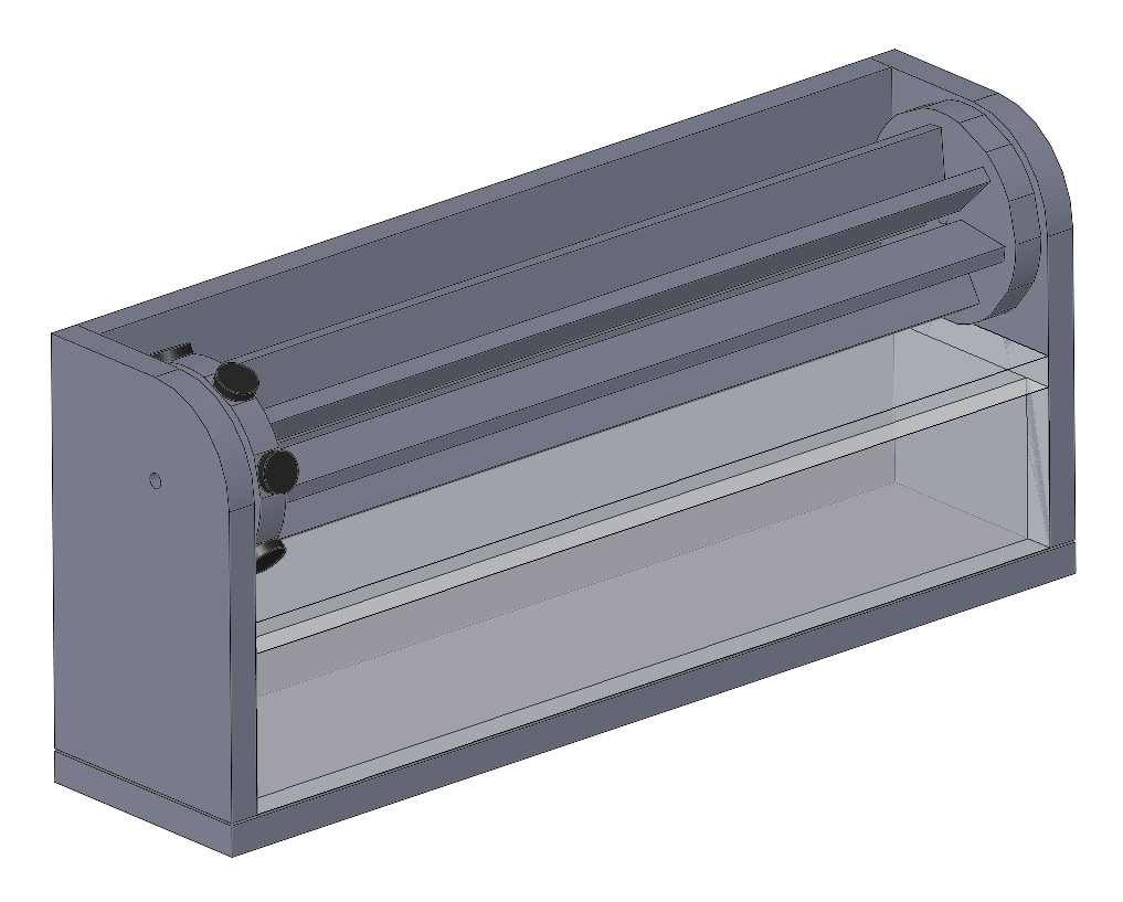
Concept sketch for a Waterwheel Fireworks block. The upper portion includes a freely rotating waterwheel with magnets to induce currents in the generator coils inside the lower waterproof housing. All of the panels are clear acrylic to allow internal strobing LEDs to illuminate the water.
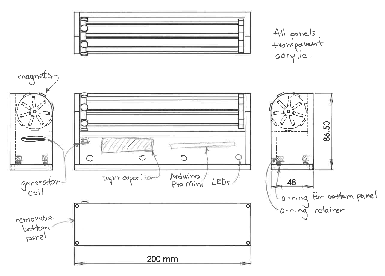
Multiple-view concept sketch for a Waterwheel Fireworks block. The internal electronics are only roughly drawn. The electronics include an generator circuit with supercapacitor energy storage, Arduino in micro-power mode, and an array of LEDs. The bottom panel is removable for maintainance, sealed with an o-ring.