7.4. Tutorial: SolidWorks Basics
These notes are meant to accompany an in-class tutorial presentation, and may not necessarily stand alone. These notes are being preparing using SolidWorks 2017 Education Edition on the new IDeATe PC cluster laptops.
7.4.1. Getting Started
First, run SOLIDWORKS 2017 by double-clicking on the desktop icon. We are currently experience some licensing hiccups with the HSMWorks plugin, so it may take several tries; if asked, you may select ‘disable HSMWorks’, we won’t be using it today. It will take a minute or so to load.
For most operations, there are multiple pathways to begin: toolbars, menus, context menus. Eventually, efficient and fast usage of SolidWorks involves learning the meaning of many icons to pick actions from toolbars and context menus. For now, we’ll try to keep it beginner-friendly with a minimum of shortcuts.
7.4.2. Creating a Part
From the file menu, select New. The default New Document menu should appear:
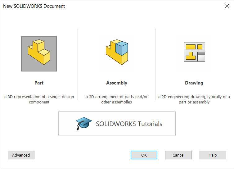
Select Part and confirm with OK.
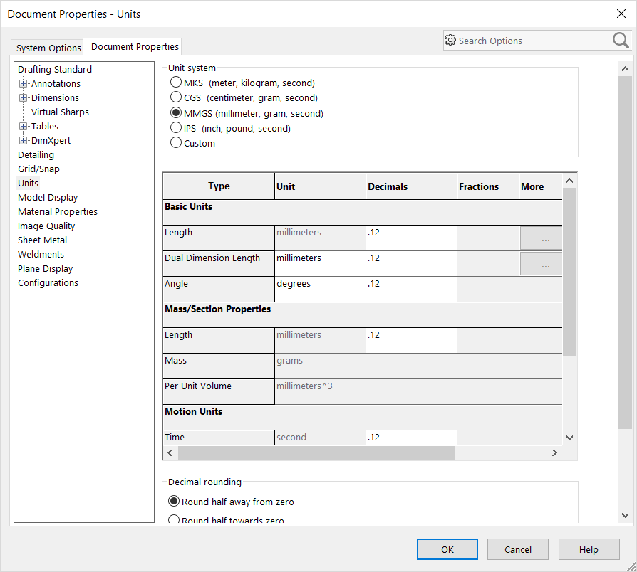
Before we begin, let’s set the units to millimeters. The stock installation uses inches; this is normally personalized to your working practices. Open the Options menu and select the Document Properties tab, the select the Units tab in the left column. Choose MMGS (millimeter, gram, second) and confirm with OK.
We will be creating a laser-cuttable part as an extrusion from a planar sketch. Here is one way to begin a new sketch:
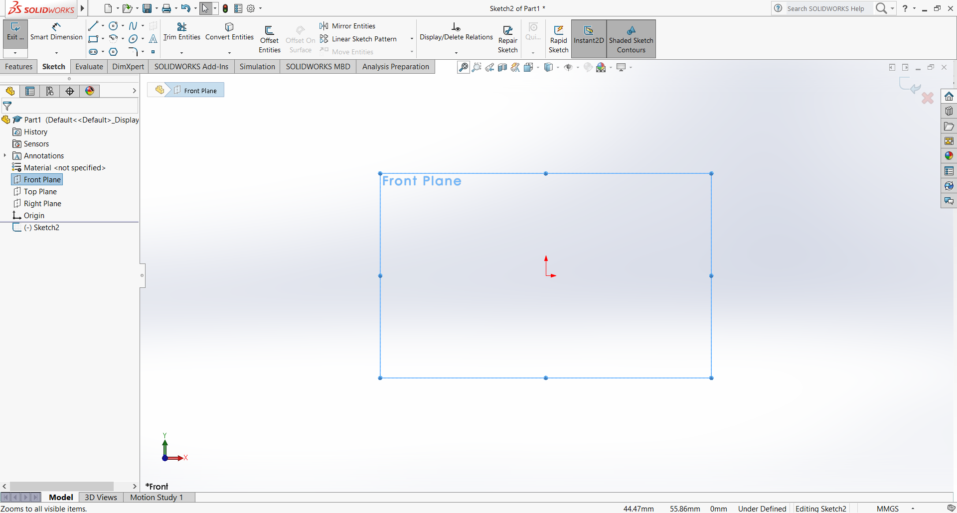
- Select the Front Plane from the FeatureManager Design Tree in the left panel.
- Switch the ribbon control to Sketch.
- Select the Sketch operation from the left side of the ribbon.
The graphics view will pivot the display so the plane is viewed orthogonally, and the display will enter sketch mode:
We’ll start by creating a prismatic rectangular solid. Choose the Corner Rectangle tool from the Sketch ribbon, or find it under Sketch Entities on the Tools menu. Click and drag anywhere in the graphics view to form a rectangle.
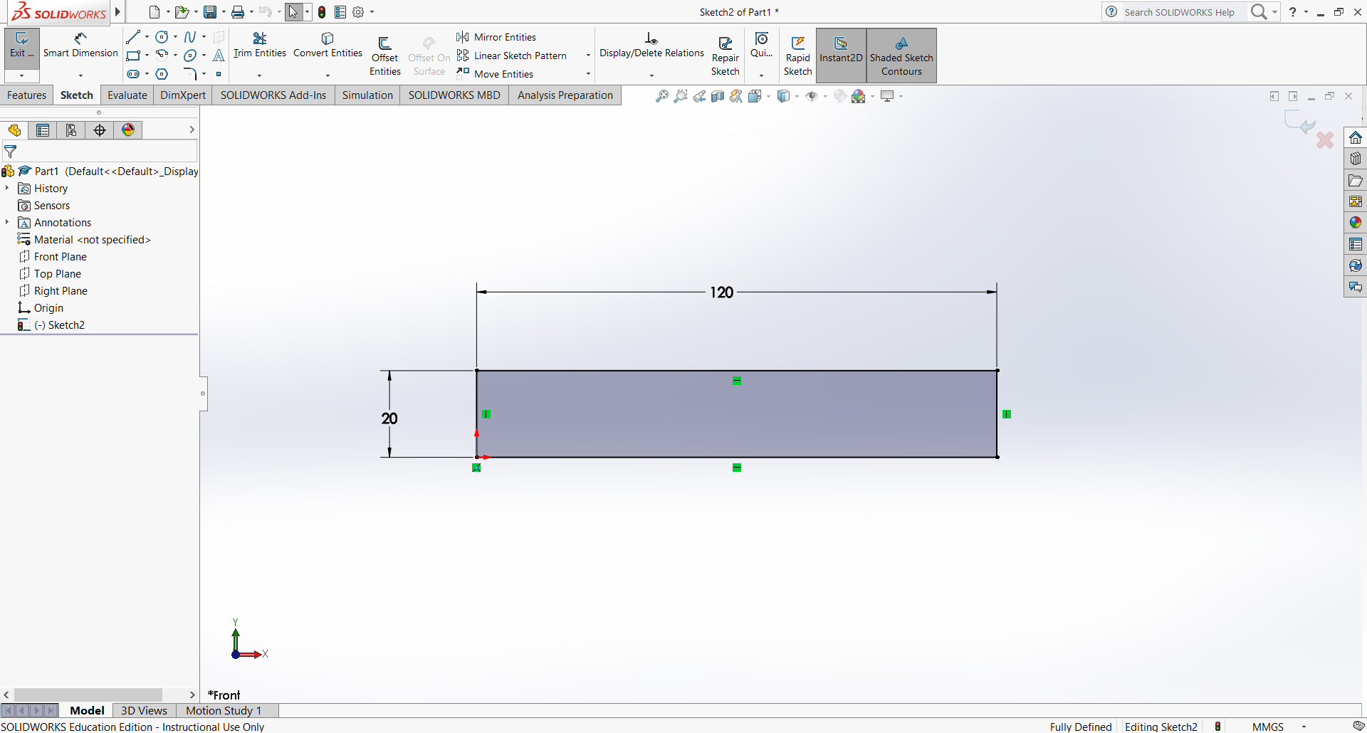
This would be enough to define a solid, but it won’t have a specified size, so we’ll first add one of the most common relations: a dimension. Select Smart Dimension from the ribbon, then select the top edge of the rectangle. Click to place the numeric dimension, then enter 120 in the numeric Modify dialog.
The dimension tool remains active so you can click one of the side edges. Set it to 20 mm. Press the ESC key to leave dimensioning mode.
Note that the edges remain blue: the sketch is still under defined. Try dragging the lines or corners around; the rectangle maintains its shape, but the position on the plane is unspecified. We can add a relation to make one corner coincident with the world origin so the part has well defined coordinates. Select Add Relation from under the Display/Delete Relations tab, then select the left bottom corner, then shift-click to add the world origin point (between the red coordinates arrows) to the selection. On the left, choose Coincident to add the relation. The sketch edges become black; the geometry is now fully defined.
This is such a common operation it is worth showing a faster pathway. Press Ctrl-Z to undo the Add Relation. This time, first select the two points by clicking and then shift-clicking. After the second point, a floating context menu should appear with icons representing different possible relations to add. Click on the icon for Make Coincident to add the relation.
At this point, the sketch should look something like this:.
To create the solid, we will create an Extruded Boss/Base feature. This can be selected from the Features ribbon tab. Enter 6 to set the extrusion thickness. Press enter or click the green checkmark to complete.
To view the solid model, you can use the following mouse buttons in the graphics windows:
- rotate: center button and drag
- zoom: scroll wheel, or shift-center and drag
- pan: ctrl-center and drag
- view menu: press spacebar
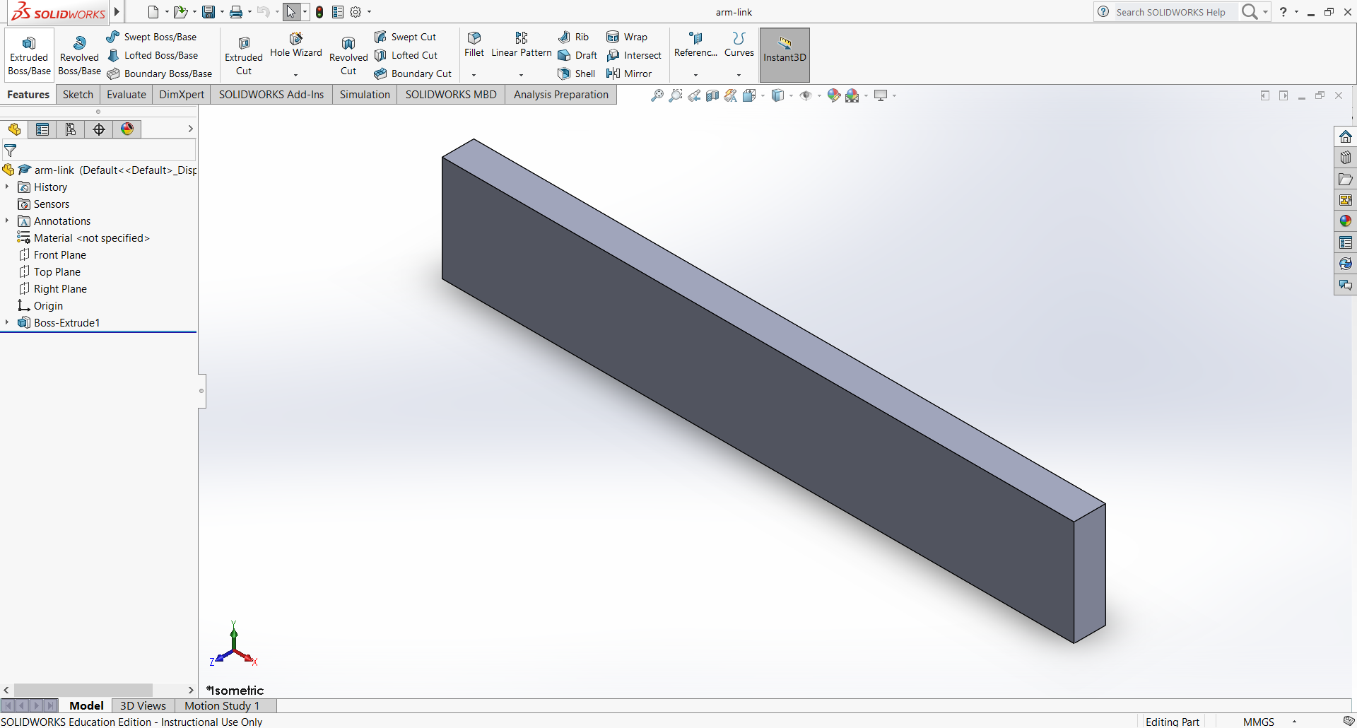
Please save your work before continuing. This will create a .SLDPRT file. It is recommended to choose a unique and meaningful name, as these names can be hard to change once parts are used in assemblies. Here is the solid part in isometric view:
We will now add two pivot holes, one near each end. We will specify the holes using a sketch on a planar surface of the part itself. First, select the front face, then Sketch.
To help locate the holes, we will use a construction line constrained to the centerline. The Centerline item is under the Line item in the ribbon. Draw it roughly down the long axis. We can automatically add the centering relation by dragging one end near the midpoint of a short side. The Midpoint relation icon should appear; release the mouse to allow it to be added. Repeat for the other end.
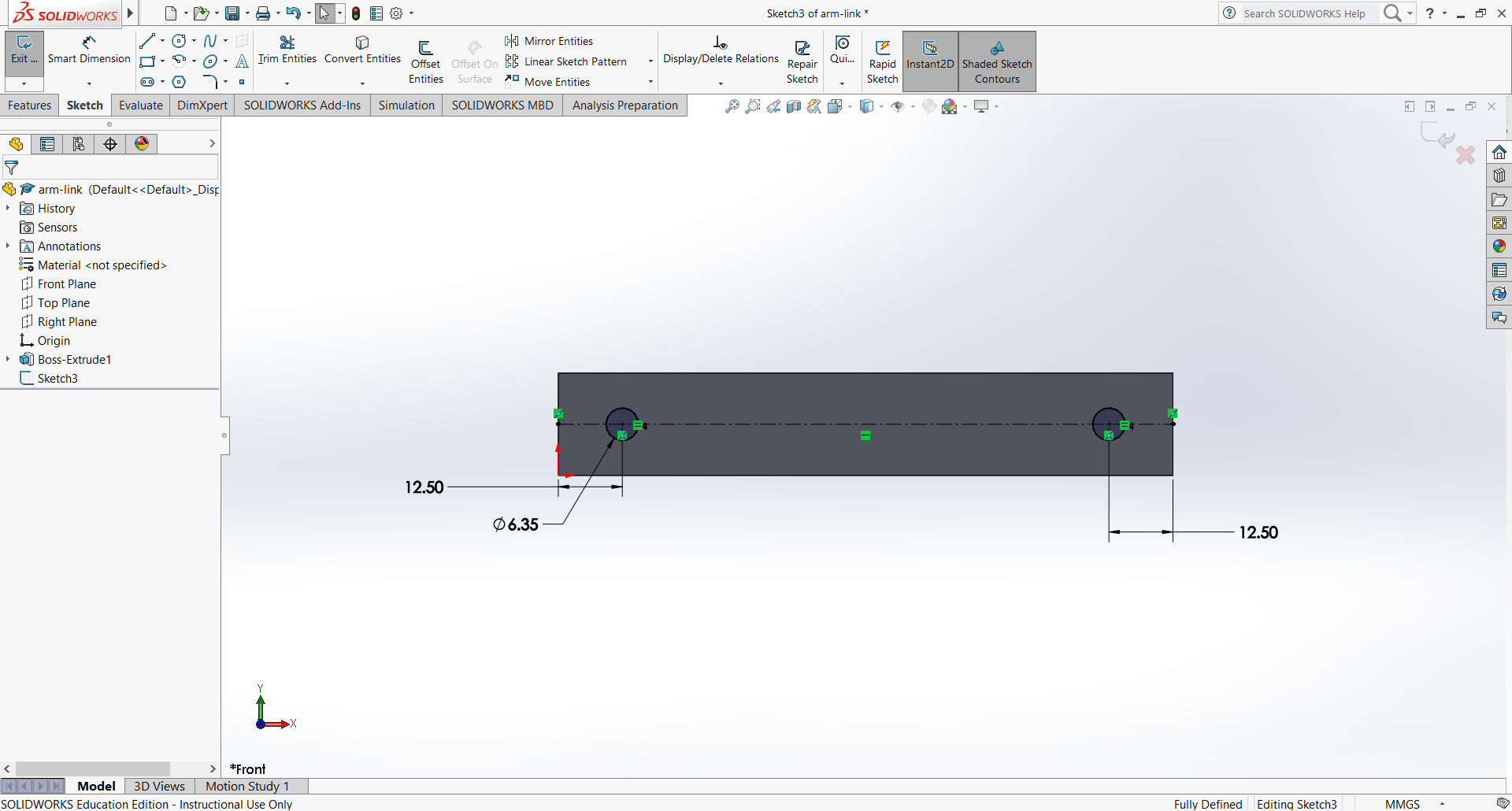
Draw two circles with the center constrained with Coincident to the centerline. Use Smart Dimension to specify a 6.35 mm diameter for one of the holes. The other hole can be constrained to the same diameter with a Make Equal relation.
Now use a numerical dimension to place the center of the left hole 12.5 mm from the left edge, the center of the right hole 12.5 mm from the right edge. (This could also be accomplished by adding a vertical centerline and using a Make Symmetric relation.) Your sketch should look something like this:
To finish the holes, add an Extruded Cut feature. In the Direction 1 tab, select Through All to cut all the way through the part. Save your work.
7.4.3. Creating an Assembly
We will combine your new part with existing parts in an assembly. First, download the following into the same folder as your saved part:
From File/New, create a new assembly.
More TBD.