7.1. Tutorial: Circuit Basics
These notes are meant to accompany an in-class tutorial presentation, and may not necessarily stand alone. For reference, see also Basic Circuits.
Contents
7.1.1. Electricity
- electrons, currents
- potentials, voltage
- metaphorical traps
7.1.3. Digital Multimeters (DMM)
- purpose
- probe locations
- modes: voltage, resistance, current etc.
- later: the oscilloscope
7.1.4. Resistance and Ohm’s Law
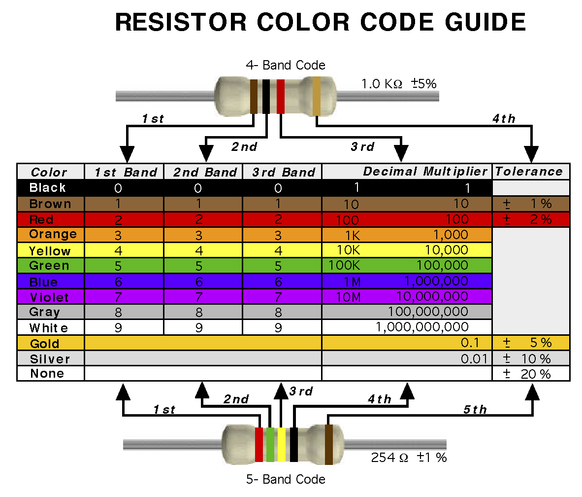
- visual guide


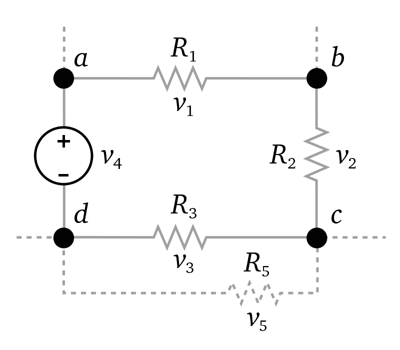
- Each resistor follows Ohm’s Law: \(V = i * R\). This idea can be understood
in several ways:
- a voltage across a resistor will cause a current to flow through it: \(i = V / R\)
- a current through a resistor will induce a voltage drop across it: \(V = i * R\)
- the resistance is defined by the observed ratio of voltage drop to current flow: \(R = V / i\).
- an empirical property
- an engineered property


