Interactive Paper Airplane Wind Tunnel
Philip Baker & Evan Hill
12.6.2017
Abstract:
The goal of the project was to create an interactive experience centered around children creating and testing their own paper airplane designs. Our intent changed through each iteration from a focus on airplane creation to an interaction oriented around controlling the airplane to better suit the younger children. The option of creating and flying a paper airplane remained a part of the interaction though we found moving the airplane in the wind tunnel to be the characteristic that captured the attention of the children. For our final installation, we created a wind tunnel that housed a paper airplane mount that allowed the participant to move the airplane side-to-side and up and down using a joystick control. To help capture the attention of children and to aid in initiating an interaction, the airplane mount was programmed to move with an autopilot mode when not in use.
Objectives:
The central idea for the project was a paper airplane wind tunnel. Creating a wind tunnel with interactive computing features was the main goal of the project. Within the wind tunnel enclosure, we aimed to create a mount for the airplane that could move up and down. The airplane’s motion could be controlled with a joystick. Initially, the joystick also controlled the rotation of the fan. The implementation of a control system was intended to create a simplified flight simulator experience. Our next goal was to create a system for monitoring the stability of flight. We originally intended our project to focus on testing different airplane designs so quantitatively measuring and analyzing the airplane’s flight was essential. The final goal for our project was to include visually appealing elements such as lights or movement to attract museum visitors. We intended for these combination of features to enable an interaction that allows children to create paper airplane design and then to fly and test these designs. Our project was intended to be something which could be explained to children while also creating wonder and excitement.
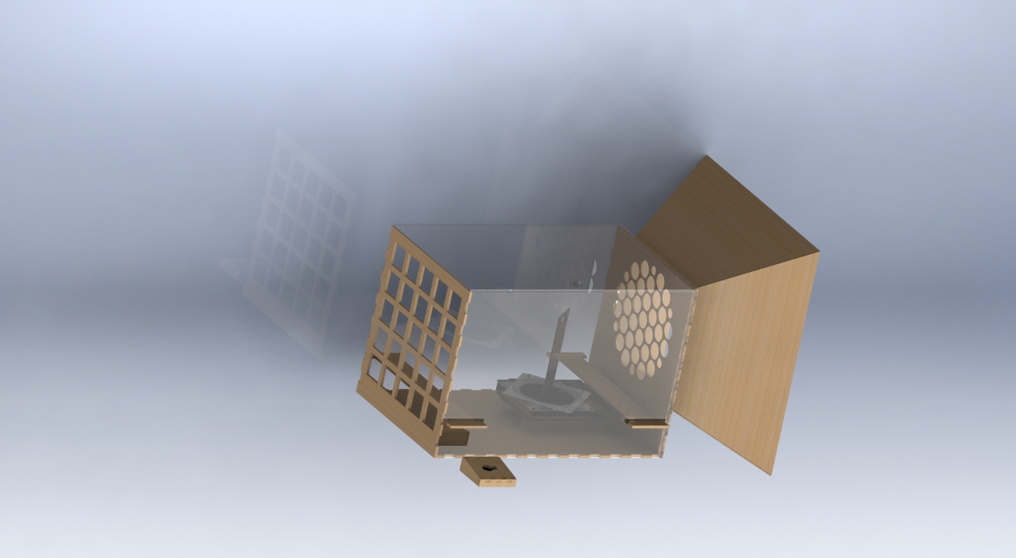
Implementation:
For each aspect of our project we tried to keep the design as simple as possible to reduce the complexity when troubleshooting and modifying the design. The dimensions of the enclosure were chosen in relation to the first fan we used. We built the tunnel body out of a mix of wood and acrylic to ensure stability and enable viewing. The top of the tunnel was hinged to allow for easy access to the airplane mount. The tunnel was modeled in Solidworks to ensure flush connections at the edges of the pieces before they were manufactured. For our first iteration, we designed the wind tunnel to have a rotating fan which was actuated using a servo, a 2:1 gearbox, and a turntable. All of the parts in the fan turntable assembly were created in Solidworks and assembled to check for tolerance issues before laser cutting the physical parts. This helped to ensure a well-constrained gearbox. A 9 inch diameter circular fan was used to create the airstream and a filter using plastic straws was constructed to straighten the flow before entering the tunnel. To simplify the up and down control of the airplane, we designed the airplane mount to be a thin rigid wire mounted to a servo horn. The wire allows the plane to twist and flutter normally while also also for precise positioning. In order to quantify the airplane’s stability we designed a system of servo-mounted rotating arms that are positioned to be slightly higher than the tail end of the airplane. A moving infrared break beam sensor was created by mounting an emitter to one arm and a receiver on the opposing arm. All 3 servos are mounted on a laser cut acrylic stand which was designed for precise motor attachment and alignment.
For our airplane and fan control, we used an Arduino to map the input values from the joystick to a range of degrees that serve as constraints for the servo. Our first control code mapped the joystick input to an angle and moved to that position immediately. This result in very quick and rigid movement. The arms of the IR beam were programmed to move to the same position as the airplane mount servo. We designed the IR arms to be positioned above the tail end of the airplane so that the beam is only broken when the plane is fluttering in the air. Our plan was to count the numbers of beam breaks or ‘flutters’ in a given time period and relate this to the quality of the airplane’s flight. Due to the low resolution of our scanning system (only 1 emitter and 1 receiver) we found it difficult to obtain consistent results for many different airplanes.
Testing showed that rotating the fan produced negligible effects in the flight of the plane so our second iteration of the project switched from a rotating fan to a rotating airplane mount. During our first test at the museum the controlling of the plane captured the children’s attention the most, and this observation drove many of the design modifications for our second iteration. The same gearbox and turntable were used by replacing the fan mount with a base for the airplane mount. New parts were created and imported into the old Solidworks gearbox assembly to check tolerances before manufacturing. Adding rotational control to the airplane mount increased the airplane’s range of motion creating a more dynamic and interesting flight simulation. It also made the interaction more appealing to kids as it makes it easier for them to see the physical effects of their input. We designed and programmed an autopilot mode to move the airplane through a specified pattern when not in use. The autopilot mode was intended to spark children’s curiosity by ensuring our project was always in motion. To aid in the visual appeal of our project, we included LED strips in our second iteration which were programmed to shift through various colors.
We replaced the 9 inch circular fan with a 20 inch box fan in order to increase the airstream power for our second iteration. Once we switched to using a larger box fan we designed a duct by creating an assembly in Solidworks with the tunnel and fan and taking measurements for crucial dimensions. We then used these dimensions to design a duct assembly in Solidworks which would securely funnel air into the wind tunnel.
Outcomes:
We accomplished our original goals for the project, but throughout the process we altered these goals and our intentions for the project. We were successful in creating an interactive wind tunnel that had the capability of quantifying flight stability although the flight stability scanner needed some tuning in order to ensure consistent outputs. If we had continued to work on the flight stability scanner we would have had to either have a broad rubric for stability or more scanning inputs to increase the resolution. Many parts in our system performed well at the first test and were simply made to be more presentable for our second iteration. We found during the first testing day that the majority of the children were younger than we expected and that many parts of our planned interaction were not practical for children this age. The characteristics that proved to be too complex were creating a paper airplane that could fly and understanding the flight stability. The young children were not concerned with the quality of the airplane’s flight. All ages showed the most interest in controlling the airplane so we focused on controls for the second iteration. We also included an autonomous flight pattern and lights to increase the visual appeal. Our Arduino shorted on the morning of the final test, so when we wired up the replacement Arduino we decided not to use the lights to protect against potential shorts. On the final test day children of all ages and some parents enjoyed flying the paper airplane in the wind tunnel. Some of the youngest kids simply enjoyed playing with the joystick and paid little attention to the actual airplane. Slightly older kids often tried to move the airplane as far as possible as fast as possible with little to no concern for the quality of the airplane’s flight. Some of the older kids and parents took notice to the quality of flight and tried to control the airplane in a way that maintained steady flight. Every participant seemed to enjoy the experience. The duration of most of our interactions was around 30 seconds so we failed at capturing the children’s attention for an extended period of time. A little over half of the participants attempted to fly the plane by themselves while the others waited to be prompted or asked for permission to do so. While children may have waited to interact for a variety of reasons, one reason may be that the effects of user input in our project were not clearly evident. The autonomous flight pattern and the airplane control created a sense of wonder for many of the children, but our project may have been more successful in holding children’s attention if it had more magical characteristics to it.
Contribution:
While we collaborated on all ideas, the actual responsibility for implementation was often divided between us. Evan, with his background as a mechanical engineer, was responsible for the physical components that were created (gearbox, turntable, tunnel, duct). Phil, with his background as an information systems major, was responsible for all wiring and code created.
Media:
First Demo:
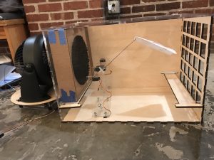
This is our original design that we used at the first demo.
Final Demo: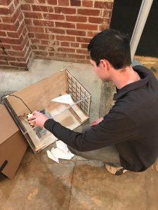
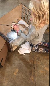
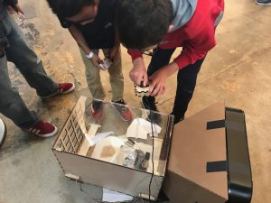
These pictures show users from several age groups demoing our project at The Children’s Museum.
Here is a video displaying the final version of our project in use.
Engineering Drawings
Tunnel Enclosure, Air Duct, and Flow Straightener:
Gearbox and Airplane Mount Assembly
Joystick Enclosure
Source Code
long next_output_time_1 = 0; // timestamp in microseconds for when next to update output 1
long next_output_time_2 = 0; // timestamp in microseconds for when next to update output 2

long flight_interval = 500; // interval in microseconds between output 1 updates
long light_interval = 5; // interval in microseconds between output 2 updates

int output_state_1 = LOW; // current state of output 1
int output_state_2 = LOW; // current state of output 2

#define REDPIN 5
#define BLUEPIN 6
#define GREENPIN 3

#include <Servo.h>

Servo horServo;
Servo vertServo;

int xpin = A0; //yellow
int ypin = A1; //white
int horServoPin = 9;
int vertServoPin = 10;
int xcurr = 90;
int ycurr = 10; // midpoints of acceptable ranges
int xval;
int yval;
int xdeg;
int ydeg;

int xcol;
int ycol;

int r, g, b;
int colorblock;

int mode = 0;
bool xinc = true;
bool yinc = true;

long now;
long last;

void setup() {
  pinMode(xpin, INPUT);
  pinMode(ypin, INPUT);

  pinMode(horServoPin, OUTPUT);
  pinMode(vertServoPin, OUTPUT);

  horServo.attach(horServoPin);
  vertServo.attach(vertServoPin);
  last = micros();
  now = micros();

  colorblock = 0; // for autopilot LED color sequence
  r = 0;
  g = 0;
  b = 0;

  xcol = 0;
  ycol = 0;
}


void loop()
{
  // read the current time in microseconds
  now = micros();

  // Polled task 1 for output 1. Check if the next_output_time_1 timestamp has
  // been reached; if so then update the output 1 state.
  if (now > next_output_time_1) {

    // reset the timer for the next polling point
    next_output_time_1 = now + flight_interval;

    if (now-last > 5000000){
      mode = 0;
    }

    xval = analogRead(xpin);
    yval = analogRead(ypin);

    xdeg = map(xval, 0, 1023, 0, 5);
    ydeg = map(yval, 0, 1023, 0, 5);

    if(xdeg != 2 || ydeg != 2){
      mode = 1;
      last = micros();
    }

    //autopilot flight
    if(mode == 0){
      if (xinc){
        xcurr = xcurr + 1;
      }
      else {
        xcurr = xcurr-1;
      }
      if(yinc){
        ycurr = ycurr + 1;
      }
      else{
        ycurr = ycurr-1;
      }

      // when a limit is reached in the x or y direction, reverse direction of flight
      if (xcurr >= 180){
        xinc = false;
      }
      else if(xcurr <= 20){
        xinc = true;
      }

      if (ycurr >= 70){
        yinc = false;
      }
      else if (ycurr <= 5){
        yinc = true;
      }

      horServo.write(xcurr);
      vertServo.write(ycurr);

    }

    // user is flying the plane
    else if (mode == 1){

      if (xdeg != 2) {
        xcurr = xcurr + (xdeg - 2); // 2 is the midpoint of possible xdeg values
        if (xcurr < 0) xcurr = 0;
        if (xcurr > 190) xcurr = 180;
        horServo.write(xcurr);
      }

      if (ydeg != 2) {
        ycurr =ycurr - (ydeg - 2) ; // // 2 is the midpoint of possible ydeg values
        if (ycurr < 0) ycurr = 0;
        if (ycurr > 60) ycurr = 60;
        vertServo.write(ycurr);
      }

    }
  }

  // Polled task 2 for output 2. Check if the next_output_time_2 timestamp has
  // been reached; if so then update the output 2 state.
  if (now > next_output_time_2) {

    // reset the timer for the next polling point
    next_output_time_2 = now + light_interval;


    // autpilot lighting sequence
    if (mode == 0) {

      switch(colorblock){
      case 0:
        r++;
        analogWrite(REDPIN, r);
        if (r > 256){
          colorblock = 1;
          b = 255;
        }
      case 1:
        b--;
        analogWrite(BLUEPIN, b);
        if (b == 0){
          colorblock = 2;
        }
      case 2:
        g++;
        analogWrite(GREENPIN, b);
        if (g == 256){
          colorblock = 3;
        }
      case 3:
        r--;
        analogWrite(REDPIN, b);
        if (r == 0){
          colorblock = 4;
        }
      case 4:
        b++;
        analogWrite(BLUEPIN, b);
        if (b == 256){
          colorblock = 5;
        }
      case 5:
        g--;
        analogWrite(GREENPIN, b);
        if (g == 0){
          colorblock = 0;
        }
      }
    }


    // user controlled flight lighting
    else if (mode == 1) {
    ycol = map(xcurr, 0, 180, 0, 255);
    analogWrite(BLUEPIN, ycol);
    analogWrite(GREENPIN, ycol);
    analogWrite(GREENPIN, 255);

    }

  }
}
Leave a Reply
You must be logged in to post a comment.