Demo 2: Single-bit Feedback
The second demo introduces one-bit sensing to a mechanical structure. The objective is to build a simple actuated machine which incorporates a single-bit sensor, e.g. a mechanical switch, and uses the input data to affect the actuation output and the mechanical process.
With the addition of sensor input we can create closed-loop systems in which the measurement of the system can be used to control the output. The computation process and the mechanical process are joined via sensing and actuation to form a composite system.
Please keep your goals simple and commensurate with your skills. As before, the primary deliverable is a live in-class demo at the start of class on the due date, along with a brief blog entry.
Learning Objectives
Mount a microswitch and couple it to a mechanical action.
Electrically connect a microswitch to an Arduino using a bias resistor in a voltage divider circuit.
Design several laser-cut 6 mm plywood parts to fit together.
Properly mount a hobby servo.
Create a dynamic physical process combining mechanism, actuation, sensing, and a control algorithm.
Deliverables
In-class demo at the start of class on the due date.
Brief blog entry including:
A brief video clip of the mechanism in action.
SolidWorks files as an attachment.
A brief paragraph outlining the chosen operating principles.
Arduino code.
Prompts
The essence of the assignment is to create an autonomous process in which the mechanism or environment somehow activates the switch. In general, the switch is not intended to be operated by a person; it should sense mechanical state rather than human intention.
A lot of good ideas are essentially clocks: the mechanism is an oscillator with a resonant period, the switch detects the phase, the actuator pumps the oscillator.
More is possible:
the switch could detect an end condition, e.g. like a float valve in a toilet
the switch could count transitions, e.g. of moving parts or objects
the switch could be used to regulate a system to the transition between two states, e.g. like a thermostat
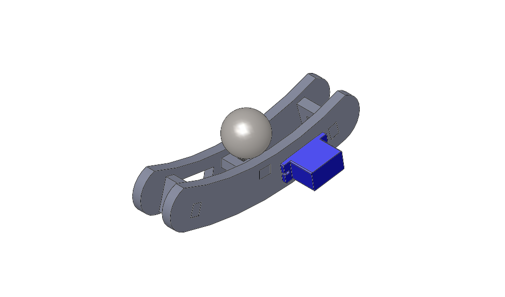
The sample model from the last exercise includes slots for mounting a LTH-1550 photoreflective sensor looking up toward a ball rolling on the upper track.
Criteria
Stick to exactly one input and output.
It’s fine to build off your demo 1 result if you prefer.
A proper actuator mounting will be rigid and removable. For the micro-servos, the best solution uses the two supplied screws to attach the tabs to pilot holes in the support material.
If you use the larger servo, please use the external power supply.
Other rules are the same as before: live demo in class; cite any sources; properly embed video; make links active.
If your Arduino sketch is a single file, please post your code inline, using a SyntaxHighlighter Code block with the Code Language set to “C/C++”, described on the site help page. If it includes multiple files, you may either post them inline or as a zip. Do not post your code as images, as they cannot be cut or searched.