Exercise: Marble Run in Fusion 360
In this exercise we will design a marble run in Fusion 360. A marble run is a structure in which one or more marbles traverse a course primarily powered by gravitational potential. The marbles interact with the track, other marbles, and mechanical gadgets. As a toy or sculptural form, it is a versatile idea, lending itself to handcrafted machines, natural courses, races, objects of contemplation, musical instruments, clocks, etc.
The main objective of this exercise is developing your parametric design skills in 3D CAD for multi-part assemblies. So while the design objective falls within the scope of projects possible for this course, this is intended as a design-only outcome.
The scope and size of the design idea should be chosen in keeping with your existing CAD skills. If you are a novice to parametric CAD, then please keep your priorities centered on creating the design of a sloped track for a rolling ball. If you have prior CAD experience, please choose a scope that includes actuated elements and sensors. For example, this could include gates driven by hobby servos and photoreflective ball sensors (e.g using the LTH-1550 found in the course kit).
References and Inspirations
Jelle’s Marble Runs. YouTube channel with a wide variety of types of marble runs.
woodgears.ca Marble Machines. Many machines, several articles, many photos.
Wintergatan - Marble Machine (music instrument using 2000 marbles) (YouTube)
other related YouTube searches
Objectives
The overall objective of this exercise to design a system of parts which can be parametrically adjusted. The overall design should implement a simple marble run. The work will take place in two phases.
The goals of this exercise are that you should be able to:
Create 2D CAD sketches using parametric constraints to capture design intent.
Design a multi-part assembly using in-context 3D modeling.
Design assemblies using associative dimensions and constraints that support design modification.
Design a rigid structure using orthogonal plates (e.g. boxes and beams).
Export flat parts to DXF files for laser-cutting.
Reference Guides
Please review the following reference guides as needed:
Assigned video lecture clips, including specific commentary on this exercise.
Getting started with Fusion 360 (product documentation).
IDeATe Laser Cutter Guide (course site notes).
Autodesk Fusion 360 (course site notes).
Preparation
The first rule of CAD: always make a paper drawing first.
The second rule of CAD: always make one more paper drawing before approaching the software.
An observant student will note that strictly following this rule will never lead to a CAD design, but the central idea remains sound. Iteratively drawing by hand remains the most efficient way of developing the core logic of a design idea. It is a generative process that raises essential questions and clarifies your design intent. It takes some discipline to avoid leaving contradictions and impossible requirements, but this can be accomplished in a much shorter timeframe than using CAD.
Drawing in CAD is time-consuming. With care, a problem can be modeled well-enough that necessary refinements and adjustments are quick. But in general, a poor understanding of the problem leads to a poorly structured model which cannot be easily and logically iterated.
Well-done, a design process in CAD will raise and answer all needed questions, resulting in a design which can be fabricated, assembled, tested, and solves the problems. At minimum, the process results in a concrete design, but it still takes human understanding to make sure that result is also compatible with physical reality.
Creative Opportunities and Constraints
The simplest ball track is a slot in a horizontal plane of material. However, the only means of sloping it is to make it continually widen, leading to very small slopes and short runs. However, by placing drop holes and extra ‘wedge’ parts in tracks below them to create horizontal velocity, this can be a viable approach. (E.g. see Hape).
Two parallel vertical plates can form a ball track between the edges. The slope can be controlled with a lot of freedom, but the overall path is limited to a single vertical plane.
Following the pinball model, a flat plane positioned slightly tilted with respect to horizontal can provide a reasonable downslope but will need dowel pins and laser-cut barriers to form a pathway. It will also need a sloped support structure to produce the right angle. For reference, fast modern pinball machines may be as much as seven degrees off horizontal; older pinball machines are more typically around three degrees slope.
The ball can be hand-placed to start it, no need for an actuated lift.
Material and Tool Constraints
Every practical design needs to consider the tools and materials at the outset. The abstracted idea may be amenable to implementation using different fabrication methods, but the specific design invariably makes deep assumptions about the means.
For this assignment, please assume you would fabricate all parts from laser-cut 6 mm plywood. This is a versatile material which we use a lot for physical prototyping. If you are not familiar with laser-cutting, please see the IDeATe Laser Cutter Guide. Here are specific assumptions:
The laser cuts along any 2D path, all the way through a flat piece of material. All parts can be drawn as a planar sketch extruded 6 mm thick.
The laser cuts with a kerf approximately 0.2 mm wide. There is no offset compensation, the beam travels straight down the middle of edge geometry, so all holes are approximately 0.2 mm overside, all outside diameters approximately 0.2 mm undersize.
My suggestion is to draw all parts using the desired final dimensions, but with features which are tolerant to cutting variation. This is generally a good practice which accommodates both normal material and fabrication tolerance.
If you have a hole which is a press-fit for a precision part like a ball-bearing, draw it undersize. The parts will overlap slightly in CAD, but once cut, the as-built dimensions will achieve the desired fit. E.g. for a ball-bearing with a 5/8 inch OD, the nominal exact hole would be 15.875 mm, so drawing it as 15.5 mm should result in an as-built hole about 15.7 mm, which is acceptable for a steel-into-plywood press-fit. (N.B. This would be too tight for steel-into-steel, but plywood is forgiving.)
My recommendation for making tabs which fit into slots:
Draw rectangular slots 6.2 mm wide. These will cut approximately 6.4 mm wide to accommodate variation in material thickness. My own habit is to draw the length as an integer, e.g. 15 mm long.
Draw the tabs as a trapezoidal shape to wedge into the slot. E.g., I draw my tabs for 15 mm slots as a trapezoid which is 6 mm high, with each edge sloped 2 degrees off the perpendicular (total of 4 degrees included angle), and the tip dimensioned 15.2 mm. The tip will cut at approximately 15.0 mm wide and freely fit into the slot, but the wider root of the tab will be a a press-fit. Adjacent to the tab (coming off the root) should be at least a few millimeters of edge which will make face contact around the slot to set a definite insertion depth.
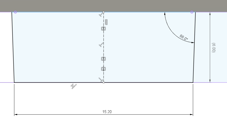
Trapezoidal profile for a laser-cut tab to fit into a laser-cut 15.0 x 6.2 mm slot, both in 6 mm plywood.
Include a tab centerline to use for locating the tab. I recommend center-to-center dimensioning for both tabs and slots to keep the details of the tolerancing out of the design logic.
Laser-cut edges are not perfectly vertical, there is a subtle slope whose exact shape and angle depend on the focal length and calibration of the lens. A well-designed part has a shape and fit which tolerates slightly non-square edges.
The laser can cut sharp inside corners (unlike milling tools). For our purposes, this is generally fine, but sharp corners are stress concentrations which can induce fracture under high loading. This does become a concern when creating press-fits using brittle acrylic parts.
Part 1: Sketches and First Parameterized Part
For the first deliverable phase, I’d like you to create design sketches and draw one main part in Fusion 360. That part will need to include several parameterized features and robustly scale as parameters are varied.
This work assumes you have already set up Fusion 360 and become acquainted with the basic techniques for creating a design, creating a sketch, and extruding a solid.
The following checklist may help you through the design process.
Choose a basic design strategy and ball pathway. If you’re unsure, I’d suggest using a a tilted flat playfield like a pinball game as a starting strategy.
Choose your marble size: this will help determine scale. The kit includes 5/8 inch glass marbles and 3/8 inch steel balls. Standard pinballs are 27 mm diameter.
First draw sketches on paper. Some prompt questions this can answer:
Where does the ball go? Is the path physically plausible?
What parts are needed:
to constrain the ball?
to create a rigid structure?
to support the structure stably against gravity?
Where does each part connect? What is the means of connection?
What dimensions may need to vary as the design progresses?
Is there a viable assembly sequence for putting the parts together?
Choose a part to be the basis for the first parameterized design. E.g., for the ‘pinball’ approach, this is likely to be the playfield.
Create a new design, making sure the units are in millimeters.
I highly recommend beginning a Fusion 360 design by drawing some top-level sketches (outside any component) to help visualize the overall layout. Depending on the nature of your parts, these sketches may be appropriate for the actual part profiles; this kind of top-level design can conveniently collect all the parameters into just a few drawings. Typical starting points might include sketches on two or three orthogonal planes:
a side profile, e.g the projection of the main part outlines onto a vertical plane, possibly along a center symmetry plane.
a top-down plan view.
For a tilted playfield, I recommend sketching the playfield tilt in a side profile and then creating a reference plane using the sketch. That way, the playfield tilt appears as a dimensioned feature in a sketch, and the tilted plane can be the reference plane for a playfield sketch.
Create a component for the first part and either sketch a new extrusion sketch or use profiles from the top-level sketches to create the basic part extrusion.
Detail the part as needed to create a viable design. E.g., add holes for dowel pins, slots for supporting barrier plates, fillets or cuts to contour the edges. Be sure to use sketch constraints to define the feature location in logical ways that will maintain consistency over parameter variations.
Please choose a logical set of parameters to expose, then give them meaningful names and make them ‘Favorites’ in Change Parameters for easy identification.
Part 1: Deliverables
Please be sure to follow the current advice on Fusion 360 Team Protocols for submitting your model for review.
Please share the project containing your design file with me as garthz@cmu.edu.
Please post a short message to Canvas detailing the following:
team, project, and design file names to review
any additional details about the ‘Favorite’ parameters you intend to be varied
Please post an image of your paper sketches to Canvas.
Part 2: Complete Design
For the second deliverable phase, I’d like you to complete the design by drawing all remaining parts in Fusion 360. The complete design will need to include several parameterized features and robustly scale as parameters are varied. You’ll also need to export one part as a laser-cuttable DXF file.
All parts should be defined in separate Components. I recommend keeping each at the top level of the browser tree instead of using subcomponents.
If your design includes a fastener (e.g. screw), please choose and import a specific part and locate it at a final location. If your design includes multiple copies of the fastener, it isn’t necessary to duplicate it everywhere for this exercise. Instead, be sure to create the pilot holes and make a note of this in your writeup. In general, placing all the screws is very time-consuming; it can be worthwhile for rendering images or for identifying critical assembly or clearance problems, but for this exercise would be excessive.
The DXF export is quickly covered in a lecture video, but in brief: Fusion 360 can export any single sketch as a DXF file. My recommended practice is to create a new sketch on a flat face of the part and project the face itself into the sketch. This sketch will include all final contour geometry as lines. The Save as DXF option is available using the right-click context menu on the sketch in the Browser. Note: please do not use the Export option from the File menu, as that will instead generate a DXF rendering of the part as shown on the screen, which will not result in an accurate file for the laser cutter.
Please be sure to identify any new critical parameters as Favorites in the Change Parameters dialog and note this in your writeup.
Part 2: Deliverables
Please be sure to follow the current advice on Fusion 360 Team Protocols for submitting your model for review.
Please make sure the project containing your design file is shared with me as garthz@cmu.edu.
Please upload two files to Canvas:
A DXF file representing the laser-cutter pattern for a selected part. Please always include your name or Andrew ID as a prefix on the file name for any uploaded file, this makes it much easier for me to keep them sorted out.
a brief text file detailing the following:
team, project, and design file names to review
any new details about the ‘Favorite’ parameters you intend to be varied
a brief description of your intent and outcomes
Challenges
If you would like to explore more, please consider the following optional challenge question:
How would you perform computation mechanically using marbles? The marbles could serve as the power source and data transmission. Information could be stored either by marble location or the position of mechanical elements.
Ideas:
Addenda on Materials
The preferred material for this exercise is 6 mm plywood to develop the discipline of designing using the notional material at hand. But other physically plausible material usage is acceptable if there is a specific design rationale.
We generally prototype in laser-cutter-friendly plywood, cardboard, and acrylic. Normally IDeATe Lending stocks the following materials: https://resources.ideate.cmu.edu/quartermaster/sales/pricing
E.g. for short playfield walls, 3 mm plywood or acrylic would be strong enough at modest heights, but if extended too far would be flexible and prone to breaking. That said, this is a design exercise, so thin metal walls are also physically plausible, we just wouldn’t normally have a readily available means of fabricating them.