Exercise: LED with current limiter
Objective
Light an LED safely using a current-limiting ballast resistor circuit.
An LED is a Light Emitting Diode, a type of semiconductor component which emits light directly from a current. The light results from energized electrons moving between quantum states, and so the light emitted has narrow spectral bands with color depending upon the specific chemical composition. White LEDs are actually a composite structure of multiple LEDs of different colors. White LED light is still narrow-band, unlike the wide-spectrum black-body white light emitted from incandescent bulbs.
A diode is a two-terminal semiconductor device which only conducts current in one direction. For this reason, LEDs are polarized, and will not light up if connected backward (reverse-biased).
However, diodes are not resistors: as the voltage across them increases, they will be dark until the voltage is higher than the forward voltage, then the current and brightness will increase sharply as the voltage continues to climb. However, this poses a problem, since an LED connected directly to a power source with a voltage higher than the forward voltage will enter a very low-resistance state, conduct a lot of current, and often burn out or melt.
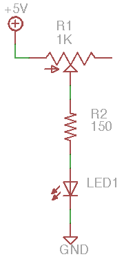
We will frequently solve this by using a ballast resistor in series with the LED. This forms a voltage divider which acts as a very simple current regulator. In the test circuit shown, R1 and R2 act together in series as the ballast. In most applications, a single ballast resistor is adequate; the variable resistor is included here only for demonstration purposes.
A typical red LED has a forward voltage of 1.6V and a full-on operating current of 20 mA. The calculation for choosing the right ballast resistor follows this reasoning:
the current flow through the resistor and LED should be 20 mA for full brightness
the voltage drop across the resistor should bring the LED applied voltage to approximately the forward voltage
assuming a 5V supply voltage, a 3.4V drop across resistor brings the LED voltage to 1.6V
for the resistor, \(R = V / i\), so R can be approximately 170 ohms (i.e. 3.4V / 0.020A).
Steps and observations
Before applying power, measure the variable resistor and adjust it to the upper end of its resistance range.
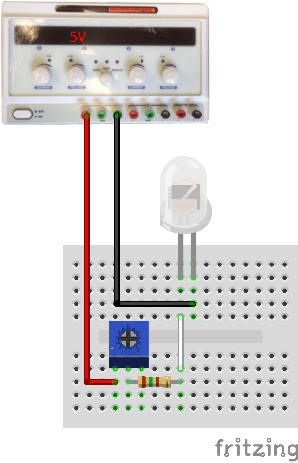
Set up the circuit on a breadboard; a suggested layout is shown below.
Apply 5V and observe the LED light output. Reverse the polarity of the LED to see both forward and backward states.
Measure the LED current while full-on.
Slowly adjust the variable resistor (a potentiometer) until the LED current is 20mA.
Measure the resistor value.
Measure the LED voltage drop, resistor voltage drop, and supply voltage.
Don’t reduce the potentiometer setting further or it may be damaged. Later you will deliberately destroy an LED to see the outcome.
Comments
The potentiometer can be damaged by excessive current in this circuit when the wiper moves close to the powered end since a lot of current will flow through a small resistor.
Diodes can be modeled as a non-linear resistance which changes with the applied voltage: when reverse-biased, the resistance is very high, and almost no current flows. When forward-biased at small voltages below the forward voltage the resistance is still high and only a small current flows. Above the forward voltage, the resistance rapidly drops and the diode can conduct substantial current. For LEDs, this is also the point at which they start to light up.
Green and blue LEDs usually have a higher forward voltage, sometimes as high as 3.5V. Blue LEDs were invented much more recently than red LEDs, it took many years to find an affordable chemical composition.
The lab also stocks infrared (IR) LEDs which emits invisible light; this is the same type used by many remote controls.
For a challenge, find one of the four-terminal RGB LEDs and set up a circuit to create different colors.
Other Files
Fritzing file:
led-current-limiter.fzzEAGLE file:
led-current-limiter.sch