Exercise: Electrical Theory Practice
Objective
Objective: self-test your knowledge of basic electrical theory.
This exercise is a paper exercise to review basic symbols, notation, and electrical theory. These are essential skills for problem-solving within the course and you will be expected to apply these in practice.
Please print this page and answer all questions as best you can without references. Please treat this as an opportunity to check and review your knowledge. The intent is to help us diagnose your skills; please show all work, and write a note if you have difficulty in some area.
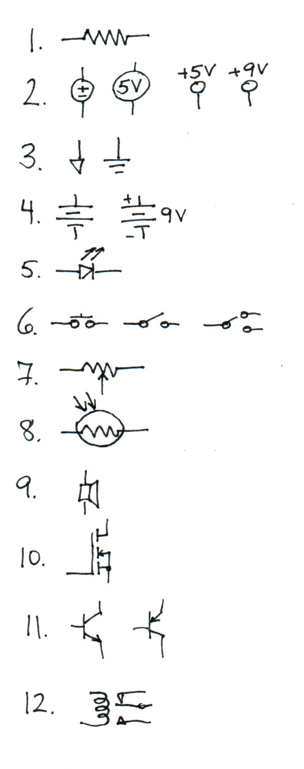
Schematic Symbols
Please write one or more names of the component or concept represented by each schematic symbol below. For some cases several hand-drawn variants are included.
What is the meaning of each of the following acronyms?
Acronym |
Meaning |
|---|---|
SPST |
|
SPDT |
|
LED |
|
DMM |
Please label the anode and cathode on the following.
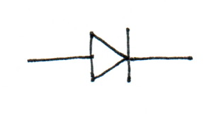
Is the anode or cathode the more positive terminal when the device is conducting?
Notation
What property and measurement units do each of the following symbols typically represent?
Symbol |
Property |
Units |
|---|---|---|
\(i\) |
||
\(V\) |
||
\(R\) |
What do each of these symbols indicate on a schematic?
Symbol |
Meaning |
|---|---|
\(\Omega\) |
|
\(K\) |
Rules and Measurement
In our graph-based circuit terminology, a node is an idealized connection point joining two or more component terminals. The ground is the node which we conventionally designated as the zero volt potential. Potentials or voltages exist between nodes. Currents are measured through a conducting path.
If a voltage \(V\) is measured between two nodes, what is the measurement if the leads are reversed?
What is the canonical form of Ohm’s Law? What are the alternate forms that solve for each dependent variable?
What is a concise mathematical statement that can be made about the sum of currents entering a given node?
What is a concise mathematical statement that can be made about the sum of voltages around a circuit loop?
If voltage \(V_{xy}\) is measured between points X and Y, and voltage \(V_{yz}\) between points Y and Z, what is the voltage \(V_{xz}\) between points X and Z?
Circuits
Please determine the specific quantities requested for each circuit. Please be sure to include correct units.
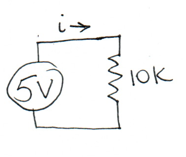
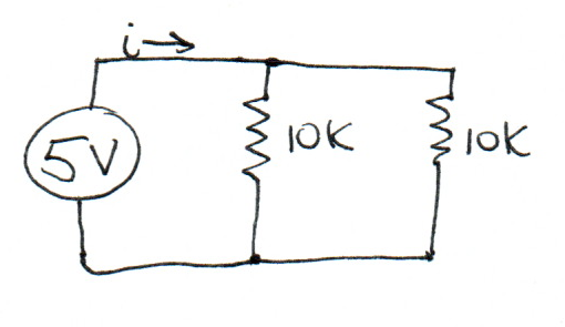
What is the value of \(i\)?
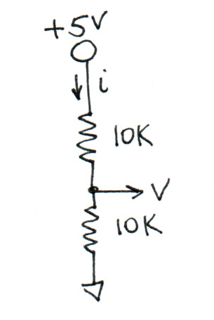
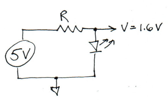
What are the values of \(i\) and \(V\)?
What is the value of \(R\)?
What is the value of \(i\)?
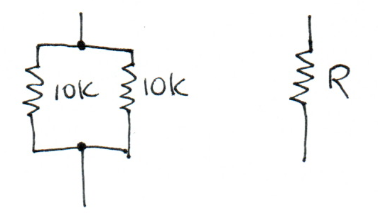
What is the value of \(R\) for which the component on the right is equivalent to the circuit on the left?