Electronic Schematics
Electronic circuits are communicated using schematic diagrams which represent the electrical connectivity using abstract notation. Reading and drawing schematics are essential skills for this course.
Visual Glossary of Schematic Symbols
|
Resistor, annotated as 270 ohms, named R1. |
|
Resistor, annotated as 5600 ohms, denoted as 5.6K, named R1 |
|
Light-emitting diode (LED). Note the arrow-like directionality. |
|
Photocell, or photoresistor. Typically a cadmium-sulfide (CdS) cell. |
|
Single-pole single-throw switch (SPST). The ‘pole’ is the moving part, and it can either connect to the other terminal or leave the connection open. |
|
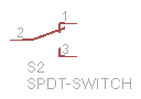
Single-pole double-throw switch (SPDT). The ‘pole’ is the moving part, and it can connect to one of two possible terminals. |
|
Speaker. |
|
DC motor. |
|
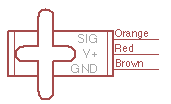
Hobby servo. |
|
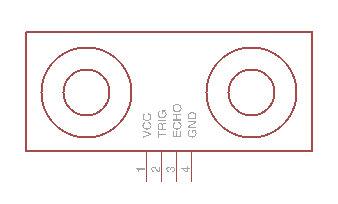
Sonar sensor module. |
|
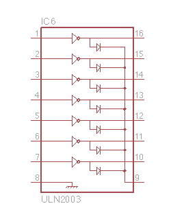
ULN2003 multichannel driver integrated circuit (IC). |
|
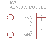
ADXL335 accelerometer module. |


Arduino Uno Schematic
The Arduino Uno we are using is an open design which many companies manufacture. The reference design is available: Arduino Uno circuit diagram.
There are actually two microcontrollers, with one devoted to the USB connection, and the other running user programs and interfacing to the pins. The 3.3V supply is provided by a linear regulator attached to the 5V supply. The power supply automatically switches between USB and external power. The USB supply is fused to try to protect the attached computer from short circuits.