Abstract
Toys and games are becoming progressively more reliant on screens and these screens are the sole source of feedback for the children playing them. Our project objective was to create a game with more tactile and real-world movement that can be used to engage children. We decided to build a tilting marble maze with some form of decision-making and movement within the maze. The physical prototype achieved the objective of a completable tilting maze with real world movement. To enhance the decision-making aspect of the maze a later CAD iteration made the game more complex and generally more exciting to the player.
Objectives
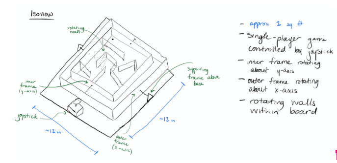
The following were the goals for the marble maze in order of decreasing priority:
- Responsive rotation of a maze via a gimbal system
- Rotation is controlled by a joystick module
- Compact so that it can easily be used by an individual
- Movement within the maze itself (rotating walls)
- Sensory input within the board to control movement
- Concealment of wiring, motors, joystick pins, etc.
Concept and Preliminary Design
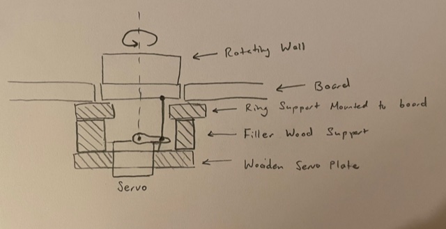
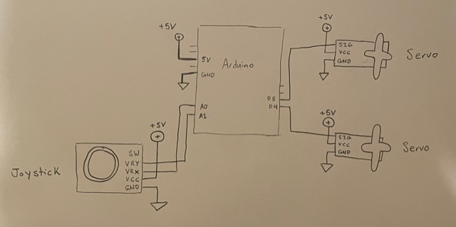
The board would rotate on a gimbal system such that the board could change in pitch and roll. The playing board would be attached to an inner frame and this inner frame would be connected to a servo and linkage that would rotate it about the x-axis. This servo and linkage would be part of an outer frame that rotates about the y-axis by way of a stationary servo and linkage. The maze walls and gimbal frames/stands would be fabricated out of 1/8″ wood so that the entire device would be relatively light. Dowels and bearings would be used to assure smooth rotation about the axis. Additional servo motors would also be mounted beneath the board to rotate certain walls. Rollover switches would be placed on the board with lever switches mounted beneath them to detect whether the rollover switch has been triggered. An Arduino UNO microcontroller would connect the motors and sensors of the board while also receiving user input from a joystick.
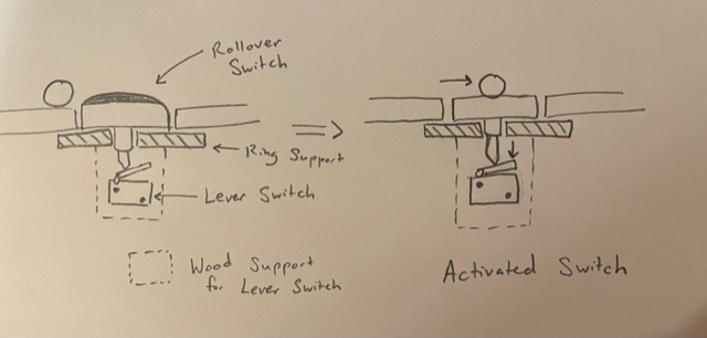
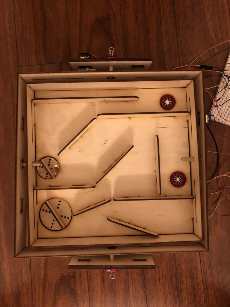
After using prototypes to figure out how to position the gimbal servo motors and linkages, a final physical iteration was made with the main emphasis being the board. Unfortunately, we could not finish mounting of the lever switches beneath the rollover switches so while the maze game is playable, it does not require as much thought from the user.
The below code shows how the gimbal system works by translating input from the joystick into movement of the frames. The code is very raw, with no smoothing filters placed in, just intended to allow user to complete the game without many control frustrations.
#include <Servo.h>
const int outerServoPin = 5;
const int innerServoPin = 4;
const int jsXPin = A0;
const int jsYPin = A1;
Servo outerServo;
Servo innerServo;
int outerRotStart = 90;
int innerRotStart = 90;
int bigWallStart = 0;
int smallWallStart = 0;
int outerRotMin = outerRotStart - 60;
int outerRotMax = outerRotStart + 60;
int innerRotMin = innerRotStart - 60;
int innerRotMax = innerRotStart + 60;
int xPos;
int yPos;
int outerPos;
int innerPos;
void setup() {
//pin setup
pinMode(jsXPin, INPUT);
pinMode(jsYPin, INPUT);
Serial.begin(115200);
outerServo.attach(outerServoPin);
innerServo.attach(innerServoPin);
outerServo.write(outerRotStart);
innerServo.write(innerRotStart);
delay(1000);
}
void loop() {
//read the positions of the joystick
xPos = analogRead(jsXPin);
yPos = analogRead(jsYPin);
//change frame states based on joystick
outerPos = map(xPos, 0, 1023, outerRotMax, outerRotMin);
innerPos = map(yPos, 0, 1023, innerRotMax, innerRotMin);
outerServo.write(outerPos);
innerServo.write(innerPos);
}
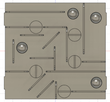
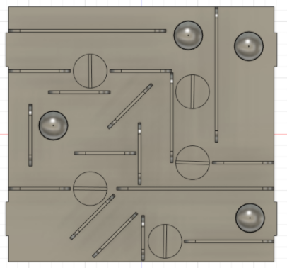
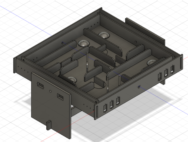
As we were unsatisfied with the level of thought required from the user, further CAD designs emphasized the game element of the marble maze. The design was steered in a puzzle-like direction with multiple switches and rotating walls that the user would have to spend some time thinking through. The new design also has more movement that’s apparent to the player as every rotating wall rotates 90 degrees when any of the rollover switches are triggered. Now that the maze feels like its constantly changing, it can create more excitement for the user while playing it and the extra thought required can create more satisfaction when the user conquers the maze. The board alternates between two states as the user navigates through it as seen below:
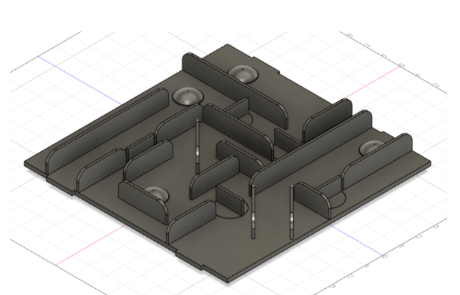
To give the game more challenge and complexity, this new design contains a branching path. The initial physical design just had the user navigating the marble into a certain place before advancing towards the goal. The intention behind complexity is to make the user want to play the game again as each time the game would be slightly different. This idea can be expanded upon in more iterations but the goal of having the maze be compact conflicts with it.
Link to Fusion 360 Project Folder: https://andrew565.autodesk360.com/g/projects/20201106350547781/data/dXJuOmFkc2sud2lwcHJvZDpmcy5mb2xkZXI6Y28uVWhCQlBIakNUWUtQLXAyWkwzQnVTQQ
Continuous Improvement
Moving forward, we could keep iterating and ideating playfields and sensor ideas to create a more arcade-like game. While our current version is more akin to a game that could be found in a homes, we could expand upon our ideas to add different game states and possibly multiplayer modes. Our original idea was to have this be a single-player game as inspired by quarantine. However, if we evolve our idea to become more socially engaging and added more visual aspects via LEDs and sensors, there are many more branches we could explore.
Another idea to increase the replay-ability of the game is to have the user be timed in their completion of the maze. This would encourage players to try again even after winning to try to beat their personal best.
There is also potential for a different goal altogether: learning and education. Due to not reaching the goal of wire/motor concealment, not only is the movement of the maze apparent to the user but HOW it moves is as well. With more guidance from either an outside source (an adult) or indicators within the game itself, a child could learn how modules like servo motors, linkages, and sensors work.
Sources
Inspiration for Gimbal Design from Tilting Maze Final Report – Henry Zhang, Xueting Li
Authors and Contributions:
Shiv Luthra – maze design sketches, Computer Aided Designs, Arduino Code
Amelia Chan – gimbal design sketches, physical manufacturing and assembly
Leave a Reply
You must be logged in to post a comment.