Dillon Shu and Jack Rooney
Abstract:
Waking up in the morning is often difficult. We are always looking for ways to assist us in getting to our jobs on time. Sometimes a loud, blaring sound is not enough to continue us through our endless cycle of work and sleep. That is why we decided to design a lighting system that will help with that. Our Wake-y Up-y Remote-y Lighting ™ makes sure that your lights go on when you silence your alarm because nothing should stop you from completing your labor with a smile.
Our goal was to design something that would turn on your lights when you pick up your phone in the morning and turn them off when you put your phone down before you go to sleep.
Objectives:
Our objectives for the project shifted throughout its duration. While we initially set out to make a working prototype, in the end we decided to make a CAD design that would allow us to circumvent some of the constraints that had limited us when we were trying to make a physical version. Once we shifted to the CAD design, our goal was to make a user-friendly product out of parts mostly available to us. We focused on aspects like design in order to remove any potential barriers for use by a potential user.
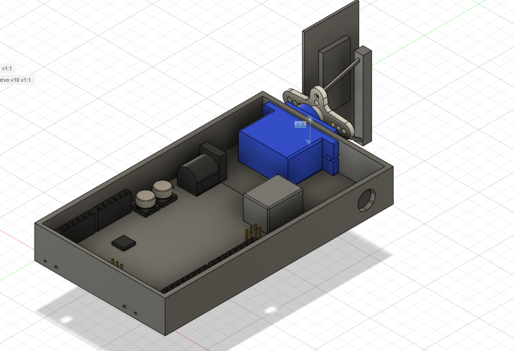
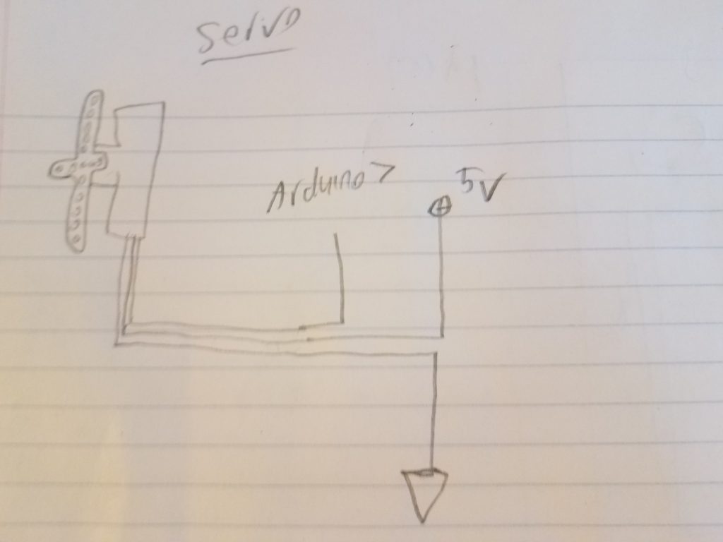
The features we had initially implemented were quite basic in nature. We built both the load cell piece and the light switch mechanism, with the light switch mechanism being a laser cut part attached to a servo that would be pressed down to turn the light on/off. Having ensured that basic level of functionality, we moved onto the load cell but were met with technical difficulties. Though we ended up figuring out what was causing issues with our implementation of the load cell, by that point we had already opted to move to a CAD design.
Implementation:
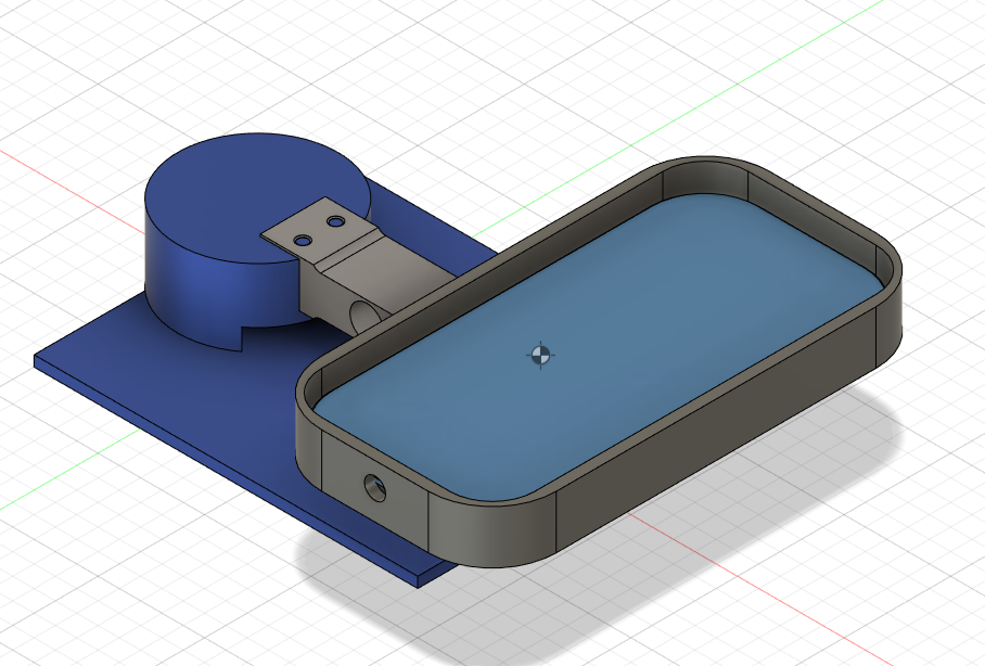
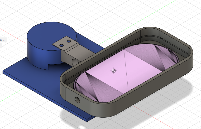
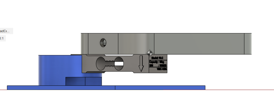
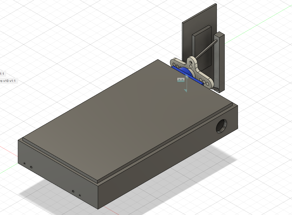
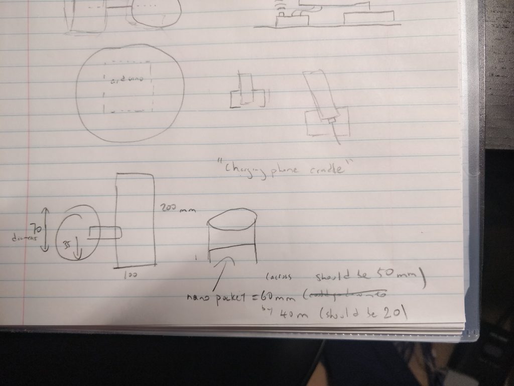
With regards to our final design choices, we hoped to try to remove all reasons for a potential user not to use the product. With that in mind, we tried to make the design sleek so as the user would actually want to leave it on their nightstand. We opted for a phone carriage that was about 50mm larger than our phones in both length and width, primarily because we felt that having a snug fit for the phone would make it more difficult that it need to be to use. We also added the base plate to the nightstand unit at the end to address a problem that we had faced since the outset of the project, which was how to make sure the load cell did not tip over when a phone was placed in the carriage. When initially working with our physical prototypes, we had used our own counterweights to ensure the unit wouldn’t tip over. However, once we switched to a CAD design, we could implement a more efficient design. The base plate crosses over where the center of mass of the entire night stand unit would be, so as to make sure the unit doesn’t tip over. Ideally, if we were to actually create our CAD design in person, we’d like to make sure that both the base plate and the initial counterweight base cylinder were of a heavier material than the rest of the nightstand unit.
Outcomes:
Our biggest success was shifting the focus of the project from physical prototyping to design. Once we decided to work on a CAD design as our final deliverable, it allowed us to think from a brand new perspective not about what we could physically make, but instead what we thought would make the best product. This gave us new takeaways from the project aside from what we learned about the physical parts and gave new insight into what needs to be considered for product design. Our biggest failure was probably the inability to get the physical model working in a timely fashion. Though we did end up figuring out what was wrong with our load cell design, by that point we had already wasted a few days troubleshooting individually and we were both extremely frustrated with the project. More importantly, though, our shortcomings with the physical model led to us deciding to switch to a CAD design so in the end that benefitted us regardless. Because of this, the shape of our final product was more of a product design where we pitched our idea of what we wanted to make to the class.
We also had some basic code written up for our physical prototype wall mount, as seen below.
#include <Servo.h>
const int SERVO_PIN = 7;
const int ON = A0;
const int OFF = A1;
Servo controlledServo;
void setup() {
Serial.begin(115200);
controlledServo.attach(SERVO_PIN);
}
void loop() {
if (!digitalRead(ON))
{
switch_on();
delay(1000);
controlledServo.write(90);
}
if (!digitalRead(OFF))
{
switch_off();
delay(1000);
controlledServo.write(90);
}
}
void switch_on(){
for (int i = 90; i > 0 ; i--){
controlledServo.write(i);
delay(1);
}
delay(1000);
for (int i = 0; i < 90 ; i++){
controlledServo.write(i);
delay(1);
}
}
void switch_off(){
for (int i = 90; i < 180; i++){
controlledServo.write(i);
delay(1);
}
delay(1000);
for (int i = 180; i > 90; i--){
controlledServo.write(i);
delay(1);
}
}
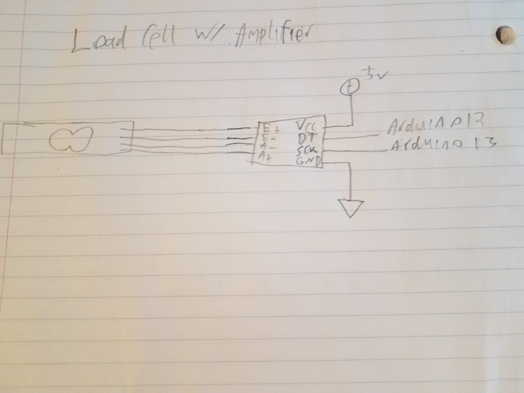
When working on our physical model, we only got so far as to test the functionality of our prototype. We stopped short of combining the load cell’s output and the servo movement. The code above was only to ensure we could get the range of motion we hoped to have in order to turn on the light switch. At the time of writing it, we had planned to factor in load cell output to control the type of motion, but because we had so many issues with the load cell we never ended up doing so. This was one of the major shortcomings in our project. What is not shown are the many libraries for the HX711 load cell amplifier that we had tinkered with in an attempt to get the consistent output we wanted from our prototype, unaware that it was our physical design that was interfering with the output.
Future Work:
Taking this project to the next iteration for us means a few things – a more compact design, a physical model, and expanding the features that we can offer. Even when switching to working on the CAD model we still tried to be mindful as to which resources would have been available for us to use had we wanted to convert it into a physical model. The first step would be to remove the existing load cell in favor of a load cell that looked more like a traditional scale. It would make the design more compact since the large load cell we have used in our design leads to the product being generally unwieldy and oddly shaped. Then, we would have to build a physical prototype of the new model. The whole point of designing the product was to make sure it was usable. Finally, incorporating some of the feedback we had received from our classmates, we believe that adding more features is imperative to helping convince a potential user that the product is the one for them to use.
A few examples of what we’d like to incorporate:
- Potential method of keeping the nightstand unit stuck to the table (perhaps using velcro or magnets) so the user cannot pick up the whole unit
- Some form of lid to prevent removal of the phone once it’s been put in
- This would have to be an optional feature for use. We had toyed with the idea but opted not to use it. One concern for a lid is that at night if someone needs to use their phone as a flashlight they’d have to take it out of the case, and that should be as simple as possible. Conversely, we’d like to try to prevent people from taking their phone out before they’ve fallen asleep/while they’re laying in bed trying to fall asleep.
- Support for further edge cases – Perhaps our biggest takeaway is that we have to consider use cases for the product that are not entirely black and white. We must account for things like having to go to the bathroom at night and not wanting the light to turn on in that instance when you take your phone off the cradle.
- User customizability – with some of the more open ended ways for us to continue expanding the product, the most important thing we can add is a way for users to decide which of these features they’d like to use and which they’d rather disable. Each person has different habits when it comes to falling asleep at night, so the product we create should try to cater towards allowing flexibility. While one person may like the feature of having the lights turn on whenever the phone is removed so as to strictly enforce a “no phone policy”, others may not.
Contributions:
The project was done jointly/collaboratively for the most part. We assembled the physical prototypes on our own as well as the final CAD design (though this can be attributed more to a misunderstanding of the due dates than anything else), but because of the shift in our project most of the work we did jointly in the last two weeks or so was spent on discussion of what to implement within the design. The general trend we followed was that Dillon did more of the design aspect while Jack focused more on the physical assembly and finer details of the design.
Dillon: Sketches, CAD Design for nightstand unit and wall mount unit, design/features input
Jack: Schematics, Soldering + additional assembly of physical prototype, design/features input
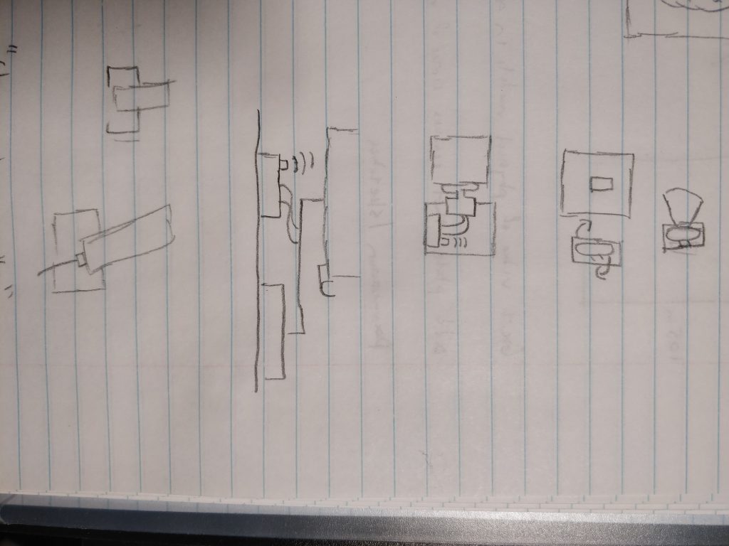
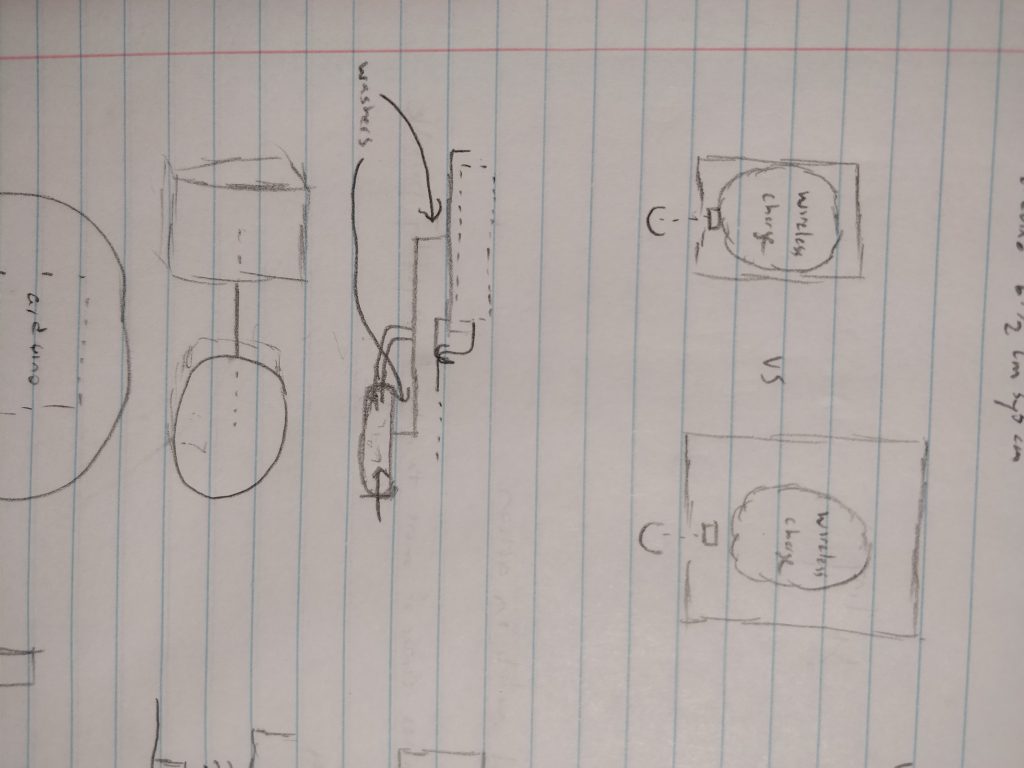
Schematics and Sketches:
Leave a Reply
You must be logged in to post a comment.