Exercise: Multichannel Bipolar Transistor Driver
Objective
Interface multiple actuators using an integrated driver.
An integrated circuit (aka IC or chip) is a multi-component circuit fabricated on a single piece of semiconductor material. The complexity ranges from just a few transistors up to billions of components in a high-end CPU chip.
This exercise uses either a ULN2003 or ULN2803 driver which provides the equivalent of seven or eight individual transistor drive circuits in a single package. Each drive circuit can drive a single device such as a relay, motor, speaker, solenoid, lamp, or large LED. It is polarized, so each channel is either on or off and conducts only one direction. The outputs are open-collector, which in practice means they sink a positive current to a common ground. The inputs are engineered for 5V logic irrespective of the output supply.
Unlike the MOSFET, the bipolar transistors have a noticeable voltage drop and dissipate more power for the same output current. We use these parts because they are inexpensive, robust, and have the convenience of multiple channels.
This particular example uses a low-voltage actuator supply, but the outputs are rated to 50V, so the load can be a DC load at a substantial higher voltage than the logic. Each output is rated for 500 mA maximum current, but in practice the maximum load that can be switched is a function of the overall dissipation. E.g., running too many outputs at too high a current may exceed the total heating limit, which is a function of the package type and heat-sinking.
The outputs include clamp diodes connected to the COM terminal which help absorb voltage spikes typically created when motors or relay coils turn off.
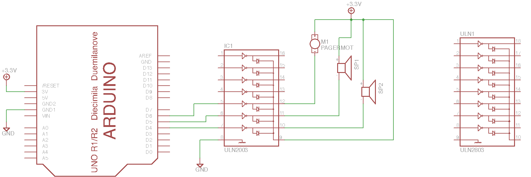
The schematic below includes an optional extra speaker SP2 not used in this particular exercise. The circuit is drawn with a seven-channel ULN2003, but the pinout of the ULN2803 is included for comparison for ease of substitution.
Note the use of the 3.3V supply: an 8-ohm speaker with a half-Watt limit can only handle a 2V RMS signal, which is about what will be achieved given the internal voltage drop of the driver.
Running one speaker or pager motor is about the limit of the Arduino 3.3V supply. For using both speakers or running multiple motors, the use of an external supply is essential. Please exercise caution and good wiring discipline when using external supplies to Arduinos plugged into USB ports; external voltages can damage your computer.
Steps and observations
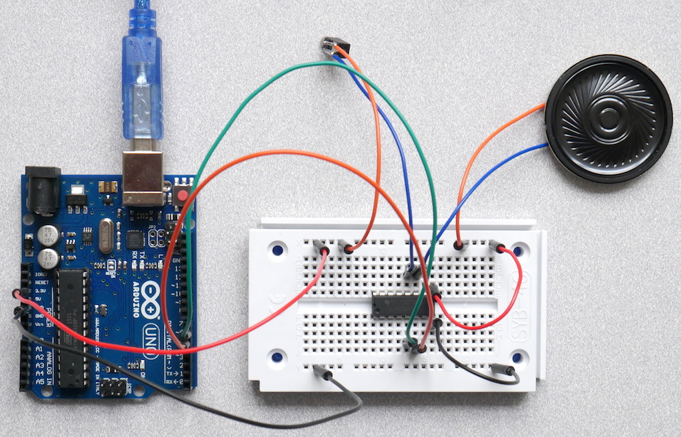
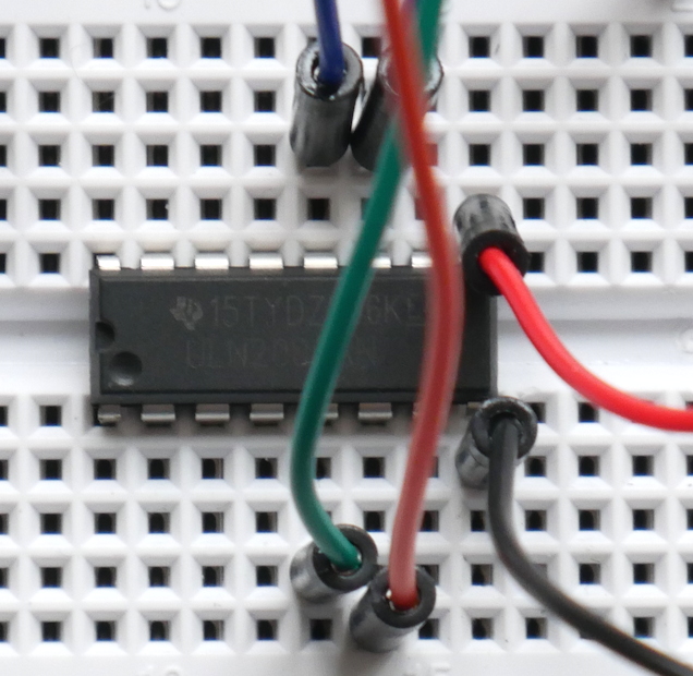
Wire up the circuit on a breadboard. The photos below show a suggested layout and how to orient the chip; the circular dimple denotes pin 1. This is also a good opportunity to look at the data sheet for either the ULN2003 or ULN2803.
Load and run the SoundDemo sketch.
Examine the code for each phase of the output. Can you compose new sequences?
Arduino Code
Documentation: SoundDemo Arduino Sketch
Sketch Folder: SoundDemo
Suggested Layout
The circular dimple denotes pin 1 on the DIP16 package of the ULN2003. Please also note the notch; some DIP packages only include the notch, and some instead mark pin 1 with paint.
Other Files
EAGLE file:
multichannel-driver.sch
Comments
The actual topology of each driver channel is a Darlington pair, a circuit which uses two bipolar transistors cascaded for higher gain. The data sheet includes a schematic approximating the circuit for each channel.
The logic symbol is drawn as a triangle with a circle at the output representing an inverted output which is active-low. In practice, the ‘low’ output is generally sinking power through the load, so it still represents the ‘active’ state, i.e., a high input turns the load on.
Like the MOSFET circuit, note that the input and output circuits are not isolated from each other. Please exercise caution when using external power supplies to avoid damaging the Arduino or computer.