SolidWorks Overview
We have several CAD (computer-aided design) tools available for designing physical structures, namely Rhino and SolidWorks. This overview is intended as a high-level introduction to the essential features of SolidWorks which make it useful for this course. For information on installing SolidWorks, please see SolidWorks Student Installation at CMU.
SolidWorks Concepts
SolidWorks is a parametric design tool. In the broadest sense, this makes it closer to visual programming than drawing: parts are defined by geometric sketch primitives constrained by relations and processed into geometric features through operations. So a cylindrical part might be defined by a circle on a plane that is extruded for a given distance or up to a given point.
Unlike Rhino, that tree of elements is what defines the part and is kept through the life of the part. So if that circle is moved, or split or reshaped, or the extrusion distance changed, the geometry of the solid form can be recomputed.
Using parametric design efficiently involves structuring the part model so that it accurately captures design intent. E.g. if two particular holes are mechanically related, their relative position can be defined by dimensions and relations which capture that mechanical relationship. That way, if other features change and the part shape changes, the holes can maintain their relationship and preserve the intent.
SolidWorks is especially suited for designing assemblies of parts. Machines are typically built from individually manufactured parts assembled together. This is captured in the design model by creating assemblies which define the relative position of individual parts via mates which define geometric constraints. For example, a shaft can be mated to a bearing hole by a concentric mate which limits it to axial rotation and translation (2 remaining freedoms), then further limited by a co-planarity mate between a groove face, snap-ring face, and bearing face which then leaves only axial rotation free. If mates correctly correspond to actual physical constraints, the model helps visualize that all parts have the correct freedoms. And the parametric nature of the constraint tree means that many part dimensions can be changed and other part positions can adapt.
A negative side-effect of the parametric feature tree is that if the structure of the the design intent changes, it can be difficult to modify the tree structure to match. This is because all features are defined in relation to existing features, so if a parent feature is removed, the child feature becomes only partly defined. It takes a great deal of practice to learn to structure models well at the beginning to minimize these problems later.
Essential Ideas and Actions
reference features: planes, faces
sketch entities: lines, circles, construction lines
sketch relations: symmetric, equal, collinear, concentric, tangent, dimension
feature operations: extrude, cut, mirror, radial and linear patterns
assembly mates: coincident, concentric, distance, parallel
number entry boxes: numeric input can include units and calculations
hole wizard
configurations
view mates, isolate, suppress
Good CAD Heuristics
Always sketch your parts on paper first.
If you think it’s time to start modeling, wait and do another paper sketch first. It is so much faster and generative.
If you need a standard component, check online sources for a free model before drawing it from scratch. Be warned, though, that the exact part models may have much more detail than you need. Modeling geometry is as much a process of knowing what to leave out for a particular problem.
Choose a system of units and stick with it. The reality of working in the USA is that metric and inch exist side by side throughout the catalogs and stock. It can be cheaper to buy inch-sized parts and fasteners, but many imported parts are designed in millimeters.
Before you begin modeling, consider the following: natural symmetries in the part, the core form which is most unlikely to change and thus suitable to be a base feature, whether the part may exist in several variations.
It can be hard to appreciate the scale of a CAD feature as the computer monitor can perfectly magnify or shrink details. I recommend keeping rulers and calipers handy for reference to remind you of exactly how much 0.001 inch or 0.1 mm actually looks in the world.
A solid model defined by mathematical primitives is mathematically exact. Of course, any rendering of it as pixels, cutting line segments, or rendered polygons is an approximation, and the precision is ultimately limited by computer numerical representation. But best results are achieved by taking advantage of mathematical constraints such as relations and mates to maintain that exactitude. So for example, it is possible just to visually position parts very closely in an assembly without defining mates and have it look acceptable for a drawing. But these small errors will tend to cause problems later when dimensions are slightly wrong in cut parts, and it defeats the ability of the tool to help find errors such as overlapping parts.
SolidWorks Student Installation at CMU
For current information on student access to SolidWorks, please see the IDeATe CAD Resources and IDeATe CAD Software pages. Following is a brief summary of the process.
Carnegie Mellon has a site license for students to use SolidWorks on their own Windows computers. The installation instructions and license keys are available via https://www.cmu.edu/computing/software/all/solidworks/
The actual installer is available from SOLIDWORKS Community Download at https://www.solidworks.com/sw/education/SDL_form.html
The default installation options will consume about 18 GB of space, but this can be cut at least in half by omitting unneeded packages. The installer presents the default product options after the license key has been entered. By selecting “Change”, individual packages can be added or removed. The following options may be safely turned off for the purposes of this course:
SOLIDWORKS Flow Simulation
SOLIDWORKS Plastics
SOLIDWORKS Composer
SOLIDWORKS Composer Player
SOLIDWORKS Electrical
SOLIDWORKS Visualize
SOLIDWORKS Simulation
SOLIDWORKS CAM
After configuration, the installer will download multiple gigabytes and install the software. The process can easily take 30-60 minutes depending on your network and computer speed.
Exporting DXF Files for Laser Cutting
There are several different methods to export a DXF file from SolidWorks to drive the laser cutter, but I recommend one in particular to guarantee the correct geometry and avoid duplicate lines. As a counterexample, simply using “Save As DXF” with default settings can produce a linework image of the current view, which might laser-cut an isometric drawing of the part but not the precise contours.
The recommended process is as follows:
Open the individual part file. From an assembly, you can always right-click a part and select ‘Open Part’.
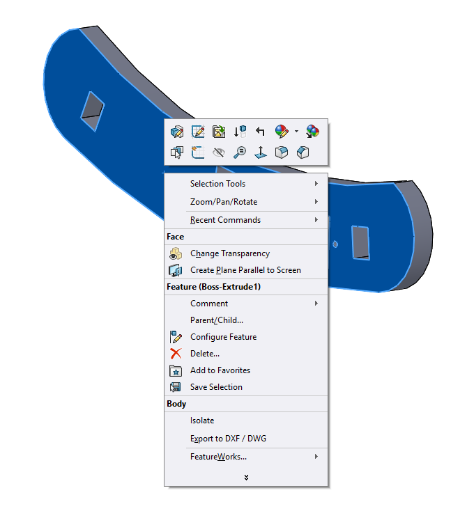
Right-click a planar face representing one side of the stock. The contours of this face will be the cut lines, both inner and outer. On the pop-up menu, select ‘Export to DXF/ DWG’.
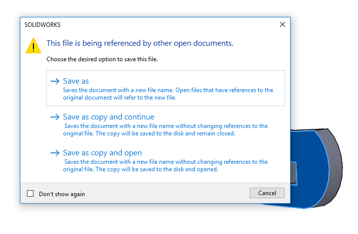
You may get a dialog headlined ‘This file is being referenced by other open documents.’ If so, choose ‘Save as copy and continue.’
SolidWorks then displays Save As dialog in which you may choose an output file path (not shown).
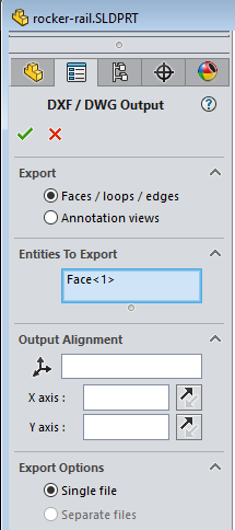
SolidWorks then displays the ‘DXF / DWG Output’ properties panel. The default settings should be correct, but please make sure ‘Faces / loops / edges’ is selected and the ‘Entity to export’ is the previously selected face. Click the green checkmark to continue.
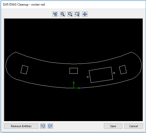
SolidWorks then displays ‘DXF/DWG Cleanup’ popup with a preview of the cut lines. If this looks correct, choose Save.
The SolidWorks DXF/DWG Output PropertyManager Help includes more detail on all the options.
Please note that DXF files do not specify units, so the scale of the DXF file will match the default units of the part file and RDWorks will need to have the correct units manually set prior to import. Using millimeter units is recommended for all parts.