Exercise: Unipolar Drivers
Objective
Control several kinds of high-current actuators from an Arduino using a driver circuit for power amplification.
A microcontroller isn’t very useful without some kind of hardware attached. Most useful hardware requires significantly more power to operate than can be supplied directly from an Arduino output. In essence, the Arduino can signal information using digital or analog outputs, but not deliver much energy. An essential skill is using a driver circuit to control power delivery using that information. Or put another way, amplify the small-energy informational signal to the point where the energy is useful enough to solve an actuation problem.
This exercise will explore a driver circuit which can operate several kinds of actuators. It has the following features:
We will only consider a single-channel driver which operates one device.
The driver circuit is unipolar or single-ended meaning that the current it delivers only flows in one direction. This is primarily relevant to DC motors for which the direction of rotation is controlled by the direction of the current through them; these circuits can stop and start a DC motor but not change its direction. The action of solenoids, relays, and incandescent lamps only depends on the magnitude of the current, not its direction. Large LEDs only conduct in one direction.
We will use an IRF540 MOSFET transistor as the driver. Since the transistor in this exercise is only ever fully ON or fully OFF, we can understand it simply as a form of controlled switch, as explained below.
The circuit uses a digital output. The basic operation is normally binary, either on or off, but pulse-width modulation can vary the average energy delivered by rapidly cycling the signal on and off. For many devices, this produces a linear response, i.e., the DC motor speed varies in proportion to the duty cycle of the PWM signal.
We will also use relays, which are mechanical switches controlled by an solenoid coil. Some relays can switch very high power loads, but note that the relay coil may itself require a driver circuit, resulting in two stages of power amplification: a driver to amplify the Arduino output to drive the coil, and the relay to switch the actuator load.
This circuit can operate devices using higher voltages than are safe for the Arduinos to encounter, so please be careful with wiring discipline. There are alternatives that offer more electrical isolation by using an opto-isolator to connect the Arduino to the MOSFET. Note also that relays provide high isolation between the coil circuit and the contact voltages, limiting the chance of dangerous voltages frying the Arduino.
MOSFET Transistors
A transistor is a type of three-terminal semiconductor component which allows a control current or voltage at the base or gate terminal to affect the current flowing through the device. A MOSFET is a particular type of transistor with very high current gain; the gate input has very high impedance, such that a gate voltage with very little current can control the current flowing between the source and drain. This makes it very convenient for interfacing logic-level signals to loads such as motors.
MOSFETs have a linear range in which the current is proportional to the gate voltage, but this exercise will use it in a saturation mode in which it is either on or off. MOSFETS come in both P-channel and N-channel varieties exhibiting different polarities; this exercise uses an N-channel MOSFET in which a small positive gate voltage relative to the source terminal will cause a positive current to flow from drain to source, activating the motor.
MOSFETs have very low forward voltage, i.e., the voltage drop across the source and drain can be very low, meaning there is very little power dissipated for a given current.
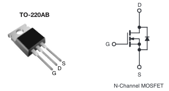
A reference image to the MOSFET package we will use is below. Please note that the gate pin G is actually one of the outside pins, even though the schematic symbol shows it in the center. For this N-Channel MOSFET, the source pin S is usually connected to ground, and the drain pin D to the load.
DC Motors
A DC motor is a starting point for controlling physical motion. By itself, a DC motor spins fast with low torque, so they are usually coupled with a mechanical transmission. If the transmission is an integrated gearbox, it is called gearmotor. This example also works with gearmotors, which are useful for driving practical loads with a minimum of mechanical fabrication.
Unlike an incandescent bulb or relay coil, the DC motor is polarized, and reversing the current will reverse the direction of motion. The circuit in this exercise is unipolar, and can only drive current through the motor in one direction. It is possible, however, to vary the motor speed by turning the transistor drive on and off rapidly to vary the average current through the motor. This is called pulse-width modulation, or PWM.
Relays
A relay is a mechanical switch controlled by an electrical signal. A current through the control coil creates a magnetic field which physically moves an electrical contact from a normally-closed (NC) contact to a normally-open (NO) contact. In most relays, the switch immediately returns to the normally-closed state when the coil is de-energized. Relays come in many shapes, sizes, and configurations; this exercise uses a relatively small relay controlled by a 5V signal.
We can look at it in several ways: as an interface between an informational signal and an energetic signal; as a binary amplifier which allows a modest control signal to control a high-power energetic circuit; as an isolator which allows the input circuit to affect the output circuit without sharing any current.
Some of relays in the lab are low-current and can be driven directly from an Arduino pin; some are mounted on boards which include a transistor driver; some require a transistor driver as indicated.
Relays are relatively slow but very robust. The contacts are just switch contacts, so they have no polarity, and many relays are suitable for safely switching AC line circuits. There are other variants on relays such as latching relays in which one coil is pulsed to change state and another pulsed to change it back. There are relays with many sets of contacts for controlling multiple output circuits from a single control coil.
Relays are the original form of logic component; it is possible to build a programmable computer using nothing but relays. The early automatic telephone switches made extensive use of elaborate electromechanical switches.
Speakers
A speaker is essentially a solenoid coil attached to a paper cone which suspends it in the field of a permanent magnet. The coil generates electromagnetic forces by acting against the magnet field, and the cone couples these forces to the air. Like DC motors, they are bipolar, and a proper speaker amplifier circuit drives the coil currents in both directions. However, pulsing a unipolar current rapidly can still create sound. The example code will need the delay adjusted to make an audible tone; by default it cycles the current on and off too slowly.
Schematic
This schematic shows the general approach for using a MOSFET to drive a unipolar actuator from an Arduino digital output. Be sure to adjust the power supply voltage as needed for the actuator you are testing. Please also be sure to check the Arduino sketch to use the correct output pin, as it varies between examples.
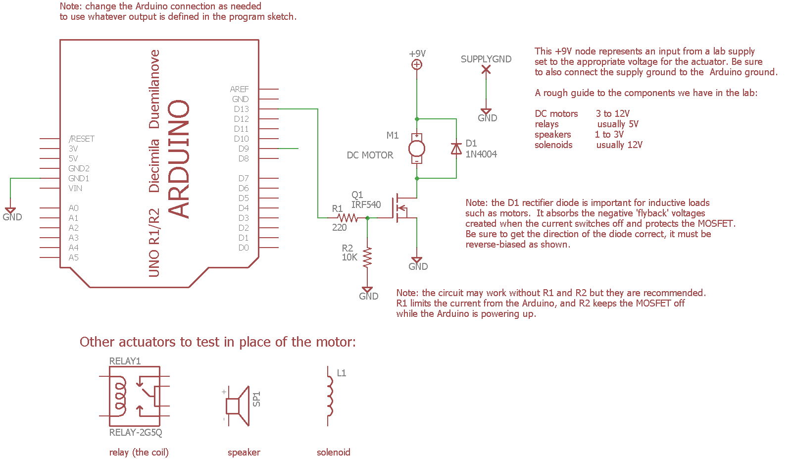
Please note the arbitrary pin assignment on the MOSFET when wiring the circuit; the drain is the center pin and connects to the load in this circuit.
Steps and observations
Testing a DC motor
Find a small DC motor to use as the actuator. You may need to solder solid wire leads onto it first to make it breadboard-compatible. It is then a good idea to test it directly connected to a lab supply to determine a reasonable supply voltage.
Set up the driver circuit on a breadboard as shown, except for the connection from R1 to the Arduino.
Instead, manually connect the free end of R1 to the +5V or GND outputs from the Arduino to confirm that the circuit is wired correctly. The motor should turn on with a +5V input and turn off with a grounded input.
Load the standard Blink example sketch, either from the “01.Basics” section on the Arduino IDE Examples menu or as replicated here on the course site. Look at the code: it is very simple, it just cycles pin 13 high and low.
Connect the driver circuit to pin 13. The motor should cycle on and off. Note that pin 13 is still connected to the onboard LED, so you can also observe its activity.
Add additional
digitalWrite()anddelay()statements to create a different pulse pattern. Explore the limits of timing: how short a pulse will still create movement?Load the Fade example, also from either “01.Basics” or this site.
Fade uses Arduino pin 9 for output, so move the driver circuit input from pin 13 to pin 9. Pin 9 is preferred for this example since it has hardware PWM support.
Run the example. Does the motor speed vary continuously?
Observe the PWM signal on pin 9 using an oscilloscope. Can you find the pulsing? How fast is the cycle?
Testing a Relay
Reload the Blink example and reconnect the driver to pin 13.
Replace the motor with a relay. You’ll want to find a bare relay component, not a relay module which already has a driver circuit. You may need to use a DMM to confirm which pins are the coil (which will have a small non-zero resistance), and you may need to solder on wires if it doesn’t fit into the breadboard.
Run the sketch, listening for the physical motion inside the relay.
Measure the resistance between the relay switch pole and the NC and NO contacts. You should see it cycling between near-zero and near-infinity.
Measure the coil current and resistance, and compute the power dissipated by the coil. You’ll need to temporarily disconnect the relay to put the DMM in series with it, and set the DMM to current mode.
Measure the driver input current. An easy way is to measure the voltage drop across R1 and apply Ohm’s Law: \(I = V_{R1} / R_1\). Note: this may be so close to zero as to be unmeasurable with our equipment, since MOSFETs have very high gate impedance.
Compute the power gain of the amplifier: the output power divided by the input power. Note: if driver input current is zero, this approaches infinity.
Testing a Speaker
Reload the Fade example and reconnect the driver to pin 9.
Turn the supply voltage down to about 2V.
Replace the motor or relay with a speaker.
What do you hear? The overall PWM speed-control pattern varies relatively slowly in this example, but the pulsing of the power itself can be audible as a tone.
Challenges
Relay Self-Switching
Set up a relay circuit in which the coil current passes through the NC contact in series with the coil. What do you expect will happen?
Non-blocking Programming
The Blink example cannot drive two separate patterns on two pins simultaneously,
since it just stalls during delay(). Much of the challenge of programming a
multi-function Arduino program comes down to structuring control flow so the
program never stalls so it can service multiple inputs and outputs
simultaneously.
For a challenge, restructure this program to use millis() to test for the
loop cycles on which to change the output state, then add a second channel of
output with different timing. This will covered in more detail in a later
exercise.
Comments on Bipolar Transistors
You may find reference circuits using the TIP120 Darlington transistor, which is actually two transistors in one package, and we do stock some in the lab. There isn’t much reason to use these anymore; they are slightly cheaper than MOSFETs and more resistant to static dischage, but because they are bipolar junction transistors, they have a much higher intrinsic voltage drop which means they dissipate a substantial amount of heat.
The parts we will use with bipolar transistors are the ULN2003 or ULN2803, as described in Exercise: Multichannel Bipolar Transistor Driver. These combine 7 or 8 channels in one package, and the convenience of this can outweigh the thermal issues.
Arduino Code
Documentation: Blink Arduino Sketch
Sketch Folder: Blink
Documentation: Fade Arduino Sketch
Sketch Folder: Fade
Other Files
EAGLE file:
unipolar-drivers.sch
Comments
MOSFETS
MOSFETS are fast and silent. Modern MOSFETS can handle relatively high power loads with minimal dissipation. The parts are polarized, and driving an output with both positive and negative current (e.g. for directional control) requires multiple parts and steering logic, e.g. an H-Bridge configuration. The polarization also makes them unsuitable for controlling AC circuits. More details can be found on the data sheet for the IRF540 MOSFETs we stock in the lab.
Note that the MOSFET symbol includes a reverse-biased Zener diode which exists as a byproduct of the transistor structure. If the voltage across the MOSFET becomes sufficiently reversed, it will begin to conduct (“avalanche”) and can be destroyed. This circuit has no apparent negative voltages, however, the motor coil is an inductor which can create negative voltage spikes as it turns off. With larger motors in particular, it can be important to place a protective clamp diode around the motor which normally does not conduct but turns on to absorb large reverse voltages.
Arduino PWM
The Arduino PWM run at a very audible 490 Hz frequency. Commercial motor drivers usually run at 20 kHz or higher so the noise is above the range of human hearing.
Even though the PWM signal is a digital waveform using only LOW and HIGH voltage levels, it is still an analog encoding. A PWM signal encodes a single numeric value in the duty cycle, the ratio of ON time to the cycle time, and there is no intrinsic discretization to a pulse width. The Arduino generates the PWM signal using a digital circuit so this particular PWM is quantized as a multiple of the CPU clock period, but it is also possible to generate PWM signals from analog circuits with no intrinsic resolution limit.