Exercise: Motor Marble Run Tile
In this exercise we will design a new marble run component incorporating a DC gearmotor and photoreflective interrupter. The main objective of this exercise is implementing a system blending the passive physics of a marble track, sensor input feedback, and actuated mechanism.
A principal technical objective is gaining design experience with gearmotors. These actuators can provide continuous rotation in either direction at variable speed and are useful for energy input and motion control. Unlike the hobby servos, they do not have any position sensing, so moving them to specific positions will require the use of additional sensing. Photointerrupters are suitable for use as limit switches and coarse encoders to create a degree of position control. The connection between input and output will be made via a computational process on a Pico.
Please choose design goals commensurate with your mechanical design experience and CAD skills. But please consider how to make the device versatile enough to allow different system behaviors to be implemented via software revisions.
For this exercise we will primarily use laser-cut plywood. If you wish to use 3D printing for one or more parts, please consult with the instructor.
Objectives
The overall objective of this exercise is to design and fabricate a small marble run track which incorporates one or two DC gearmotors and one or more reflective photointerrupters. This may be a standalone run or include inputs and outputs so it may be assembled on a sloped table with other active or passive tiles.
The goals of this exercise are that you should be able to:
Conceive and sketch a simple mechanism including ball pathways, sensor placement, moving elements, actuator mounting, and motion transmission.
Create 3D parts from 2D CAD sketches.
that use parametric constraints and dimensions to capture design intent
that support iterative design modification
compatible with the limits of the laser-cutting process
Fabricate, assemble, and test a mechanism combining laser-cut plywood, standard parts, DC gearmotor, photointerrupters, and sensor wiring.
Program a controlled behavior in CircuitPython.
Sample Parts
The sample files for this exercise can be browsed on the course site:
Or as a single zip file:
Sample files are provided on the assumption that students will go farther given a stronger foundation, so these are provided for you to examine and use as starting points. But if you use one as a template, please be mindful that you add meaningful development, not just tweak it trivially.
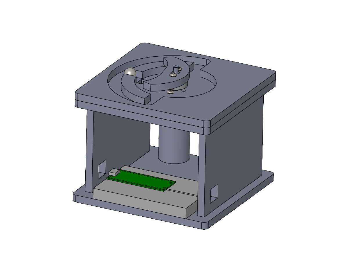
Example of a marble run tile including both a DC gearmotor and a sensor. This design is self-contained without entry or exit ports. A reflective photointerrupter is placed in the playfield where it can detect either a ball or the moving gate.
Material and Tool Constraints
Most of the material and tool constraints are the same as for Exercise: Actuated Marble Run Tile.
Please fabricate all parts from laser-cut 6 mm plywood, unless you get instructor permission to fabricate 3D printed parts.
We will use 3/8 inch steel marbles. A 11 mm track width is recommended for generous clearance.
The Pololu 1997 hub is the most practical way to mount an element on the motor shaft. Please do not glue anything to your motor shafts. The M3 x 10 mm button-head cap screws are a good length for attaching them to 6 mm plywood.
Sample Circuit
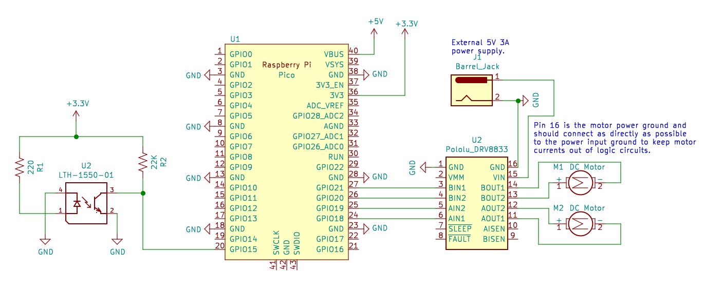
Sample motor driver and sensor circuit. Note that any four GPIO pins may be used to control the DRV8833 dual motor driver. Please be careful with the power wiring, motor voltages can destroy the Pico.
The photointerrupter must be powered from the 3.3V supply on pin 36 to limit the Pico input voltages. Please note that the R2 bias resistor value can be changed to modify the sensitivity; if the moving gate isn’t triggering the sensor, then a higher resistance value will increase the response from a weaker reflection. It is also possible to read the photoreflector using an analog input.
Sample Code
Sample code for driving a DC motor output: DC Motor Examples - Raspberry Pi Pico.
Sample code for reading a digital input: Digital Input/Output Examples - Raspberry Pi Pico.
Deliverables
Live in-class demo of your device.
A short report posted to the course site including:
a zip of your SolidWorks files
a photo and/or brief video
a short text statement reviewing your intent and outcomes
your CircuitPython code posted inline