Exercise: Marble Run Tile
In this exercise we will design a single tile of a marble run in SolidWorks. A marble run is a structure in which one or more marbles traverse a course primarily powered by gravitational potential. The marbles interact with the track, other marbles, and mechanical gadgets. As a toy or sculptural form, it is a versatile idea, lending itself to handcrafted machines, natural courses, races, objects of contemplation, musical instruments, clocks, etc.
The main objective of this exercise is developing your parametric design skills in 3D CAD. The scope and size of the design idea should be chosen in keeping with your existing CAD skills. If you are a novice to parametric CAD, then please keep your priorities centered on creating a single part representing a track. If you have prior CAD experience, please choose a scope that includes multiple parts in an assembly.
References and Inspirations
Jelle’s Marble Runs. YouTube channel with a wide variety of types of marble runs.
woodgears.ca Marble Machines. Many machines, several articles, many photos.
Wintergatan - Marble Machine (music instrument using 2000 marbles) (YouTube)
other related YouTube searches
Objectives
The overall objective of this exercise is to design and fabricate a single ‘tile’ of a marble run which can be assembled on a sloped table with other tiles.
The goals of this exercise are that you should be able to:
Create 3D parts from 2D CAD sketches:
that use parametric constraints and dimensions to capture design intent
that support iterative design modification
compatible with the limits of the laser-cutting process
Export laser-cuttable part files.
Laser-cut parts from 6 mm plywood, assemble, and test.
Experienced students should also:
Create a multi-part assembly including joinery.
Import models for standard lab part components.
Reference Guides
Please review the following reference guides as needed:
IDeATe Laser Cutter Guide (course site notes).
SolidWorks Overview (course site notes).
Preparation
The first rule of CAD: always make a paper drawing first.
The second rule of CAD: always make one more paper drawing before approaching the software.
An observant student will note that strictly following this rule will never lead to a CAD design, but the central idea remains sound. Iteratively drawing by hand remains the most efficient way of developing the core logic of a design idea. It is a generative process that raises essential questions and clarifies your design intent. It takes some discipline to avoid leaving contradictions and impossible requirements, but this can be accomplished in a much shorter timeframe than using CAD.
Drawing in CAD is time-consuming. With care, a problem can be modeled well-enough that necessary refinements and adjustments are quick. But in general, a poor understanding of the problem leads to a poorly structured model which cannot be easily and logically iterated.
Well-done, a design process in CAD will raise and answer all needed questions, resulting in a design which can be fabricated, assembled, tested, and solves the problems. At minimum, the process results in a concrete design, but it still takes human understanding to make sure that result is also compatible with physical reality.
Sample Parts
A suite of sample parts and assemblies can be browsed on the course site:
Or as a single zip file:
Sample files are provided on the assumption that students will go farther given a stronger foundation, so these are provided for you to examine and use as starting points. But if you use one as a template, please be mindful that you add meaningful development, not just tweak it trivially.
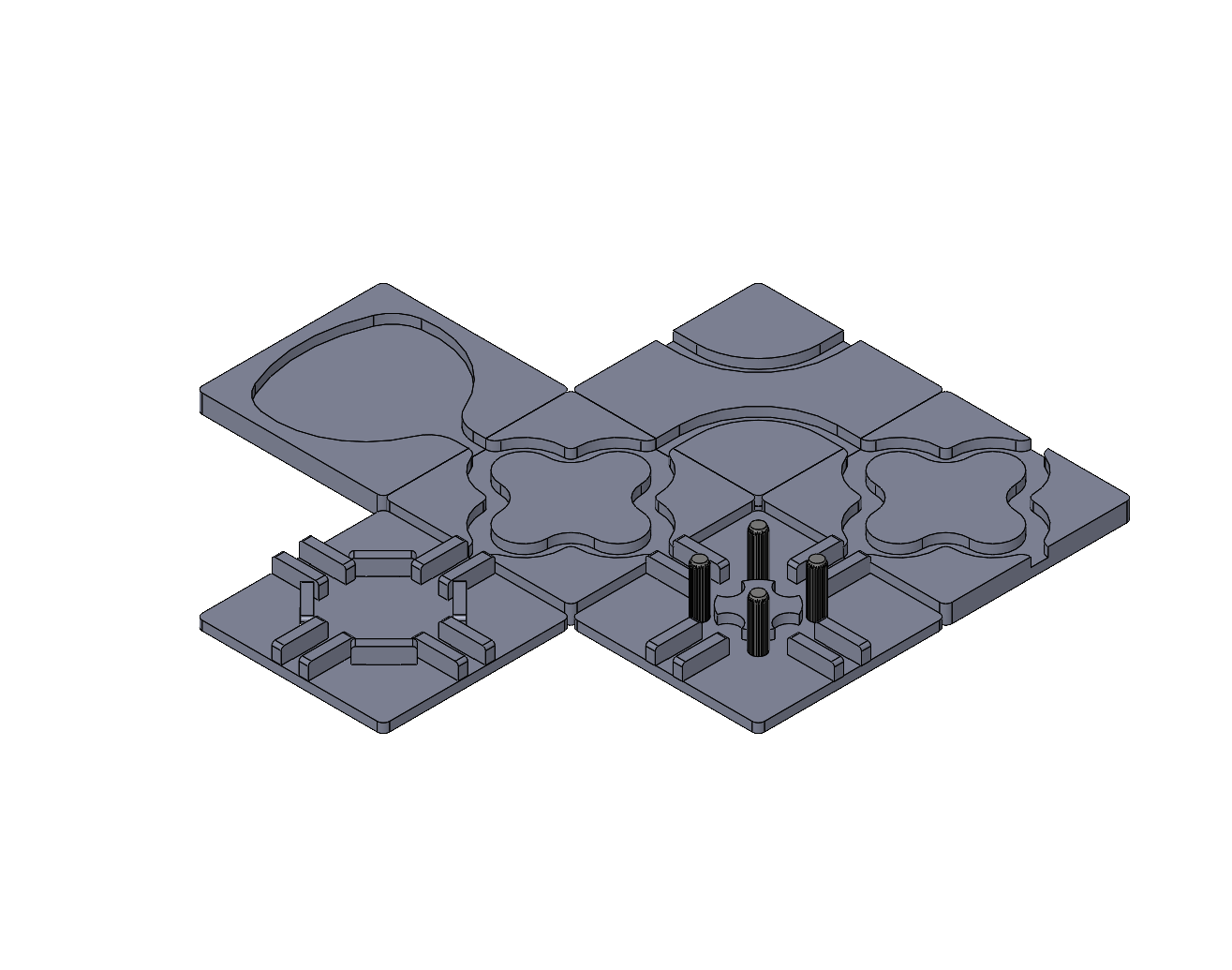
Sample assembly of marble run tiles. This configuration could be tested on a sloped table.
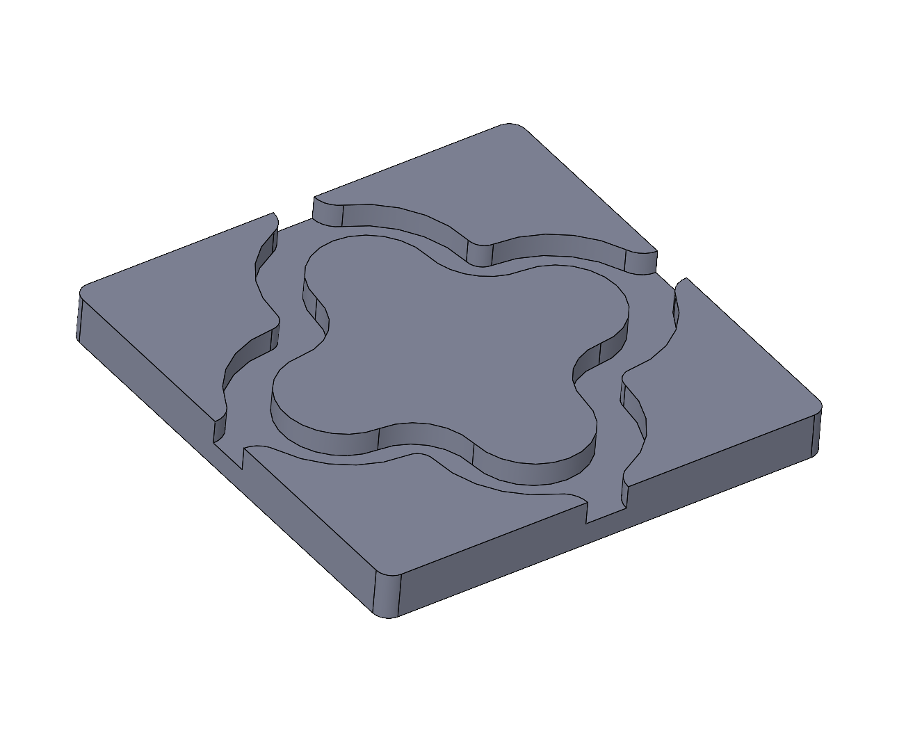
example-1.SLDASM: this tile demonstrates laminating two thicknesses of 6 mm plywood to form channels. This strategy provides the most freedom for the ball path since the laser can cut any shape in the plane.
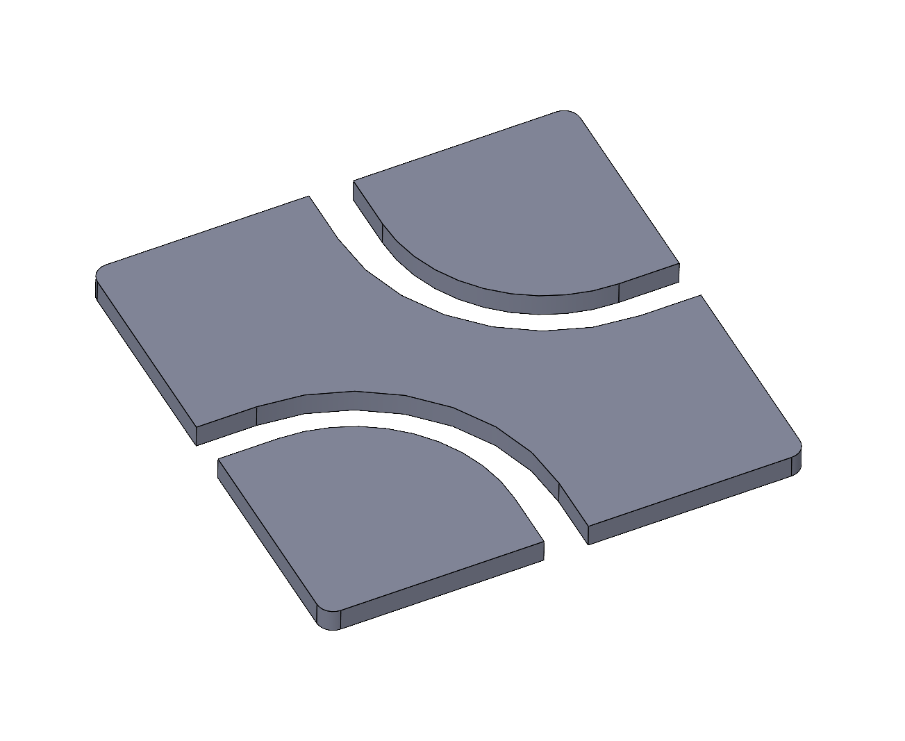
example-1.SLDPRT: the upper lamination layer. This single part has three bodies and will cut as three separate pieces which need to be aligned and glued to the base (not shown).
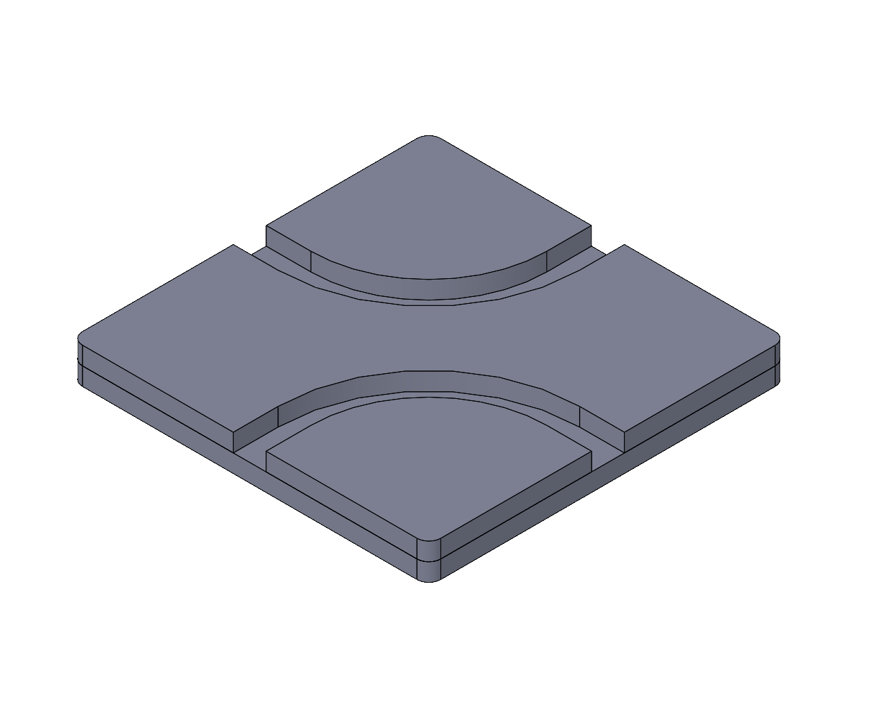
example-2.SLDPRT: a laminated tile drawn as a single solid block. The model doesn’t capture the two layers, it is up to the fabricator to cut separate layers based on the top and bottom face contours.
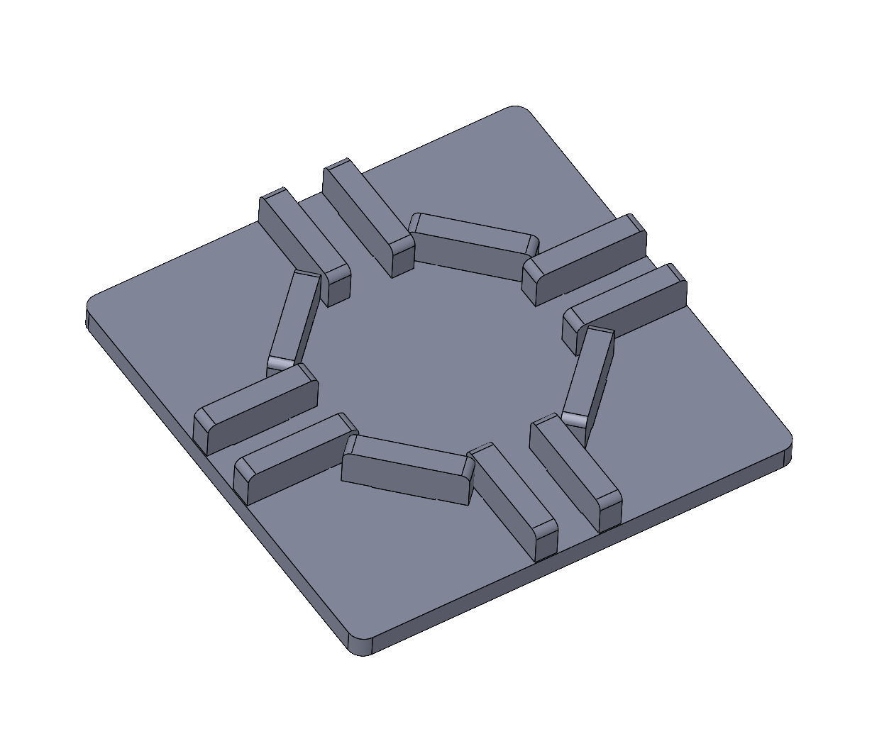
example-4.SLDASM: this tile demonstrates joinery using laser-cut ‘gate’ parts with tabs that press-fit into slots in the base plate. Since the flat side of the stock is vertical, the shapes in the plane are constrained to straight lines, but parts could form ramps and other features out of the plane (not shown).
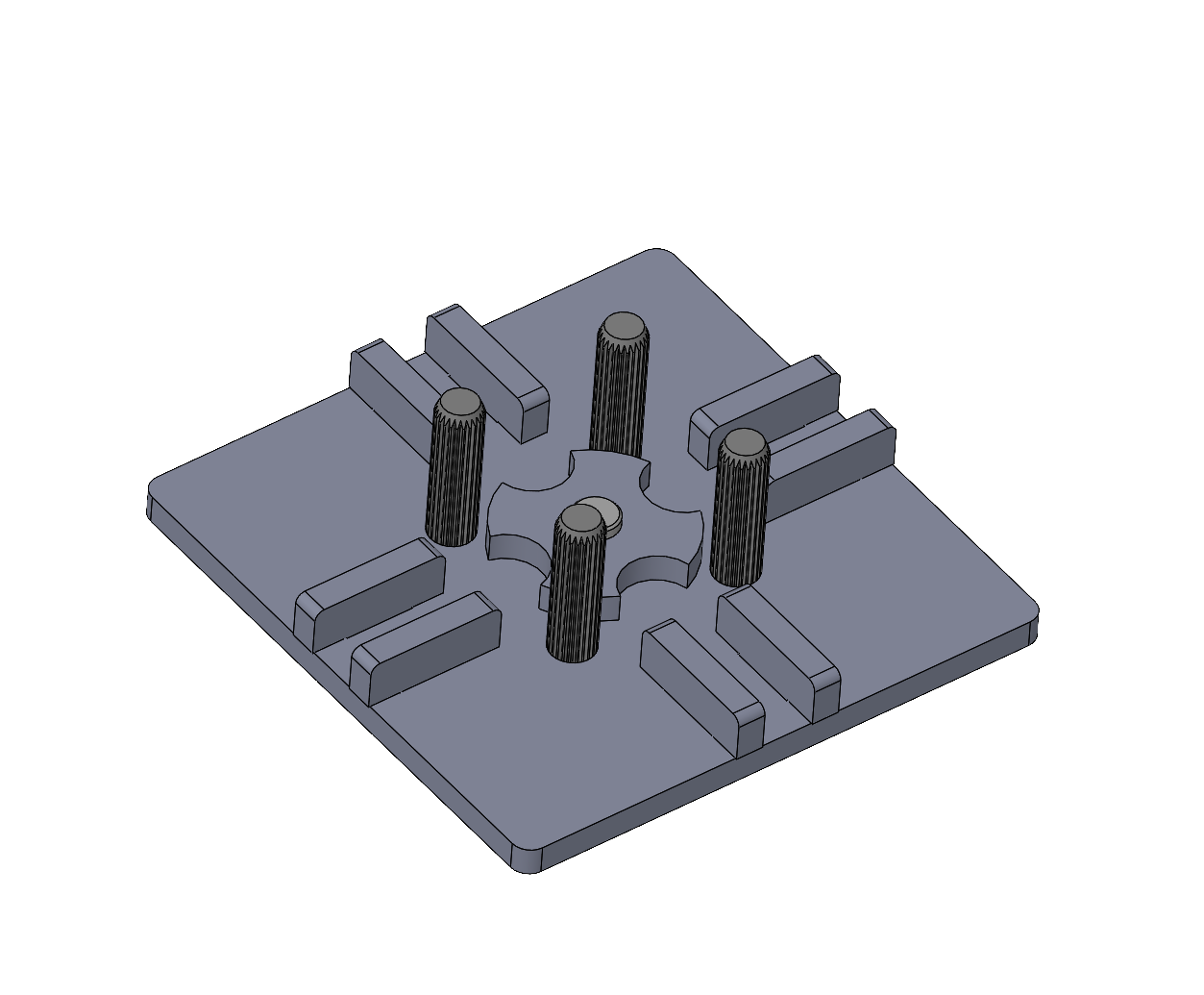
example-3.SLDASM: this tile demonstrates a combination of laser-cut joinery, standard 3/8 inch wooden dowel pins, and a pivoting laser-cut ‘spinner’ pivoting on a standard clevis pin.
Material and Tool Constraints
Every practical design needs to consider the tools and materials at the outset. The abstracted idea may be amenable to implementation using different fabrication methods, but the specific design invariably makes deep assumptions about the means.
For this assignment, please assume you would fabricate all parts from laser-cut 6 mm plywood. This is a versatile material which we use a lot for physical prototyping. If you are not familiar with laser-cutting, please see the IDeATe Laser Cutter Guide. Here are specific assumptions:
The tile should fit into a 120 mm square. Marbles should be able to enter or exit at the midpoint of one or more edges.
We will use 3/8 inch steel marbles. A 11 mm track width is recommended for generous clearance. For reference, we also stock 1/4 inch steel marbles, 5/8 inch glass marbles, and a limited supply of standard 27 mm pinballs.
The laser cuts along any 2D path, all the way through a flat piece of material. All parts can be drawn as a planar sketch extruded 6 mm thick.
The laser cuts with a kerf approximately 0.2 mm wide. There is no offset compensation, the beam travels straight down the middle of edge geometry, so all holes are approximately 0.2 mm overside, all outside diameters approximately 0.2 mm undersize.
My suggestion is to draw all parts using the desired final dimensions, but with features which are tolerant to cutting variation. This is generally a good practice which accommodates both normal material and fabrication tolerance.
If you have a hole which is a press-fit for a precision part like a ball-bearing, draw it undersize. The parts will overlap slightly in CAD, but once cut, the as-built dimensions will achieve the desired fit. E.g. for a ball-bearing with a 5/8 inch OD, the nominal exact hole would be 15.875 mm, so drawing it as 15.5 mm should result in an as-built hole about 15.7 mm, which is acceptable for a steel-into-plywood press-fit. (N.B. This would be too tight for steel-into-steel, but plywood is forgiving.)
My recommendation for making tabs which fit into slots:
Draw rectangular slots 6.2 mm wide. These will cut approximately 6.4 mm wide to accommodate variation in material thickness. My own habit is to draw the length as an integer, e.g. 15 mm long.
Draw the tabs as a trapezoidal shape to wedge into the slot. E.g., I draw my tabs for 15 mm slots as a trapezoid which is 6 mm high, with each edge sloped 2 degrees off the perpendicular (total of 4 degrees included angle), and the tip dimensioned 15.2 mm. The tip will cut at approximately 15.0 mm wide and freely fit into the slot, but the wider root of the tab will be a a press-fit. Adjacent to the tab (coming off the root) should be at least a few millimeters of edge which will make face contact around the slot to set a definite insertion depth.
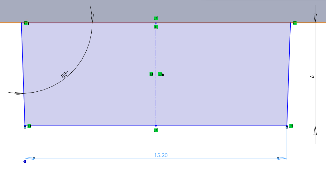
Trapezoidal profile for a laser-cut tab to fit into a laser-cut 15.0 x 6.2 mm slot, both in 6 mm plywood.
Include a tab centerline to use for locating the tab. I recommend center-to-center dimensioning for both tabs and slots to keep the details of the tolerancing out of the design logic.
Laser-cut edges are not perfectly vertical, there is a subtle slope whose exact shape and angle depend on the focal length and calibration of the lens. A well-designed part has a shape and fit which tolerates slightly non-square edges.
The laser can cut sharp inside corners (unlike milling tools). For our purposes, this is generally fine, but sharp corners are stress concentrations which can induce fracture under high loading. This does become a concern when creating press-fits using brittle acrylic parts.
Deliverables
Live in-class demo of your tile.
A short report posted to the course site including:
a zip of your SolidWorks files
a photo and/or brief video
a short text statement reviewing your intent and outcomes
Challenges
If you would like to explore more, please consider the following optional challenge question:
How would you perform computation mechanically using marbles? The marbles could serve as the power source and data transmission. Information could be stored either by marble location or the position of mechanical elements.
Ideas: