Flat-Pack Joinery
Joinery refers to techniques for rigidly connecting individual parts to build a structure. Moving connections are treated separately.
Our most common prototyping material is laser-cut 6 mm plywood. The process results in flat parts with prismatic shapes in which all cuts are fully through the material. These parts typically join at right angles. The design of these structures is informally called flat-pack because an entire assembly could begin as a box of flat parts.
The following discussion makes a few specific assumptions:
The laser cuts along any 2D path, all the way through a flat piece of material. All parts can be drawn in CAD as a planar sketch extruded 6 mm thick.
The laser cuts with a kerf approximately 0.2 mm wide. There is no offset compensation, the beam travels straight down the middle of edge geometry, so all holes are approximately 0.2 mm overside, all outside diameters approximately 0.2 mm undersize.
My suggestion is to draw all parts using the desired final dimensions, but with features which are tolerant to cutting variation. This is generally a good practice which accommodates both normal material and fabrication tolerance.
Laser-Cut Tabs and Slots (Tenson and Mortise)
A useful method for creating a perpendicular connection is to cut tabs in one part edge when fit into slots in the face of the other part. In woodworking terminology, the ‘tab’ is called a tenon, and the ‘slot’ is called a mortise.
My recommendations for making tabs which fit into slots, assuming 6 mm laser-cut plywood:
Draw rectangular slots 6.2 mm wide. These will cut approximately 6.4 mm wide to accommodate variation in material thickness. My own habit is to draw the length as an integer, e.g. 15 mm long.
Draw the tabs as a trapezoidal shape to wedge into the slot. E.g., I draw my tabs for 15 mm slots as a trapezoid which is 6 mm high, with each edge sloped 2 degrees off the perpendicular (total of 4 degrees included angle), and the tip dimensioned 15.2 mm. The tip will cut at approximately 15.0 mm wide and freely fit into the slot, but the wider root of the tab will be a press-fit. Adjacent to the tab (coming off the root) should be at least a few millimeters of edge which will make face contact around the slot to set a definite insertion depth.
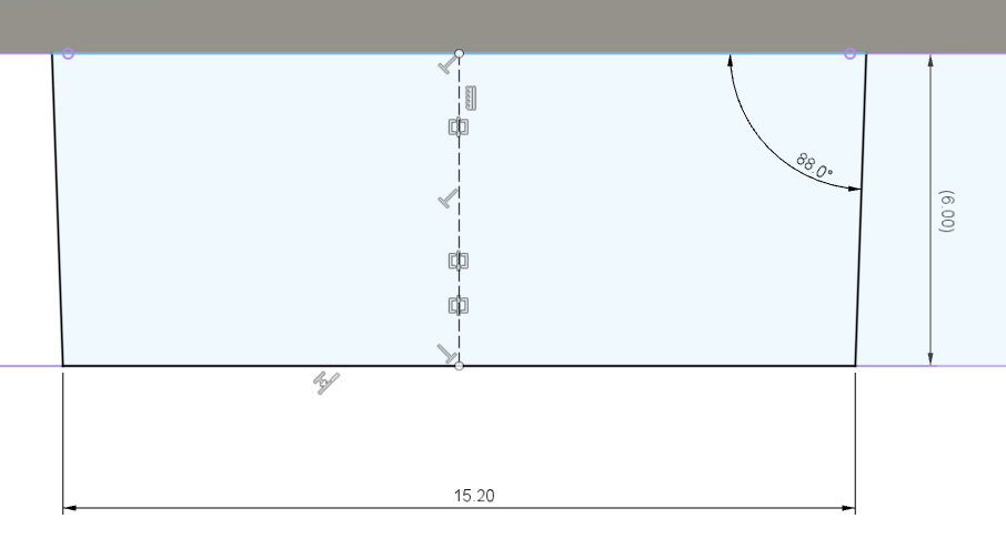
Trapezoidal profile for a laser-cut tab to fit into a laser-cut 15.0 x 6.2 mm slot, both in 6 mm plywood.
In tab CAD sketches, I recommend including a tab centerline to use for locating the tab. Center-to-center dimensioning for both tabs and slots keeps the details of the tolerancing out of the design logic.
These tab and slot connections can be assembled by lightly hammering the parts together. Glue can be added to the tab prior to assembly if more pullout strength is needed, but in many cases isn’t needed if the overall structure provides enough constraint.
Laser-Cut Captive-Screw Mortise and Tenon
The purpose of a captive-screw connection is to create a butt joint clamped by a screw and nut within the plane of one of the two parts. The primary advantages are a joint which can be tightly clamped with a wide tolerance for variations in material thickness. It can also be easily disassembled and re-assembled, and the fasteners re-used many times. The primary disadvantages are the weight and cost of steel fasteners, the need to provide access to the screw head and nut for tightening, and the weakness to resisting rotation around the screw axis.
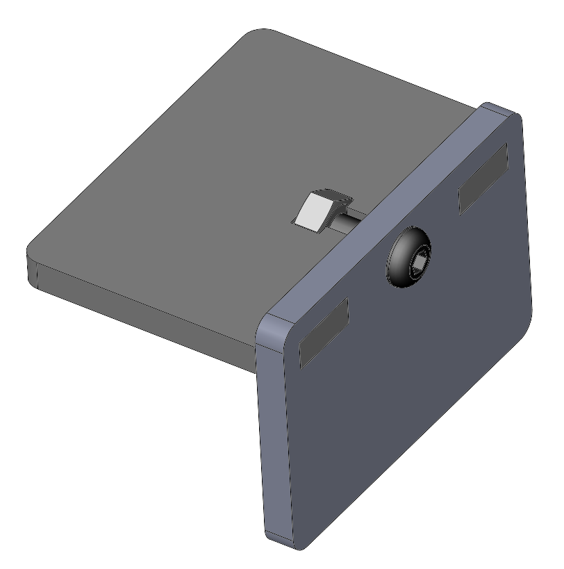
Example of a captive-screw connection incorporating two mortise and tenon joints. The captive screw slot is laser-cut to tightly fit a 1/4-20 nut.
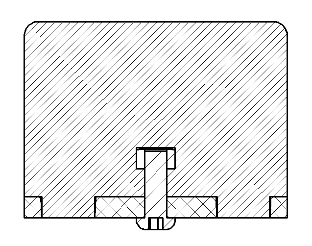
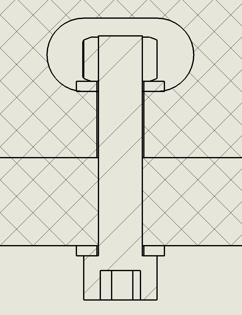
Section view showing the two tenons pressed into mortises and the clamping screw.
This captive-screw joint includes a pair of press-fit mortise and tenon joints. Each tenon tongue is slightly tapered and can be tapped into the corresponding mortise slot. The screw clamps the two parts firmly together.
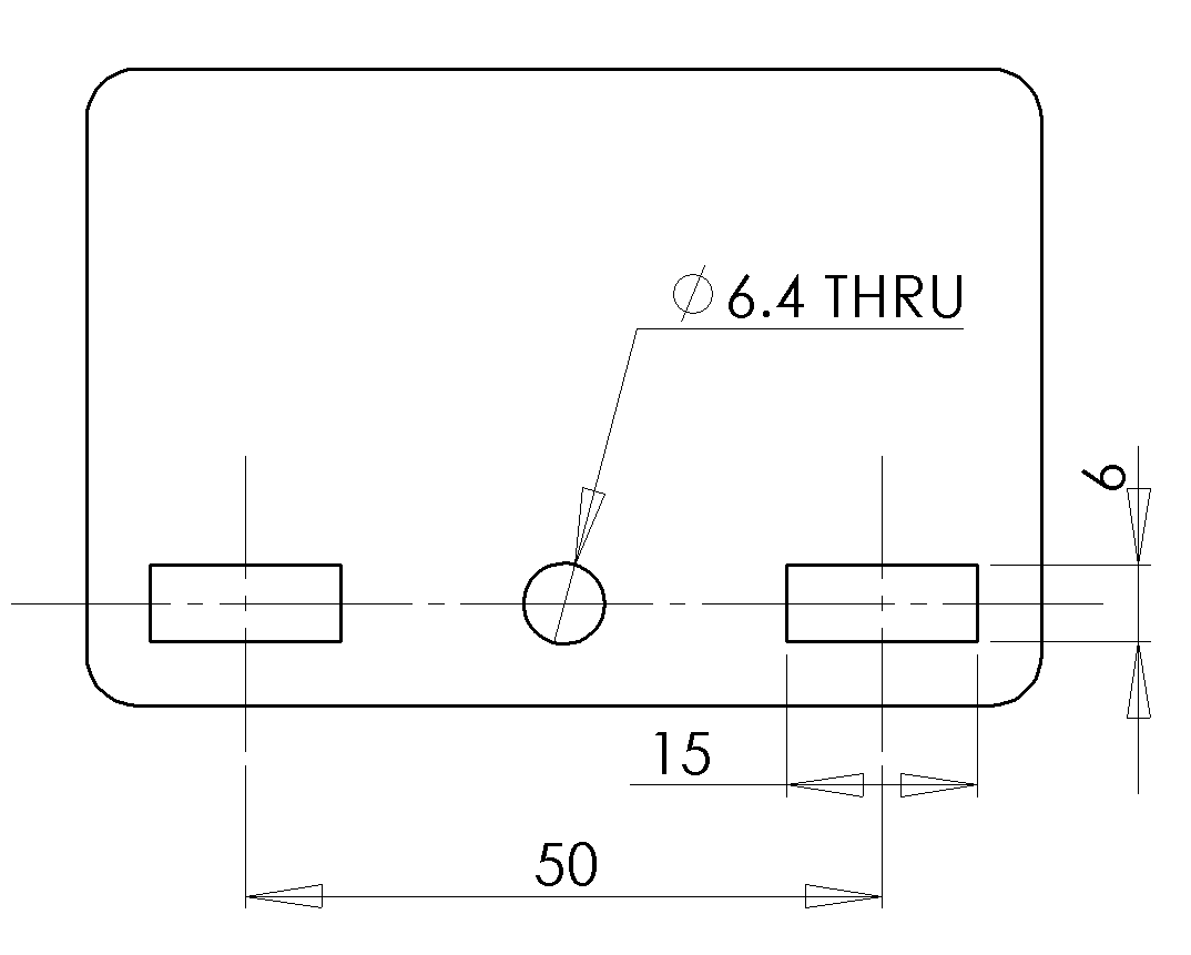
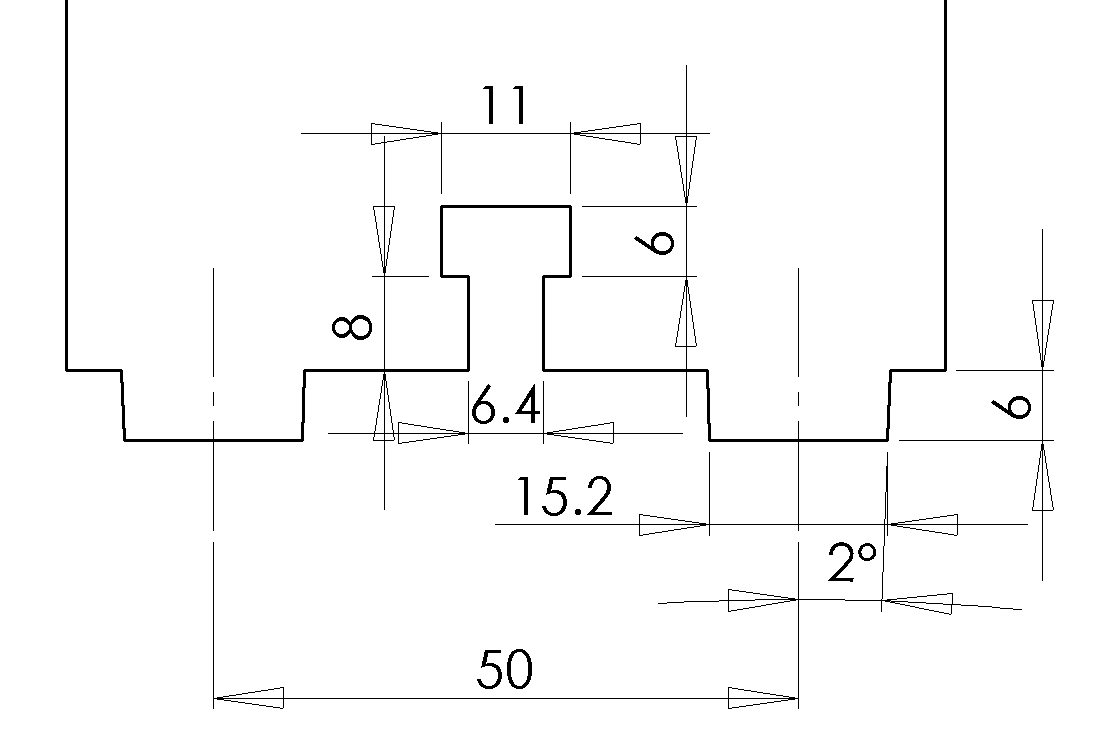
Typical dimensions for the features are shown below, assuming the use of 6 mm plywood stock and a 3/4” long 1/4-20 screw. Please note the 2 degree taper on the tenons.
CNC-Cut Captive-Screw Joinery
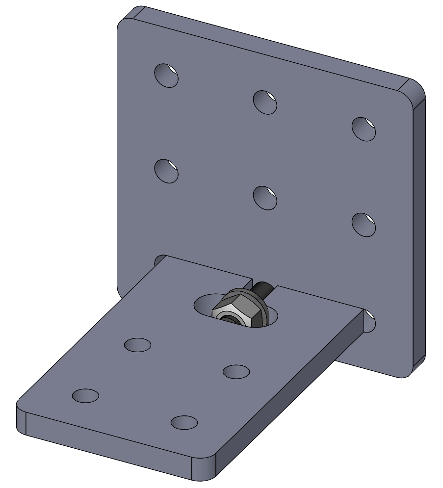
Example of a captive-screw connection joining two plates at a right angle.
This example uses a circular slot geometry to maintain compatibility with milling and routing; the feature can be contour-routed with a 6.35 mm (1/4”) or smaller end mill. This approach takes more space than a tightly-fitting square slot design possible with the laser cutter. But a side benefit is avoiding stress concentrations at sharp inside corners. This example lacks the tenons and is susceptible to rotating out of place unless further constraint is provided.
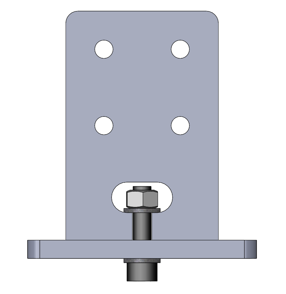
Side view of a captive-screw connection joining two plates at a right angle.
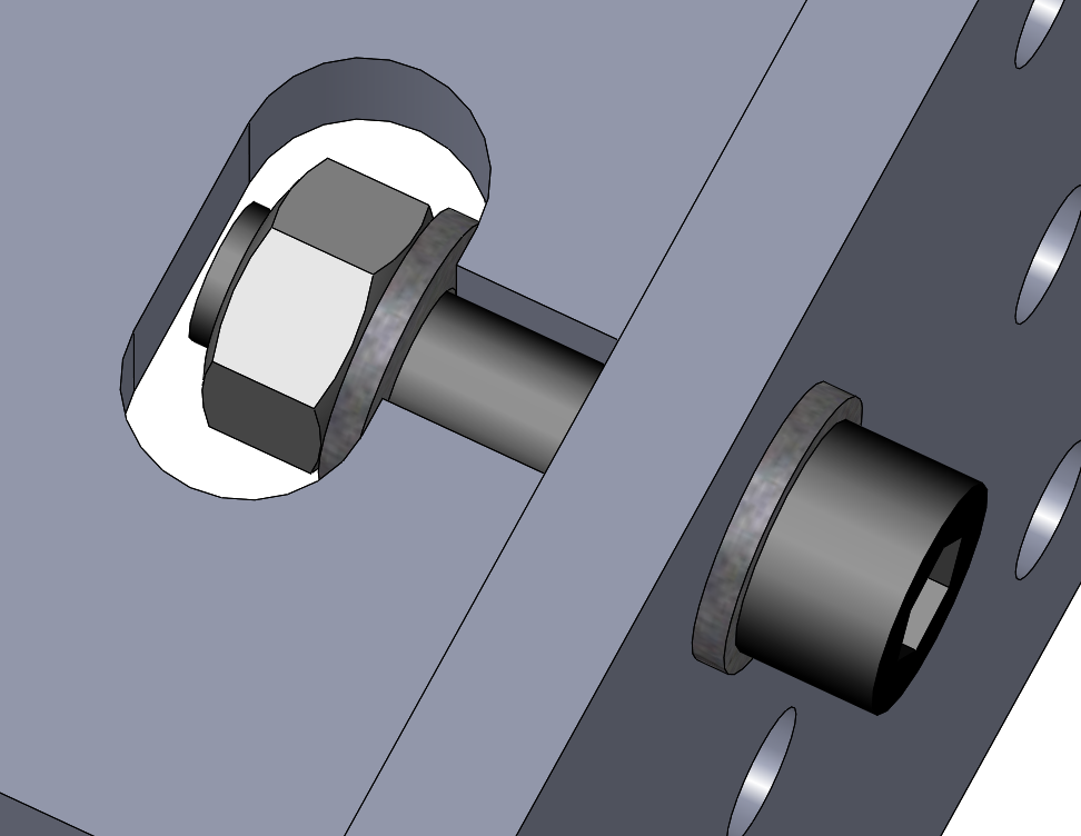
Detail of a captive-screw connection joining two plates at a right angle.
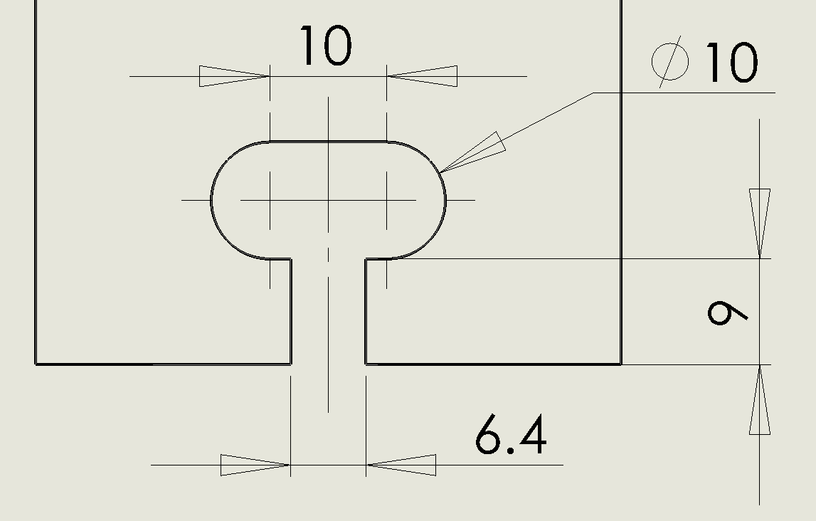
Typical dimensions for a captive-screw slot for a M6 or 1/4-20 screw. All dimensions are in millimeters.
Following are examples of captive-screw joints for different stock thicknesses. Washers are included to distribute the nut and head forces over wider faces of each end of the slot, although in some use cases they may be omitted:
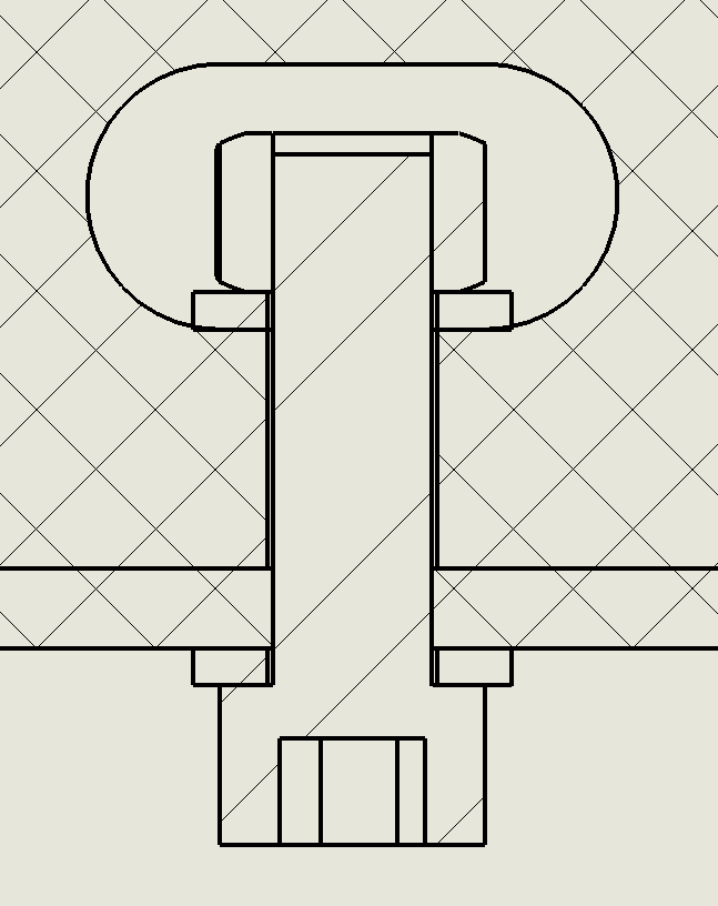
The screw lengths are as follows:
Stock
Screw
3 mm
M6 x 20
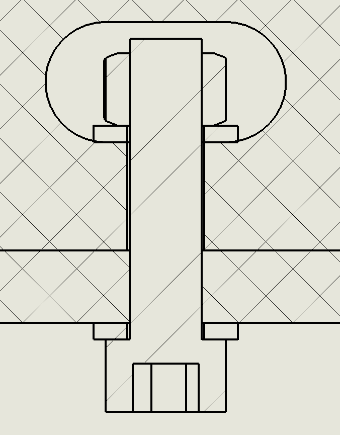
6 mm
M6 x 25
9 mm
M6 x 25
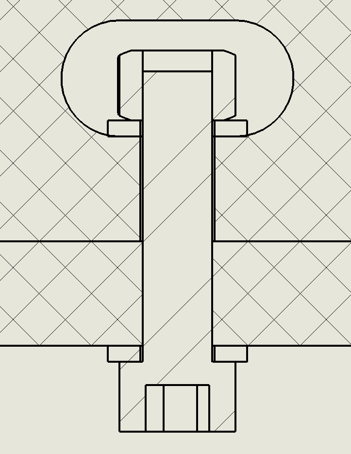
12 mm
M6 x 30
Note that the screw has a partial fit on the nut for the 9mm case, which could be improved by omitting a washer.
Standard Hole Patterns
(need sketch or photos for: standard hole pattern, lap-joint slot, etc.)
Other Online Resources
50 Digital Joints (mostly for 3-axis CNC, some for laser) (alternate link)(alternate link)(alternate link)