Voltage Dividers
Many of our sample circuits use a fundamental construction of series resistances called a voltage divider. In this section we review the general form of this circuit and relate it to the specific examples. It may be helpful to review the general electrical theory summary in Summary Guide: Basic Circuits.
General Resistor Divider
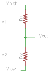
The circuit at left shows two resistances connected in series between voltages \(V_{high}\) and \(V_{low}\). We will assume that no current flows out \(V_{out}\), i.e., it is connected only to infinite resistance.
Each resistor follows Ohm’s Law: \(V = i * R\). This idea can be understood in several ways:
a voltage across a resistor will cause a current to flow through it: \(i = V / R\)
a current through a resistor will induce a voltage drop across it: \(V = i * R\)
the resistance is defined by the observed ratio of voltage drop to current flow: \(R = V / i\).
These are not different facts, just restatements of the same underlying equilibrium of electricity flowing through a resistor.
The two resistors in series form a single current pathway: since we assume no current flows out \(V_{out}\), the current \(i\) through R1 must be the same as through R2, it has nowhere else to go.
Since the current is the same for both resistors, the voltages across the resistors are:
\(V_1 = i * R_1\)
\(V_2 = i * R_2\)
Voltages in series add. The applied voltage difference is \(V_{high}-V_{low}\), so:
\(V_{high}-V_{low} = V_1 + V_2\)
\(V_{high}-V_{low} = i * (R_1 + R_2)\)
Considering the circuit as a whole, we can apply Ohm’s Law to see that the voltage difference is related to the total loop resistance \(R\):
\(V_{high}-V_{low} = i * R\)
Which proves that series resistances add together:
\(V_{high}-V_{low} = i * R = i * (R_1 + R_2)\)
\(i * R = i * (R_1 + R_2)\)
\(R = R_1 + R_2\)
The voltage at the the output can be determined just from the voltage drop across R2:
\(V_{out} = V_{low} + V_2\)
\(V_{out} = V_{low} + i * R_2\)
\(V_{out} = V_{low} + ((V_{high}-V_{low})/(R_1 + R_2)) * R_2\)
\(V_{out} = V_{low} + (V_{high}-V_{low}) * (R_2/(R_1 + R_2))\)
Grounded Resistor Divider
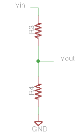
We most commonly connect \(V_{low}\) directly to ground as shown in the second diagram. So the general form simplifies:
\(V_{high}=V_{in}\)
\(V_{low}=0\)
\(V_{out} = V_{in} * R_4/(R_3+R_4)\)
Note that \(V_{out}\) is always lower than \(V_{in}\); the divider always scales the input voltage down.
Also note that since a continuous current flows through the resistors, the divider dissipates power at a constant rate:
\(P = i * V_{in}\)
\(i = V_{in} / (R_3+R_4)\)
\(P = V_{in}^2 / (R_3+R_4)\)
Power is the product of the voltage and current. In a resistor, this electrical energy is transduced into heat.
Divider with a Switch
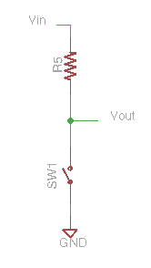
An open switch has infinite resistance; a closed switch has zero resistance. The recommended practice for connecting a switch to a digital input is to use a resistor as the upper leg of a voltage divider. Then when the switch is open:
\(V_{out} = V_{in} * R_{sw}/(R_{sw}+R_5)\)
\(R_{sw} = ∞\)
\(V_{out} = V_{in} * ∞/(∞+R_5)\)
\(V_{out} = V_{in}\)
When the switch is closed:
\(R_{sw} = 0\)
\(V_{out} = V_{in} * 0/(0+R_5)\)
\(V_{out} = 0\)
A common error is to just connect a switch directly between +5V and an input without a bias resistor. When the switch is closed, the input goes high, but when the switch is open, the input is not connected to anything: it is said to be floating and has an indeterminate value. The Arduino can still read the pin but the result is unpredictable, often leading to erratic behavior of the system.
Divider with a Photoresistor
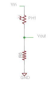
This photocell circuit is drawn in the ‘non-inverting’ configuration in which a brightness increase causes a voltage increase.
\(V_{out} = V_{in} * R_6/(R_{ph}+R_6)\)
In darkness:
\(R_{ph}\) will be large
\(V_{out}\) will be low.
As the light increases:
\(R_{ph}\) will decrease
\(V_{out}\) will rise
LED Ballast as Divider
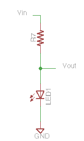
An LED does not act as a linear resistor and so the linear equation above for \(V_{out}\) does not hold. However, the following remains true:
the current through the resistor and LED must be the same: \(i_7 = i_{LED}\)
the total voltage difference is the sum of the LED and resistor voltages: \(V_{in} = V_7 + V_{LED}\)
In practice, \(V_{out}\) will be the same as \(V_{in}\) for voltages lower than the LED threshold, and then \(V_{out}\) will not rise much above the threshold voltage. In effect, the LED acts as a primitive voltage regulator by increasing current flow steeply as the voltage increases; this current increase raises the voltage drop across the ballast resistor so the LED voltage drop stays relatively constant.
Choosing Values in Circuits for Resistive Sensors
A common problem in setting up a divider circuit is choosing useful resistance values. There are a couple of general heuristics to consider:
If the values are too small, a lot of power will be dissipated in the divider resistors.
If the values are too large, the currents will be small, so the assumption that \(i_{out}\) is zero might break down. An Arduino has a high input impedance but it isn’t actually infinite, so using very large input resistors will increase the effects of noise.
For a given resistive sensor, the range of resistances is a property of the range of physical conditions to observed. So the key choice becomes the ratio of sensor resistance to bias resistance over the range of interest.
A good general heuristic is to choose resistor values which are approximately equal at the midrange of inputs.
However, sometimes it is possible to physically configure the sensor to change its operating point: photosensors can have lenses or apertures to collect more or less light, potentiometers can have linkages to increase or decrease mechanical travel.
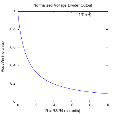
It may be useful to consider the following plot which shows the normalized response of a voltage divider. The response can be normalized to a dimensionless form as follows:
\(V_{out} = V_{in} * R_4/(R_3+R_4)\)
\(V_{out}/V_{in} = {R_4 \over (R_3+R_4)}\)
\(V_{out}/V_{in} = {(R_4/R_4) \over (R_3/R_4) + (R_4/R_4)}\)
\(V_{out}/V_{in} = {1 \over (R_3/R_4) + 1}\)
The vertical axis of the plot shows \(V_{out}/V_{in}\), i.e. the ratio of output to input voltage (a number with no units, i.e. dimensionless). The horizontal axis shows \(R_3/R_4\), the dimensionless ratio of resistances.
References
Other Files
EAGLE file:
voltage-dividers.sch
Comments
Many variable resistors are the three-terminal form called a potentiometer in which a continuous strip of resistive media is contacted by a wiper. This forms a voltage divider in which the resistances of the upper and lower legs are continuously variable, but the total loop resistance is constant.
Voltage dividers are an essential part of op-amp circuits in which resistor networks are used to set the offset, gain, and filter characteristics.