In this exercise we will design a new marble run tile incorporating both a hobby
servo actuator and a photoreflective interrupter to sense a moving marble. This
is similar to the Exercise: Actuated Marble Run Tile and could be treated as
an iteration of a previous design with added sensing.
The main objective of this exercise is implementing a system blending the
passive physics of a marble track, sensor input feedback, and actuated
mechanism. The connection between input and output will be made via a
computational process on a Pico.
Please choose design goals commensurate with your mechanical design experience
and CAD skills. But please consider how to make the device versatile enough to
allow different system behaviors to be implemented via software revisions.
For this exercise we will primarily use laser-cut plywood. If you wish to use
3D printing for one or more parts, please consult with the instructor.
The overall objective of this exercise is to design and fabricate a small marble
run track which incorporates both a hobby servo actuator and a reflective
photointerrupter. This may be a standalone run or include inputs and outputs so
it may be assembled on a sloped table with other active or passive tiles.
The goals of this exercise are that you should be able to:
Conceive and sketch a simple mechanism including ball pathways, sensor
placement, moving elements, actuator mounting, and motion transmission.
Create 3D parts from 2D CAD sketches:
that use parametric constraints and dimensions to capture design intent
that support iterative design modification
compatible with the limits of the laser-cutting process
Fabricate, assemble, and test a mechanism combining laser-cut plywood,
standard parts, hobby servo, and sensor wiring.
Sample files are provided on the assumption that students will go farther given
a stronger foundation, so these are provided for you to examine and use as
starting points. But if you use one as a template, please be mindful that you
add meaningful development, not just tweak it trivially.
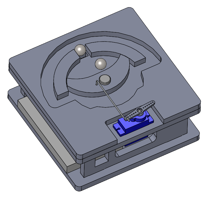
Example of a marble run tile with both an actuator and sensor. This design
is self-contained without entry or exit ports. The central gate moved by the
servo via a wire linkage to capture a ball or allow it to exit out the side
channels. The sensor is placed in the narrow upper channel. The design
includes a base to create a shelf for the electronics, clearance for the
servo body, and the option of using a longer shaft with a second bearing.
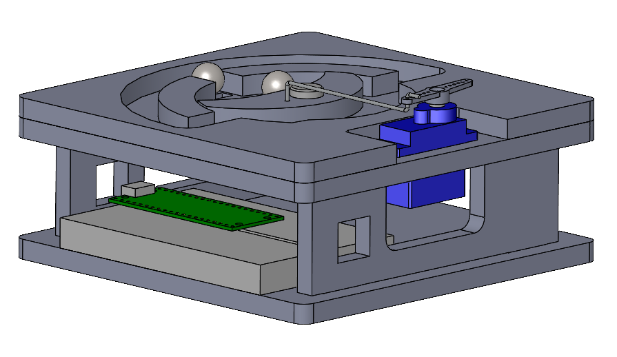
Same design with a lower viewpoint to show the placement of the Pico on a
medium breadboard. The vertical struts use 15 mm tabs to assemble into slots
in the base and playfield.
Please fabricate all parts from laser-cut 6 mm plywood, unless you get
instructor permission to fabricate 3D printed parts.
The tile should fit into a 120 mm square. Entry/exit ports should be located
at the midpoint of one or more edges. The sample design places the playfield
surface 42 mm above the ground plane.
We will use 3/8 inch steel marbles. A 11 mm track width is recommended for
generous clearance.
Please use a linkage or other indirect drive to move the mechanism. The servo
horn is not intended for collisions or heavy masses.
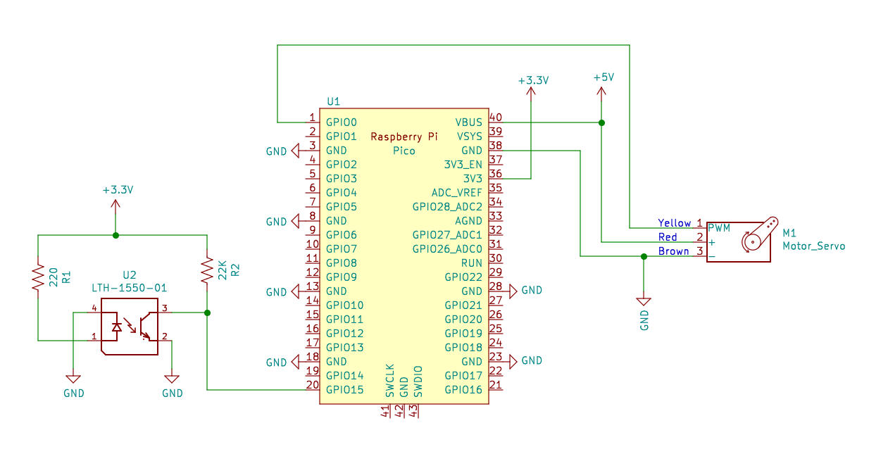
Recommended circuit for the exercise. The photointerrupter must be powered
from the 3.3V supply on pin 36 to limit the Pico input voltages. The hobby
servo must be powered from the 5V supply on pin 40 for sufficient motor
current. The specific GPIO pins match the sample code, but could be changed
to any other GPIO pins.
If you would like to explore more, please consider the following optional
challenge question:
How much information can be gleaned from a single sensor? It may only be a
single bit, but it changes in a pattern over time, and the semantics of that
pattern depend heavily on the placement within the marble pathways.