Connectors
We use an abundance of components for temporarily or permanently creating electrical circuits. This page includes notes on some specific components we use in the lab, and is by no means comprehensive.
Modular Microcontroller Systems
Several manufacturers have sought to create modular part systems for easy connection of microcontrollers to breakout boards. As is often the case, they are similar but not compatible. (See https://xkcd.com/927/ for a commentary on this process.)
Grove System
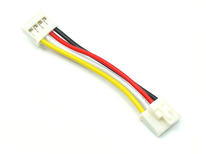
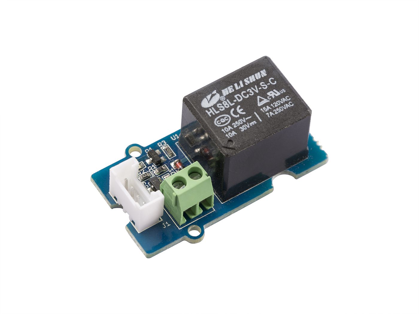
The Grove System from Seeed Studio uses a four-pin latching connector. It supports multiple signal types, including I2C, Analog I/O, digital GPIO, and PWM. The pin functionality is not fixed and the user must take care to observe part compatibility, as can be seen below in the example pinouts.
The cables use female connectors to mate with male board headers. The pin spacing is 2 mm. The cables are not directional, both ends have the same wire order. The connectors are keyed for orientation and include a locking tab. The actual connector might be a proprietary NS-Tech 1125S-4P A2005 (not verified). Cables are available in different standard lengths. We do not have pins, housing, or a crimper which can assemble custom cables.
The typical I2C usage is as follow:
Pin |
Color |
Signal |
|---|---|---|
1 |
Black |
Ground |
2 |
Red |
VCC, 3.3V or 5V |
3 |
White |
SDA, I2C Data |
4 |
Yellow |
SCL, I2C Clock |
Sensors with analog outputs appear to use:
Pin |
Color |
Signal |
|---|---|---|
1 |
Black |
Ground |
2 |
Red |
VCC, 3.3V or 5V |
3 |
White |
NC (no connect) |
4 |
Yellow |
OUT, analog sensor output |
Servos with PWM inputs appear to use:
Pin |
Color |
Signal |
|---|---|---|
1 |
Black |
Ground |
2 |
Red |
5V motor power |
3 |
White |
NC (no connect) |
4 |
Yellow |
PWM, servo command input |
The Cytron MD13S motor driver uses a Grove connector pinout:
Pin |
Color |
Signal |
|---|---|---|
1 |
Black |
Ground |
2 |
Red |
NC (no power to driver) |
3 |
White |
PWM driver input |
4 |
Yellow |
DIR driver input |
The Maker Pi Pico baseboard includes six Grove connectors:
Pin |
Color |
Signal |
|---|---|---|
1 |
Black |
Ground |
2 |
Red |
3.3V |
3 |
White |
GPIO (variable function) |
4 |
Yellow |
GPIO (variable function) |
Qwiic
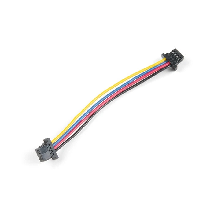
The Qwiic connect system from SparkFun uses small four-pin JST connectors to carry I2C between modules. The connectors are polarized but not locking. Most components have two connectors to enable daisy-chaining the I2C bus from module to module. It is also possible (within reason) to fork the bus using small hubs. The Quiic connectors use a 1 mm pin spacing so are smaller than Grove. Cables are available in different standard lengths. We do not have pins, housing, or a crimper which can assemble custom cables.
This system has standarized on 3.3V I2C digital bidirectional communication. This reduces the chance of wiring incompatibility, although please note I2C devices need distinct addresses and may not be compatible together. Qwiic devices should not be attached to STEMMA QT using 5V, only 3.3V.
The typical I2C usage is as follow:
Pin |
Color |
Signal |
|---|---|---|
1 |
Black |
Ground |
2 |
Red |
VCC, 3.3V |
3 |
Blue |
SDA, I2C Data |
4 |
Yellow |
SCL, I2C Clock |
STEMMA QT
The STEMMA QT connect system from Adafruit uses four-pin JST connectors to carry I2C between modules. There are two STEMMA connector sizes in use, a JST PH at 2.0 mm pitch and a JST SH at 1.0 mm pitch. The QT products use the smaller SH connectors and are compatible with Qwiic.
The electrical difference is that STEMMA QT allow for 5V operation, not just 3.3V. STEMMA QT products are required to accept 5V. Users of 5V microcontrollers should check voltage compatibility if mixing product families.
STEMMA
The STEMMA connect system from Adafruit includes analog, digital, and I2C interfaces using 3 and 4 pin JST connectors.
The larger 2 mm pitch STEMMA PH connectors follow a different wiring convention than the smaller QT SH connectors, instead they are similar to Grove. E.g, the I2C pinout is reversed:
Pin |
Color |
Signal |
|---|---|---|
1 |
Green |
SCL |
2 |
White |
SDA |
3 |
Red |
V+ |
4 |
Black |
GND |
It appears that 4-pin STEMMA connectors (2 mm pitch) can connect to Grove board connectors, although they lack the latch.
goBILDA Encoders
The goBILDA servomotors use a four-pin JST XH connector (2.5 mm pitch) for the encoder output using the following pinout:
Pin |
Color |
Signal |
|---|---|---|
1 |
White |
B phase output |
2 |
Blue |
A phase output |
3 |
Black |
GND |
4 |
Red |
VCC, 3.3 to 5V |
goBUILDA offers a cable to connect this to a 4-pin JST PH compatible with 2 mm STEMMA (regular, not QT):
Pin |
Color |
Signal |
|---|---|---|
1 |
Blue |
A phase output |
2 |
White |
B phase output |
3 |
Red |
V+ |
4 |
Black |
GND |