MOSFET Transistor Drivers
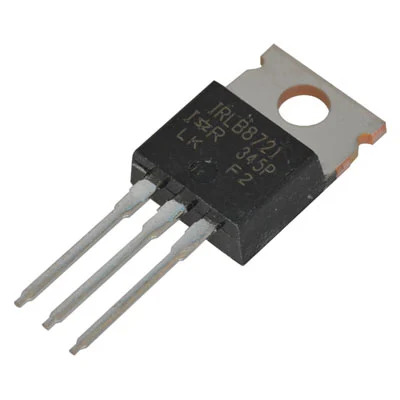
A MOSFET is a transistor which can control significant current in one direction using a very low current control signal. We use them for driving gearmotors, solenoids and relays.
The driver circuit is unipolar or single-ended meaning that the current it delivers only flows in one direction. This is primarily relevant to DC motors for which the direction of rotation is controlled by the direction of the current through them; these circuits can stop and start a DC motor but not change its direction. The action of solenoids, relays, and incandescent lamps only depends on the magnitude of the current, not its direction. Large LEDs only conduct in one direction.
Since the transistors in these sample are only ever fully ON or fully OFF, we can understand it simply as a form of controlled switch, as explained below.
The circuit uses a digital output. The basic operation is normally binary, either on or off, but pulse-width modulation can vary the average energy delivered by rapidly cycling the signal on and off. For many devices, this produces a linear response, i.e., the DC motor speed varies in proportion to the duty cycle of the PWM signal.
We will also use relays, which are mechanical switches controlled by an solenoid coil. Some relays can switch very high power loads, but note that the relay coil may itself require a driver circuit, resulting in two stages of power amplification: a driver to amplify a logic output to drive the coil, and the relay to switch the actuator load.
This circuit can operate devices using higher voltages than are safe for microcontrollers to encounter, so please be careful with wiring discipline. Note the there are alternatives that offer more electrical isolation by using an opto-isolator to connect to the MOSFET. Note also that relays provide high isolation between the coil circuit and the contact voltages, limiting the chance of dangerous voltages frying the logic.
MOSFET Transistors
A transistor is a type of three-terminal semiconductor component which allows a control current or voltage at the base or gate terminal to affect the current flowing through the device. A MOSFET is a particular type of transistor with very high current gain; the gate input has very high impedance, such that a gate voltage with very little current can control the current flowing between the source and drain. This makes it very convenient for interfacing logic-level signals to loads such as motors.
MOSFETs have a linear range in which the current is proportional to the gate voltage, but this exercise will use it in a saturation mode in which it is either on or off. MOSFETS come in both P-channel and N-channel varieties exhibiting different polarities; this exercise uses an N-channel MOSFET in which a small positive gate voltage relative to the source terminal will cause a positive current to flow from drain to source, activating the motor.
MOSFETs have very low forward voltage, i.e., the voltage drop across the source and drain can be very low, meaning there is very little power dissipated for a given current.
Pico with MOSFET
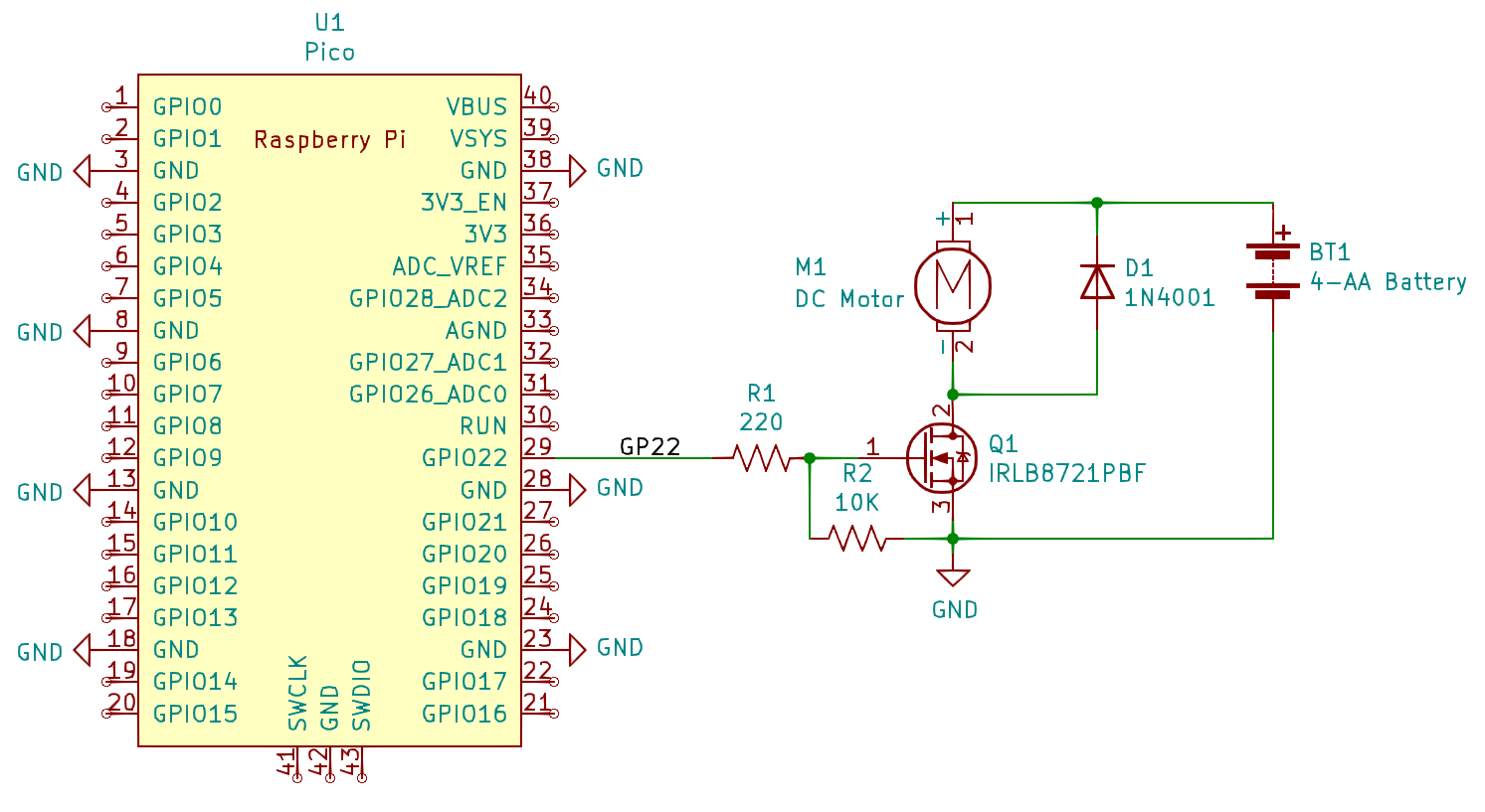
This example use a IRLB8721PbF N-Channel MOSFET transistor as the driver, Lab Part 8721.
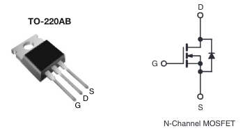
A reference image to the MOSFET package we will use is below. Please note that the gate pin G is actually one of the outside pins, even though the schematic symbol shows it in the center. For this N-Channel MOSFET, the source pin S is usually connected to ground, and the drain pin D to the load.
Comments on Bipolar Transistors
You may find reference circuits using the TIP120 Darlington transistor, which is actually two transistors in one package, and we do stock some in the lab. There isn’t much reason to use these anymore; they are slightly cheaper than MOSFETs and more resistant to static dischage, but because they are bipolar junction transistors, they have a much higher intrinsic voltage drop which means they dissipate a substantial amount of heat.
The parts we will use with bipolar transistors are the ULN2003 or ULN2803, as described in Exercise: Multichannel Bipolar Transistor Driver. These combine 7 or 8 channels in one package, and the convenience of this can outweigh the thermal issues.
Comments
MOSFETS
MOSFETS are fast and silent. Modern MOSFETS can handle relatively high power loads with minimal dissipation. The parts are polarized, and driving an output with both positive and negative current (e.g. for directional control) requires multiple parts and steering logic, e.g. an H-Bridge configuration. The polarization also makes them unsuitable for controlling AC circuits. More details can be found on the data sheet for the IRF540 MOSFETs we stock in the lab.
Note that the MOSFET symbol includes a reverse-biased Zener diode which exists as a byproduct of the transistor structure. If the voltage across the MOSFET becomes sufficiently reversed, it will begin to conduct (“avalanche”) and can be destroyed. This circuit has no apparent negative voltages, however, the motor coil is an inductor which can create negative voltage spikes as it turns off. With larger motors in particular, it can be important to place a protective clamp diode around the motor which normally does not conduct but turns on to absorb large reverse voltages.