Motor Hubs
Our gearmotors combine a small DC motor with a gearbox to produce shaft rotation at a usable speed. The following examples demonstrate best practices for attaching loads to the shaft. For more details on motor mounting please see Motor Mounting.
Gearmotor Mounting
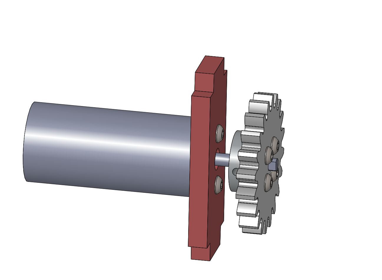
Gearmotor mounted to a panel with a laser-cuttable spur gear attached using a Pololu hub.
These examples all use our stock 25 mm gearmotor. The part combines a 6V DC motor at the back with a 25 mm diameter gearbox at the front. The shaft is 4 mm diameter with a flat. The motor mounting face includes two M3 threaded holes.
This example shows the only allowed mounting technique: clamping the full mounting face to a panel using two M3x10 screws. The panel hole pattern includes a 7 mm clearance hole for the motor shaft bushing and a pair of 3 mm screw holes symmetrically placed 17 mm apart.
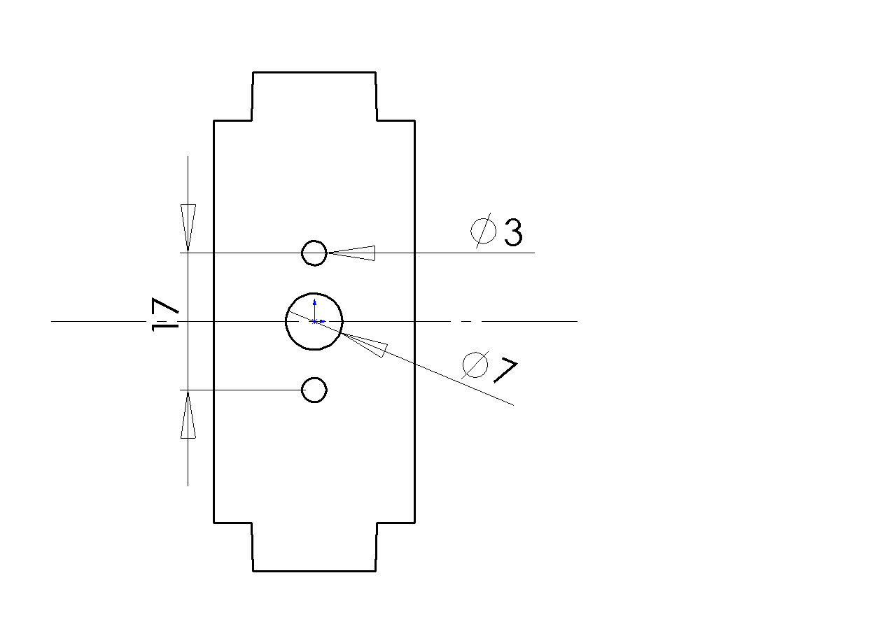
Hole pattern for mounting gearmotor to panel.
The figure also shows the use of a metal hub to connect the load to the shaft. This is the only practical way to make a reliable connection; wooden parts will invariably deform under load against the metal shaft and come loose. Please never use glue on any motors or motor shafts.
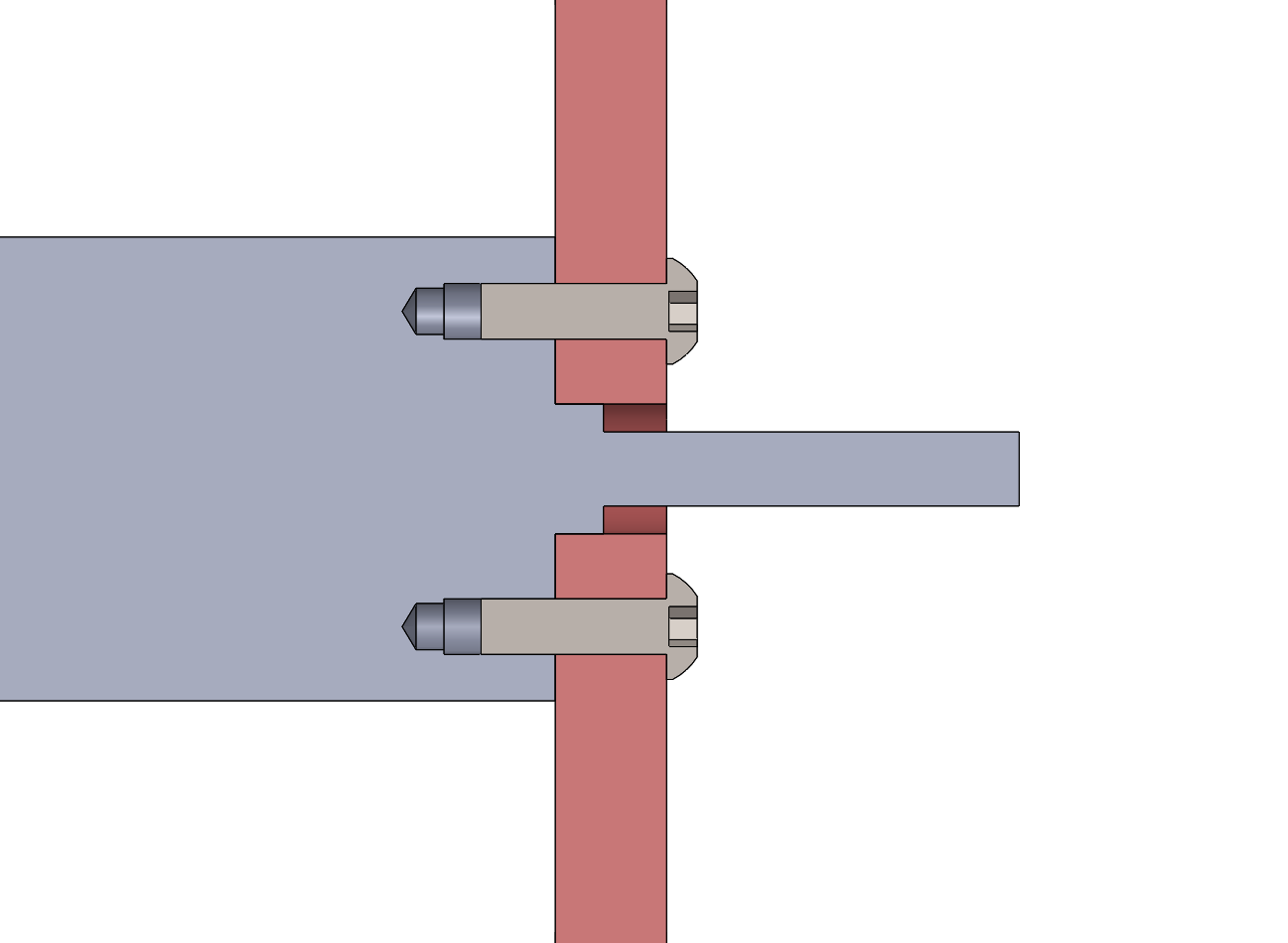
Section view showing the placement of the motor shaft bushing bearing inside a clearance hole in the panel.
Pololu hub
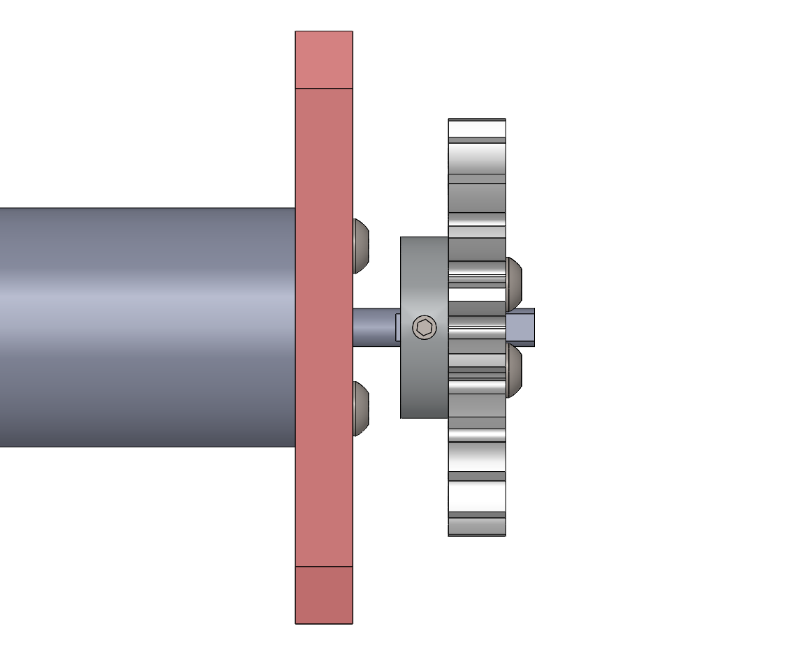
Gearmotor mounted to a panel with a laser-cuttable spur gear attached using a Pololu hub on the inside.
This particular configuration shows the attachment of a laser-cut spur gear to the motor using a Pololu 1997 hub as a coupler. The hub includes four M3 threaded holes so two or four M3x10 button-head cap screws can clamp the wooden gear to the hub.
In this version, the hub is placed closer to the motor, with the gear on the outside. The following version flips the gear closer to the panel to reduce shaft loads.
Please note that the gearmotor mounting has a specific assembly order: the mounting screws are concealed by the hub, so the motor must be installed in the panel first, then the hub and gear installed on the shaft.
The hub includes an M3 set screw which should be placed to press against the flat of the shaft. The reduces the chance the setscrew will mar the round surface of the shaft. The principle of the set screw is to press the cylindrical face of the shaft tightly against the closely fitting cylindrical bore to develop frictional contact across a large area opposite the set screw.
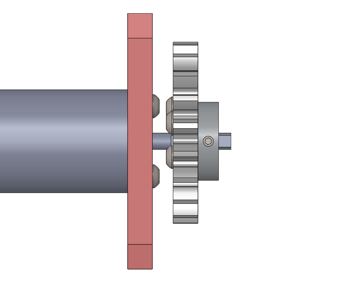
Gearmotor mounted to a panel with a laser-cuttable spur gear attached using a Pololu hub on the ouside.
Flange Hub
A newer hub part in the lab is the flanged hub. It has plain holes instead of threaded so the attachment to the gear uses M3 nuts.
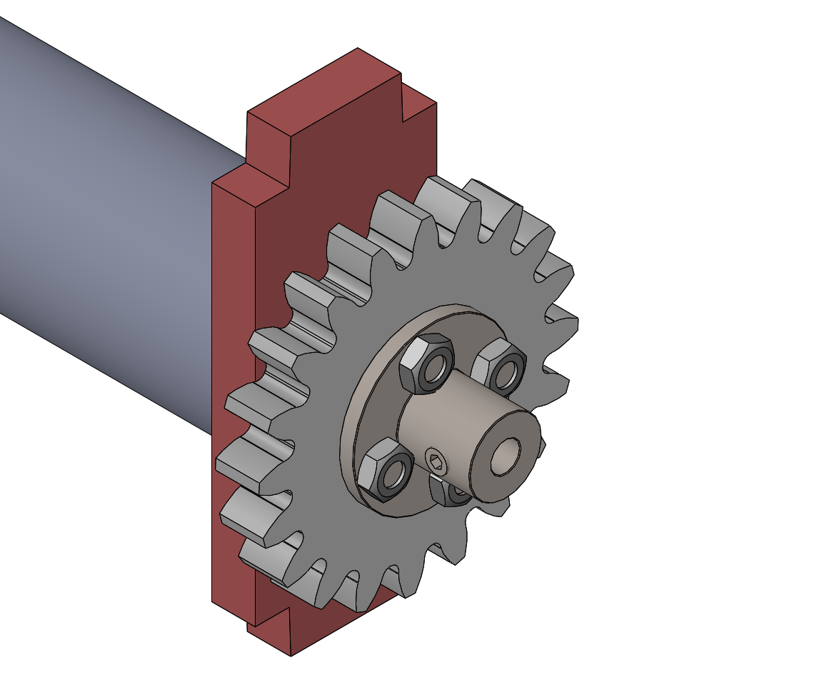
Gearmotor mounted to a panel with a laser-cuttable spur gear attached using a flange hub. This version requires M3 nuts on M3x10 button-head cap screws to clamp the gear to the hub. The motor shaft does not reach the end of the bore. The hub set screw is aligned to press on the shaft flat.
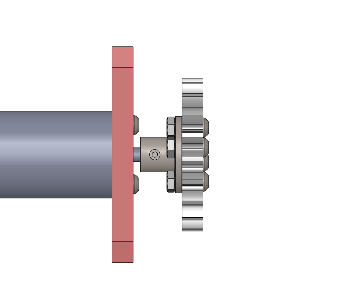
Gearmotor mounted to a panel with a laser-cuttable spur gear attached using a flange hub. This version requires M3 nuts on the M3x10 button-head cap screws. This configuration places the hub on the inside.
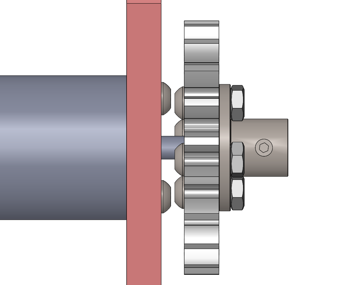
Gearmotor mounted to a panel with a laser-cuttable spur gear attached using a flange hub. This version requires M3 nuts on the M3x10 button-head cap screws. This configuration places the hub on the outside. Note that the shaft does not fully reach the end of the hub bore.