CNC Arduino Shield
We will be using the Protoneer CNC Shield for the exercises and projects in the course utilizing stepper motors. This board attaches to an Arduino Uno and carries three Pololu A4988 stepper motor drivers.
Contents
Arduino Installation
The CNC Shield should be installed on an Arduino Uno as shown in the following image:
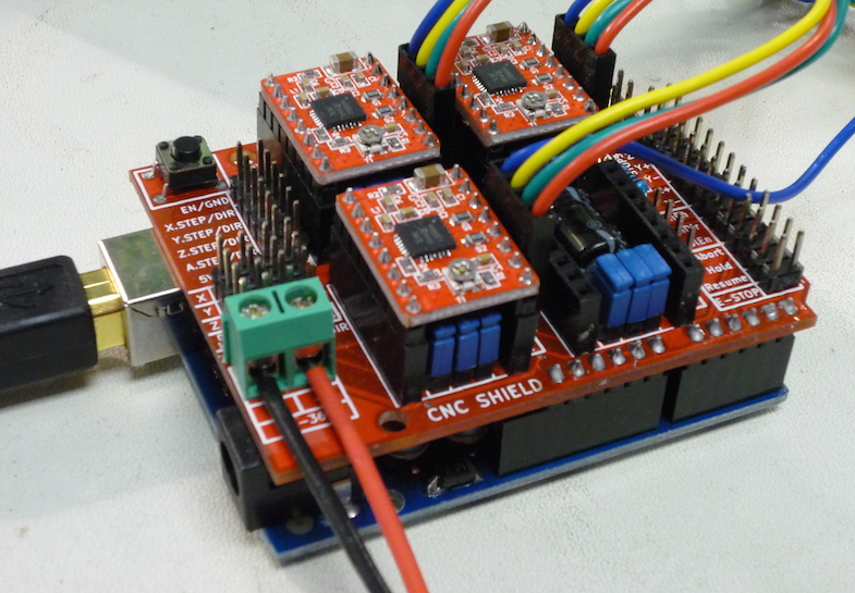
CNC Shield board installed on top of an Arduino Uno.
Note that the shield board has four fewer pins than socket positions on the Arduino; be sure that A4, A5, D0, and D1 are connected and the board outlines line up.
Driver Installation
The drivers should be installed in the locations and orientations as shown in the following image:
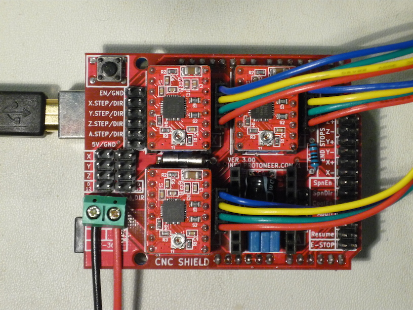
Top view of CNC Shield showing USB cable, power leads, A4988 drivers, and motor leads.
Please carefully note the polarity of the motor supply wiring at the lower left of the image; these should be connected to a 12V power supply. Please be extra careful not to attach a 12V supply to the 5V Mini Maestro which we also use.
The colored wires to the right are the stepper motor leads for the KL17H248-15-4A. Either connector orientation works, although this particular orientation is recommended for consistency, with blue toward the top.
Note that each driver has a potentiometer adjustment for the current limit; this must be set as described below.
Current Limiting
The A4988 actively limits the current flowing through each stepper motor coil according to the setting of the current limit potentiometer and the active microstepping phase. This allows a supply voltage substantially higher than the rated motor voltage, increasing step rate performance.
The current limit must be set correctly for the particular motor installed on the driver. It is most easily configured by measuring the voltage on the wiper of each reference potentiometer while using a tiny screwdriver to adjust it. The wiper pin is in the center of the edge located toward the inside of the board. The 5V logic power must applied to the CNC shield, normally by making sure the Arduino is powered via USB. The correct reference voltage is as follows:
VREF = I_max / 2.5
For example, the preferred KL17H248-15-4A NEMA17 stepper motor has a rated
current of 1.5 A, so the correct VREF = 1.5A / 2.5 = 0.6V.
NEMA17 Stepper Motor
We are using the KL17H248-15-4A NEMA17 stepper motor with the CNC Shield. This is a bipolar 200 counts/rev 1.5A/phase stepper motor in a square NEMA17 package. The shaft is 5 mm diameter with a flat, the mounting screws are M3 located on a 31 mm square.
Drawing: cnc-images/KL17H248-15-4A.pdf
Arduino Pin Assignments
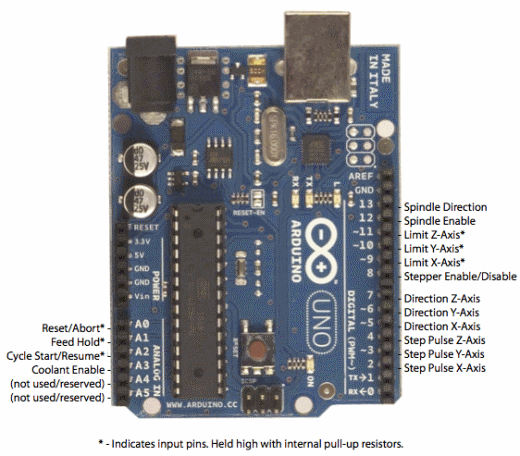
Top view of Arduino with pin definitions labeled.
CNC Shield Circuit Diagram
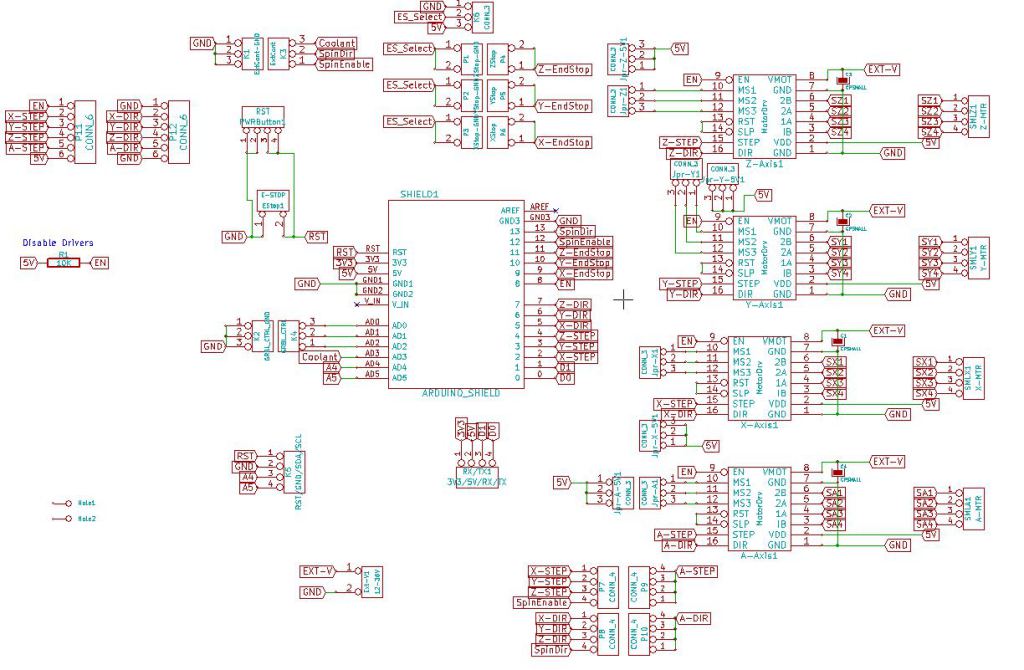
Electronic schematic of CNC Shield board.
CNC Shield Component Layout
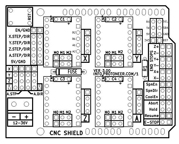
Top silkscreen of CNC Shield board.
Microstepping Setup
The A4988 is capable of microstepping at 2X, 4X, 8X, or 16X the full-step resolution, configured using pull-up jumpers located beneath each driver module on the CNC Shield board; please refer to the positions labeled M0, M1, or M2, in the image above.
With no jumpers installed each step pulse is a full motor step; with all three each step pulse is 1/16 of a motor step, trading off speed for accuracy. The full configurations are as follows:
M0 |
M1 |
M2 |
Microstep Resolution |
|---|---|---|---|
No |
No |
No |
Full step |
Yes |
No |
No |
Half step |
No |
Yes |
No |
Quarter step |
Yes |
Yes |
No |
Eighth step |
Yes |
Yes |
Yes |
Sixteenth step |
Anecdotally, using our NEMA17 stepper motors unloaded but without any acceleration control, the maximum speed at full step is around 4 rev/second (800 steps/second). At 4X microstepping, this appears to improve slightly to around 5 rev/sec (4000 steps/sec), and the noise is reduced. This can be further improved by limiting the acceleration so the velocity profile ramps up, allowing the motor inertia to keep up with the changing magnetic fields.
Fourth Axis Setup
The shield supports a fourth “A Axis” driver which may be configured using jumpers to mirror any of X, Y, or Z, or it may operate independently. In independent operation it uses D12 for A-STEP and D13 for A-DIR, precluding use of these pins as SpinDir or SpinEnable.
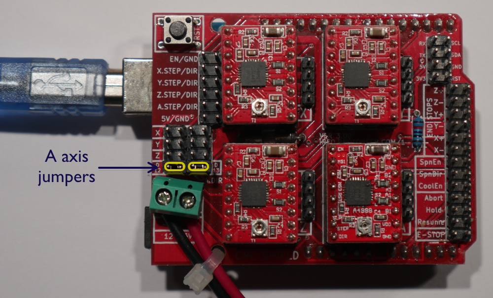
Configuration for four independent axes. Jumpers are installed at the two positions marked in yellow. The fourth driver is installed in the lower right socket.