Servo-Driven Syringe Pump
The heat-sealed pneumatic actuators can be manually actuated using the 20 mL syringes. We have also provided laser-cut parts to construct a mounting that connects two LKY62 hobby servos to drive the syringes. Please note that this is an experimental resource and the design is still a work in progress. We ask for your patience while we refine the design together.
Contents
CAD Renderings
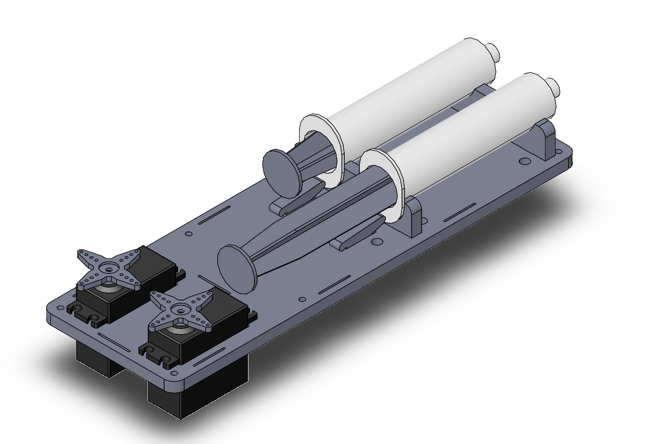
CAD isometric view of a servo-driven pump using a pair of 20 mL syringes. Not shown: linkage rod, retaining wire ties.
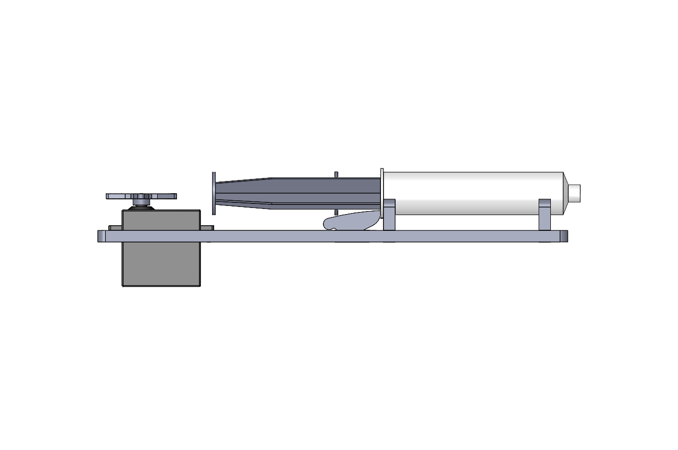
CAD side view of servo-driven syringe pump. Not shown: linkage rod, retaining wire ties.
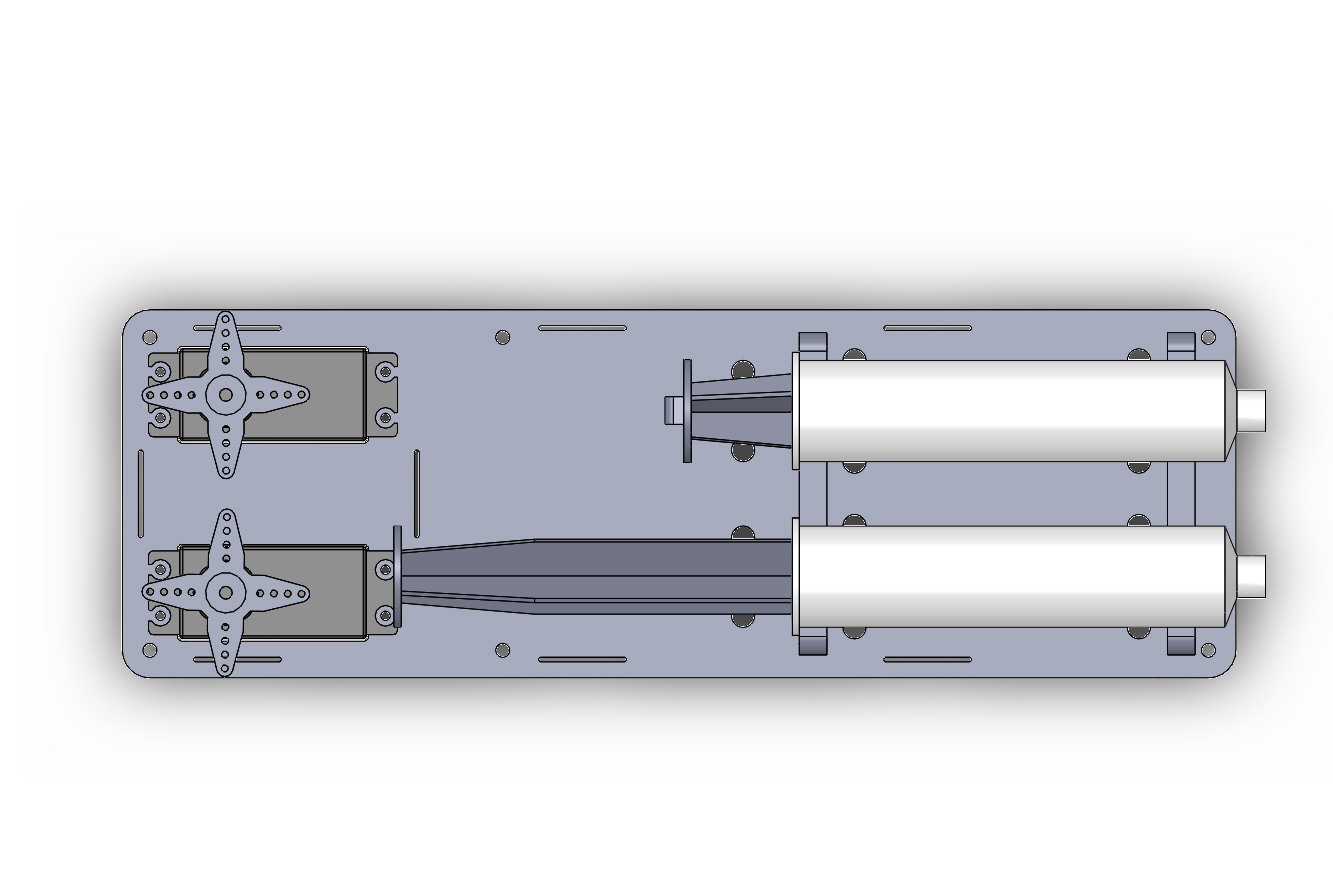
CAD top view of servo-driven syringe pump. Not shown: linkage rod, retaining wire ties.
Assembly Photos
The following photos show a pump with one motor and syringe assembled.
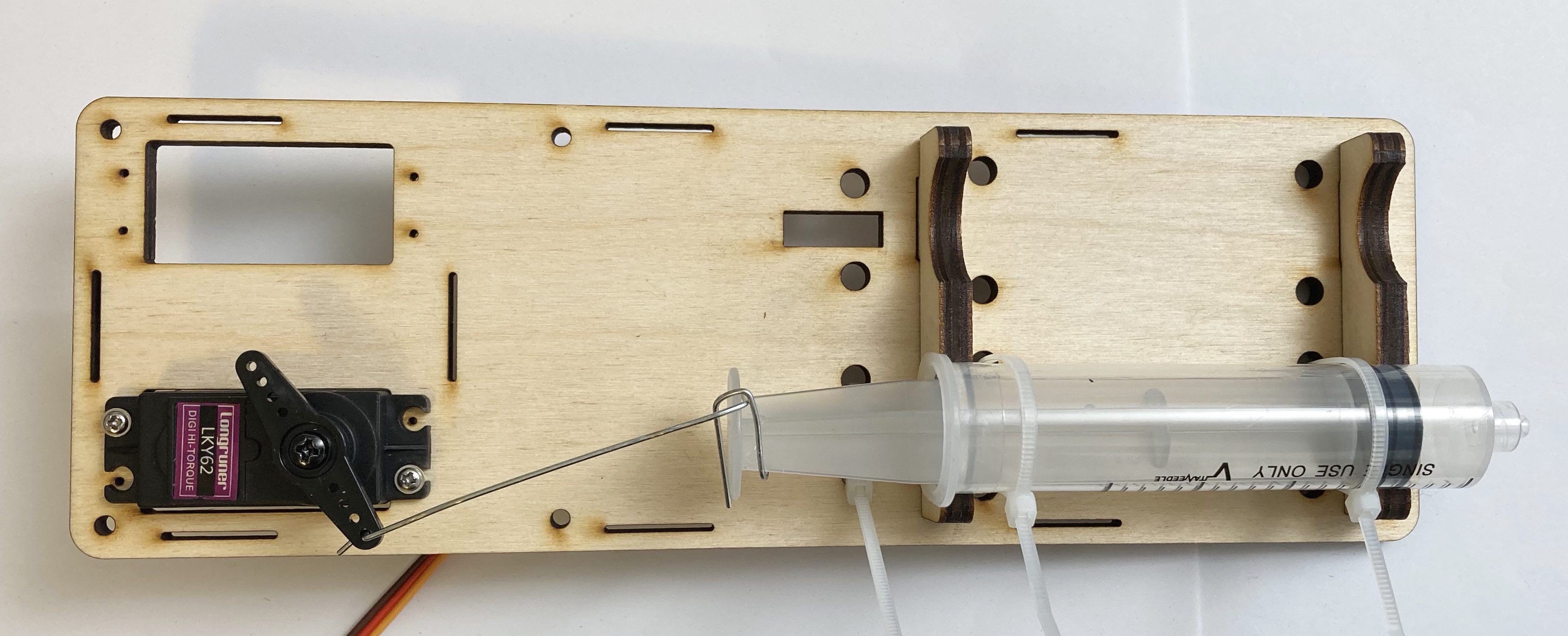
Photo of top view of a servo-driven syringe pump with one half assembled.
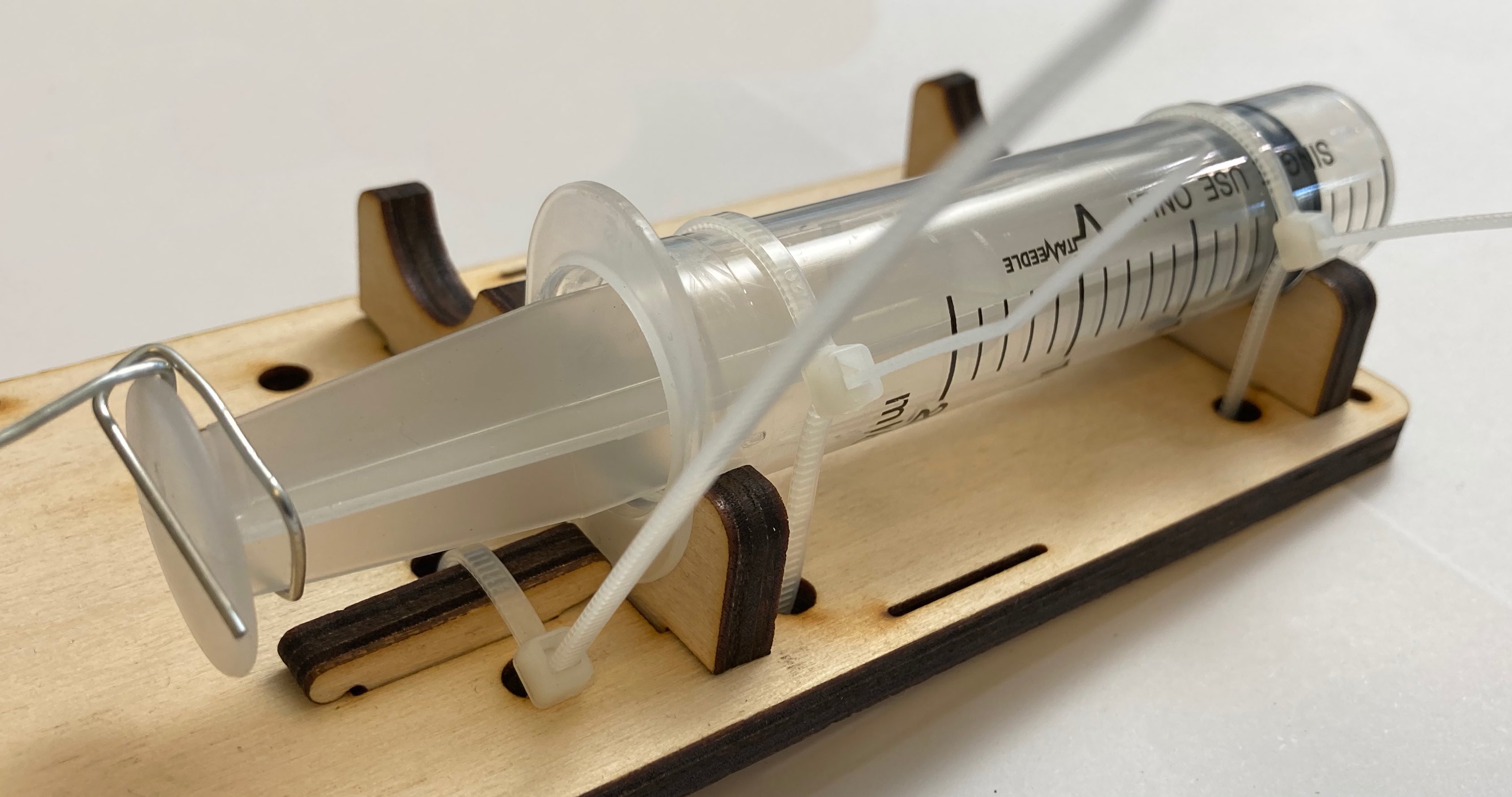
Photo of details of the syringe mounting.
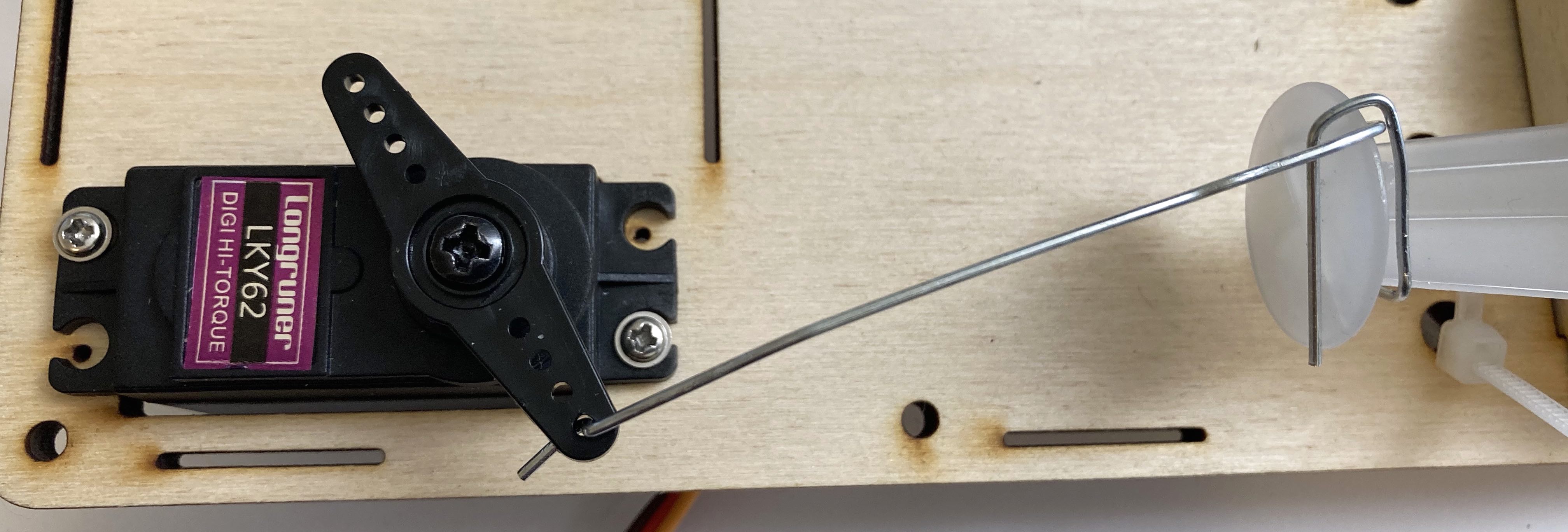
Photo of details of the linkage rod made from a jumbo paper clip.
Required Assembly Tools
Small Philips screwdriver.
Small pliers suitable for bending paper clips.
Optional: wire cutters to trim wire ties.
Assembly Parts List
The parts list for assembling the first half (one actuator):
Qty |
Description |
|---|---|
1 |
laser-cut base plate |
2 |
laser-cut pillow blocks |
1 |
laser-cut locking key (out of two) |
1 |
20 mL syringe |
3 |
small wire ties |
1 |
LKY62 servo and some of the included hardware |
1 |
LKY62 straight servo horn (included with LKY62) |
2 |
LKY62 mounting screws (included with LKY62) |
1 |
LKY62 horn retaining screw included with LKY62) |
1 |
jumbo paper clip |
The parts list for adding the second actuator omits the base plate and pillow blocks, but is otherwise the same.
Assembly Sequence
Installing the first syringe.
Insert the two laser-cut pillow blocks into the base plate.
Temporarily remove the plunger from a syringe.
Locate two small wire ties and set them within reach.
Set the syringe on top of the pillow blocks with the flange butted against the servo-side face of the interior one, and the long axis of the flange vertical.
Thread a wire tie through the base plate holes around the syringe body and lightly secure it
Install the second wire tie around the syringe body.
Install the laser-cut locking key in the slot. It should press gently against the lower lip of the syringe flange.
Wire-tie the locking key in place with a third wire-tie.
Re-install the plunger.
Installing the first servo.
Locate the LKY62 servo package and remove the following items:
hobby servo
straight plastic horn (two arms)
two mounting screws (sharp wood screws)
one servo retaining screw (black machine screw)
Insert the servo into the base plate from the top, orienting the output spline on the syringe end.
Install the two mounting screws, one through each servo tab into the pilot holes in the wood. (You may also choose to install all four.)
Temporarily install the plastic horn on the servo output spline.
Manually backdrive the servo to find the travel limits, then position it in the center of travel.
Remove the servo horn if needed and reinstall it perpendicular to the servo body in the center-travel position.
Install the horn retaining screw.
Manually rotate the servo horn to move the outside tip toward the syringe close and align with the servo body.
Making the first linkage rod.
Locate the jumbo paper clips.
Use pliers to straighten a clip.
Bend a short L into one end to fit into the servo horn.
Add a second bend at a distance to wrap around the neck of the plunger.
Fit the linkage rod into the servo horn.
Continue adding bends to wrap fully around the plunger neck, then back around to the outside face of the plunger end.