DC Motor Pump Guide
One option for creating self-contained or wearable pneumatic systems is to use small pumps driven by battery-powered DC motors to inflate and deflate small pneumatic actuators. The fill rates are relatively slow, but the total volume is only bounded by time.
Following are notes on the pump mechanical and circuit considerations. For sample code, please see Motor Pump Examples - Adafruit Circuit Playground Bluefruit.
Adafruit 2.5 LPM Pump
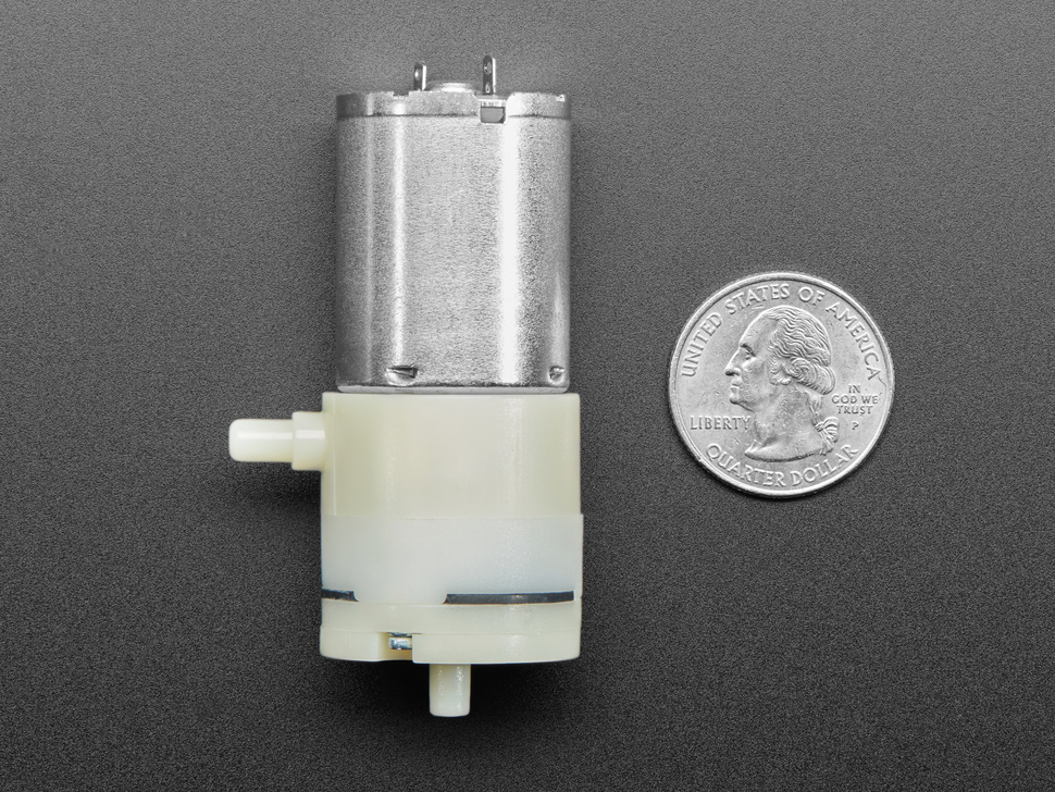
Adafruit 2.5 LPM air and vacuum pump. The side port is the air intake, the axial port is the air output.
One option for operating wearable inflatables is the Adafruit 2.5 LPM Air Pump.
We tested the motor using a four-cell NiMH battery pack measured at 5.1V and observed a motor current draw of 350 mA with no load, climbing to 500 mA with the output capped (max load). This magnitude of current requires a motor driver circuit to control the motor from a microcontroller. Pulse-width modulation at 20 kHz was effective at controlling motor speed over a range from 100% to around 75% duty cycle, at which point the motor stalled.
The output port is a cylindrical tube extending axially from the end. The input port on the side includes a cylindrical base which is wider than the tube extending from it.
The motor leads are copper tabs extending from the base. We recommend soldering permanent wires to these tabs and using tape or a wire tie to secure the wires to the motor body to relieve strain on these tabs. Otherwise these types of tabs tend to break off from the repeated strain of alligator clips or long unconstrained wires.
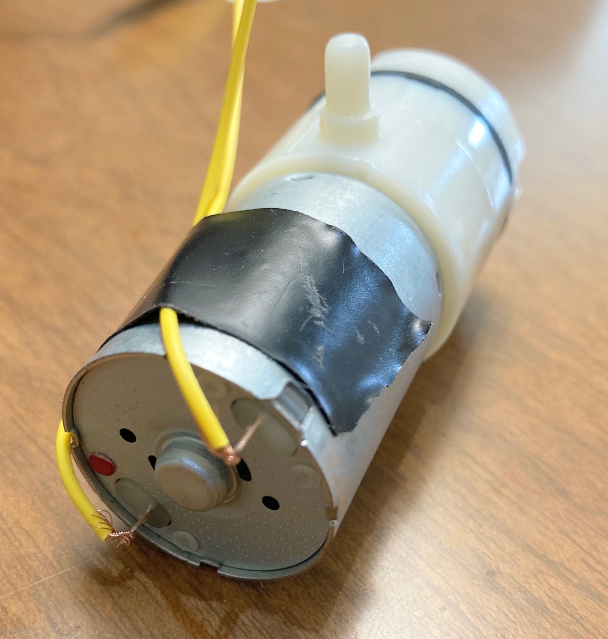
Suggested solderless preparation of wire leads. The two yellow jumper wires have had one terminal cut off and the ends stripped. The wires are threaded through the eyelets of the motor tabs and twisted tight. Note the strain relief tape holding the wires to the motor body, they can help prevent the tabs from breaking off. Ideally, the wires would also be soldered to the tabs.
Dimension |
Value |
|---|---|
output port external diameter |
4.3 mm |
output port length |
5.6 mm |
input port external diameter |
4.3 mm |
input port length |
6.5 mm |
input port base diameter |
5.8 mm |
input port base length |
2.7 mm |
Motor Driver Board: Crickit
The easiest way to connect the motor pump to a Circuit Playground Bluefruit is to use the motor and solenoid drivers on a Crickit. Please consult Adafruit Crickit for Circuit Playground Bluefruit.
Motor Driver Circuit: MOSFET
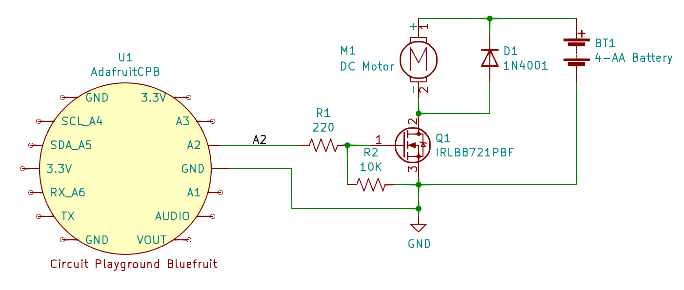
Sample application circuit for driving a motor from the Circuit Playground Bluefruit using a MOSFET power transistor. The example uses PWM output from pin A2, but any other digital output can also work. The resistors R1 and R2 and the external diode D1 are recommended practice, but for a motor as small as this pump may be omitted by leaving out R2 and D1 and wiring A2 directly to the Q1 pin 1 gate terminal.
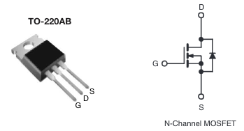
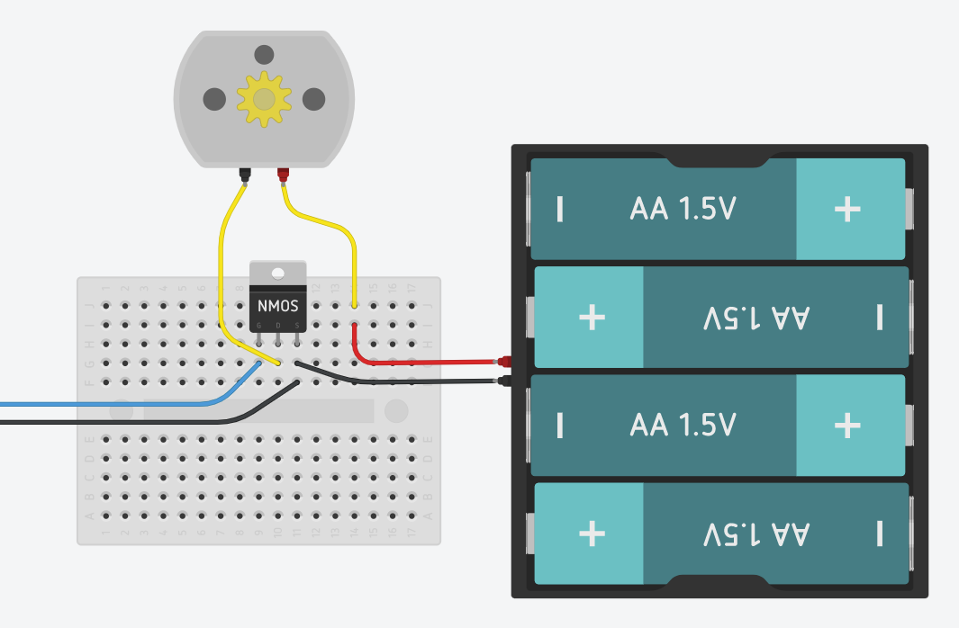
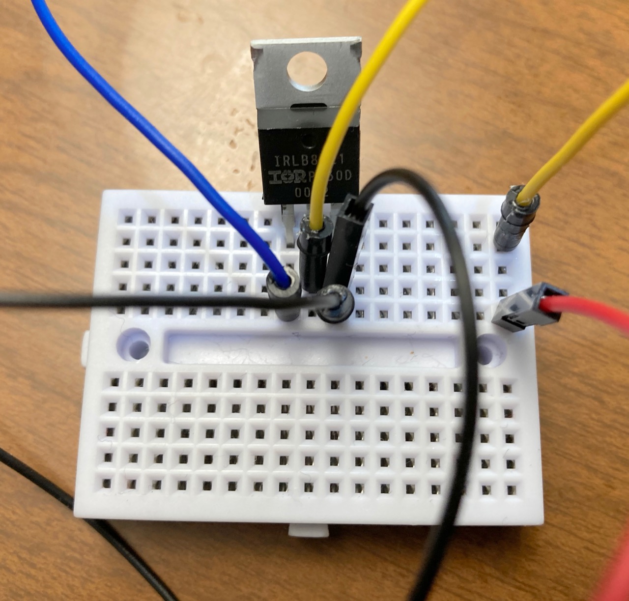
The left image shows a MOSFET power transistor in a TO-220 package. Please note the pin layout: as viewed, the gate input is on the left, the positive drain terminal is in the center, and the negative source terminal is on the right.
The center image shows a sample breadboard implementation of the MOSFET driver. The recommended resistors and diode are omitted. The blue wire carries the PWM signal from the microcontroller to the left ‘gate’ terminal. The yellow motor wires connect between the center ‘drain’ terminal and the red battery lead. The black wires from the microcontroller and battery connect to the right ‘source’ terminal.
The right image shows a sample physical breadboard implementation.
Motor Driver Module: DRV8833
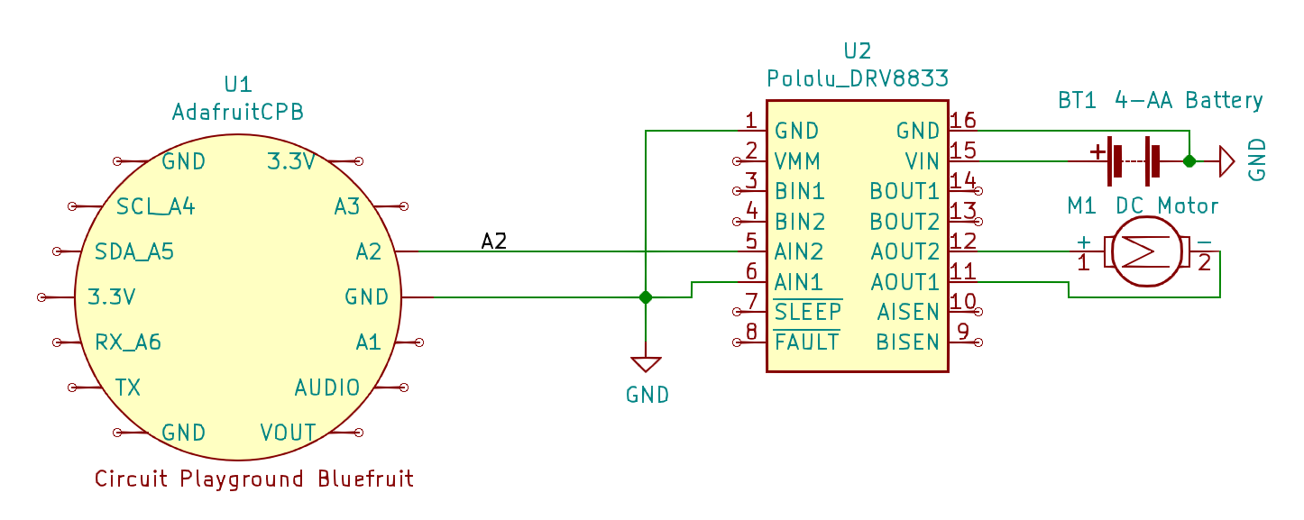
Sample application circuit attaching the DRV8833 dual motor driver module to a Circuit Playground Bluefruit. Please note that the battery voltage is higher than the Bluefruit can tolerate, so please pay attention to the wire routing into VIN. This circuit uses only a single pin to control speed for the pump; more general DC motor applications use two pins to control speed and direction. The example uses PWM output from pin A2, but any other digital output can also work.
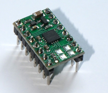
DRV8833 dual motor driver packaged in a Pololu module.