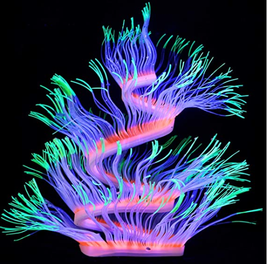
We present a playful design system that embeds actuation and computation in ordinary materials like paper. Our technique turns two-dimensional paper structures into self-morphing plants that react to the stimulus of water and transform themselves into organic, pre-programmed ways when placed within underwater environments.
MORPHING PRIMITIVES
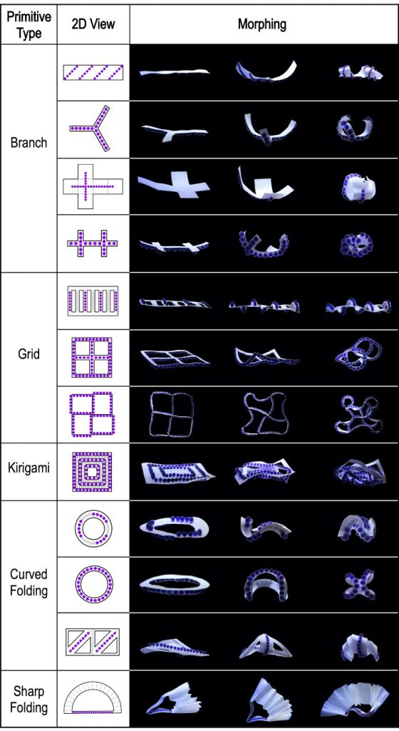
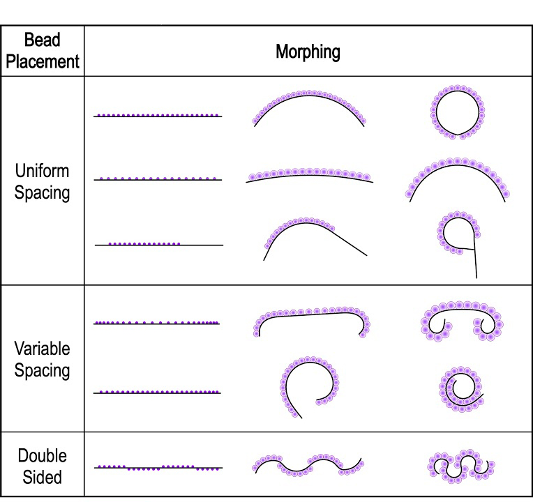
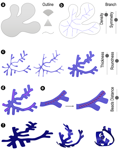
We explored a rich vocabulary of morphing primitives based on the structure and mechanism of Hydrogel Beads On Substrates as shown in Table 1. We hope this serves as a geometrical reference for readers who would like to create morphing structures with the proposed mechanism. The substrates can be divided into 1D linear structures and 2D sheets. For each substrate, the controllable parameters for the bead patterns include bead alignment direction and the gap distance between beads. We were inspired by the primitive designs presented in Printed Paper Actuators [36], and demonstrated that our beads on substrates can reach a similar level of shape complexity without the need of 4D printing and shape memory filament. Later we will show how the morphing primitives can be combined to form more complex and hierarchical morphing structures.
COMPUTATIONAL DESIGN WORKFLOW
We developed several computational design tools and a simulation tool to guide users through a generative design process for the morphing mechanism of hydrogel beads on substrates. Users can generate a geometry, define the distribution of hydrogel beads, simulate the morphing behavior, and generate fabrication files through the tool. The tool currently supports two generative structures – branch and kirigami. Additionally, users can create their own geometries from scratch.
Simulation Model
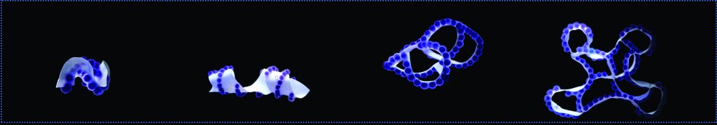
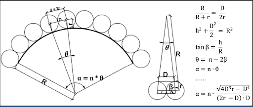
As hydrogel beads expand after deployed underwater, they eventually collide with each other. The expansion of the beads causes the bending of the substrate, and the maximum bending angle is determined by the distance (D) between adjacent beads and the radius (r) of each bead, as illustrated in Figure 1.
We further verified this bending-angle control mechanism with a numerical simulation model as can be seen in Table 2.
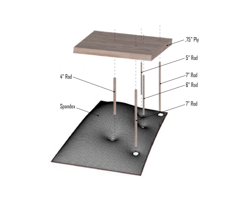
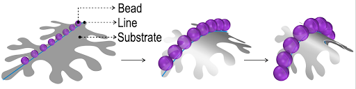
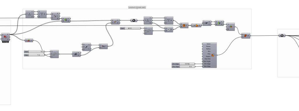
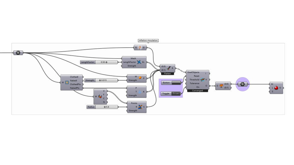
Since we only deal with the bending behavior that has one degree of freedom, we can simplify our bending model as beads on straight lines. More specifically, a line is represented as a polyline with segments divided by the beads. Each line is set to be free to bend or twist around its own axis. One anchor point (i.e. boundary condition) has to be set for each line in order to run the simulation correctly. To accommodate diverse substrate patterns in our simulation model while keeping the underlying simulation model simple and fast, we divide a given structure into three basic geometrical elements: bead, line, and substrate (Figure 2). A line with beads resides on top of a substrate and can be drawn and defined by users in our computational design tool interface. We first simulate the bending of the line based on the distribution of beads. A ‘circle packing method’ [33] is employed to define the moment of bead expansion and collision. The final simulation of the substrate is then achieved by mapping the original positions of points on the line to the final positions
USER DESIGN WORKFLOW
Currently, our design tool supports the generative design of branches and kirigami-based structures. For both structures, the workflow is similar, including both generative design and simulation. The user design flow for the computational design platform is composed of the following steps as shown in Figure 8.
Step 1: Specify an outline of the substrate. Users can select a basic outline from the library or draw a closed outline from scratch (Figure 3a).
Step 2: Generate branches that will fill the outline automatically (Figure 3b). Many geometrical features of the branches can be adjusted (Figure 3c), such as the total numbers of hierarchy, the smoothness of each corner, etc.
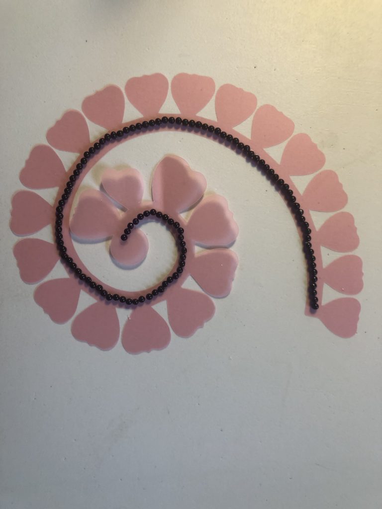
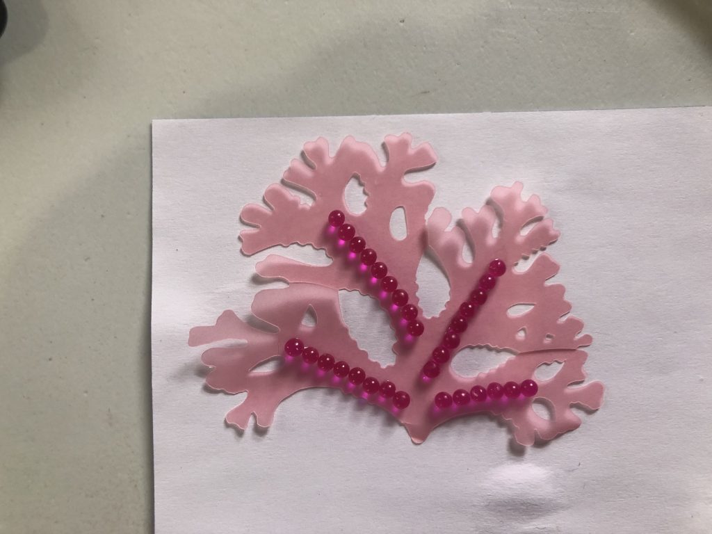
Step 3: Specify the layout of the beads. Users firstly draw polylines to indicate which branches to be actuated. Beads will be generated along the actuation lines (Figure 3d). Users can then adjust the distance between each adjacent bead, which will affect the maximum bending curvature of the corresponding line (Figure 3e). Users can also select the side of the substrate on which the selected beads will reside.
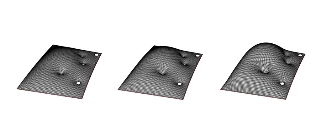
Step 4: Simulate the transformation i.e. the morphing behavior (Figure 3f). Step 1 to 4 can be iterated to reach a desired shape and transformation.
Step 5: Export the outline of the substrate for laser cutting and export a .pdf file as a reference for bead placement and adherence to the substrate.
Generative Geometries
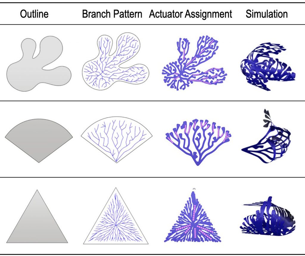
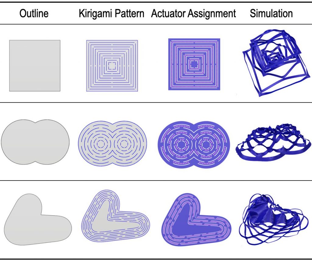
In the computational design platform, we provide two predefined generative shape libraries for users i.e. branching system and kirigami system; and both of them can automatically suggest layout paths for beads in their output.
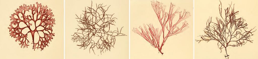
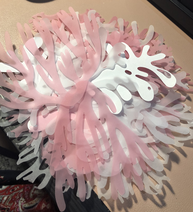
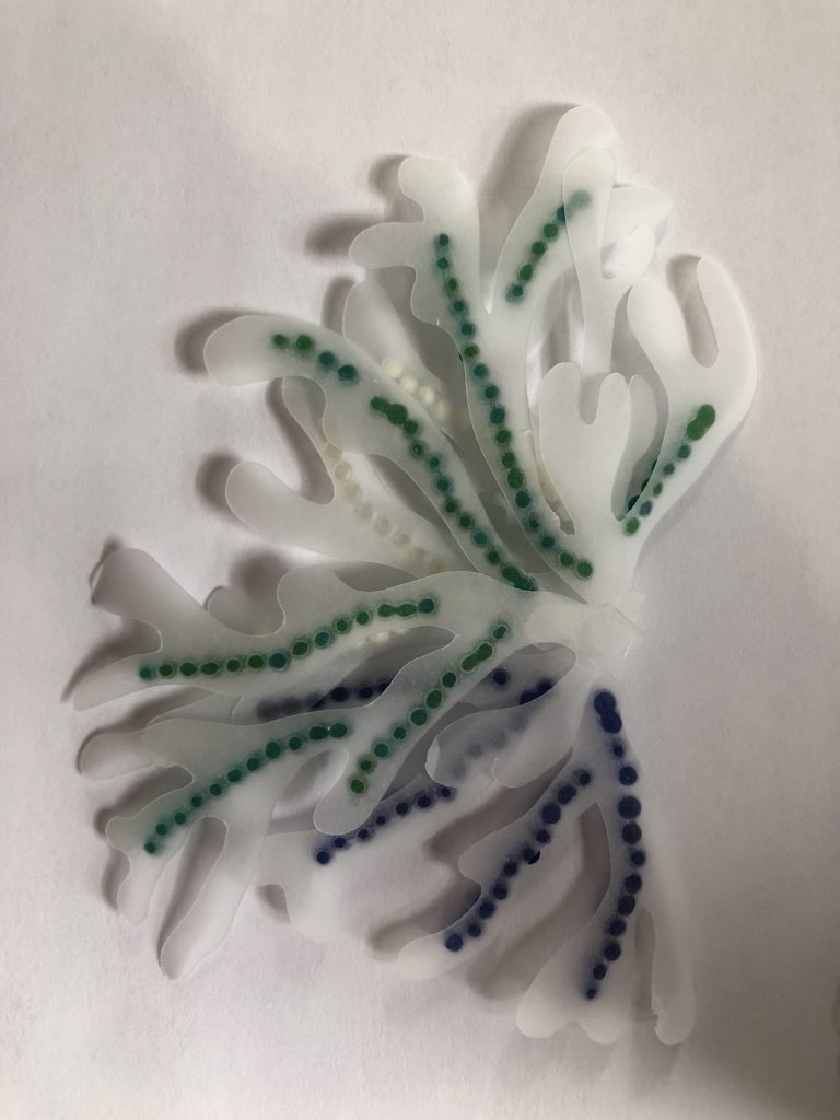
Branching System: Branch patterns are inspired by corals and seaweeds, following our design guideline of generating biomimetic and organic forms for an ocean garden. Figure 4 shows a collection of British seaweed archived in the 19th century [12].
We adopted the Diffusion-Limited Aggregation (DLA) method [43] to develop rule-based branching generative structures. It opens a design space of fractal growth-producing organic dendritic skeletons with biomimetic aesthetics. While these skeleton lines serve as potential bead layout paths, a non-uniform parametric thickening post-process results in an organic boundary curve with various radius values at different hierarchies of the branch structure. We added additional randomness in the geometry to mimic natural underwater living organisms.
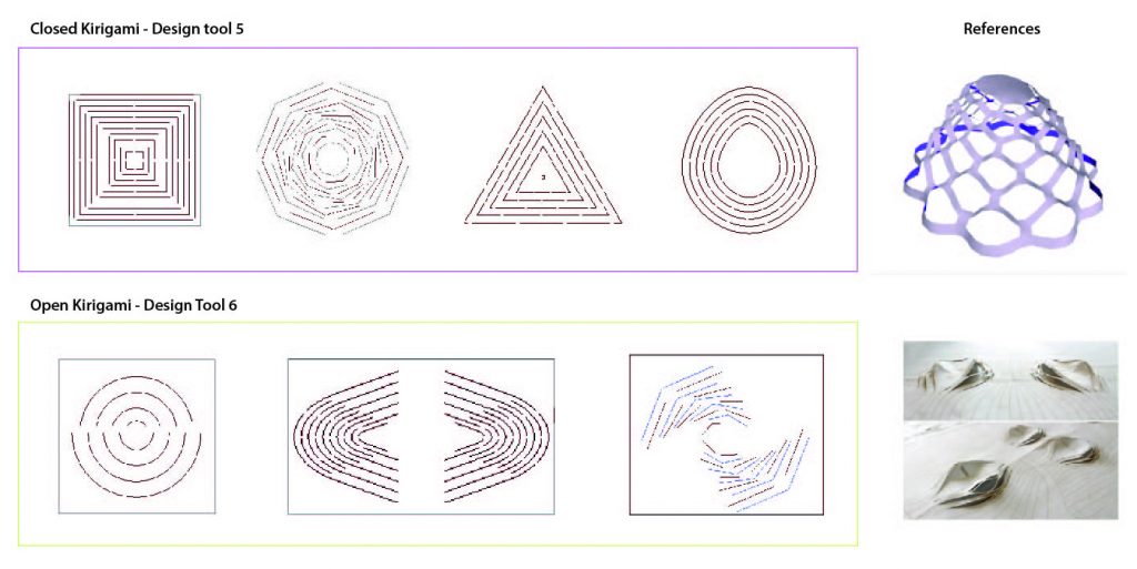
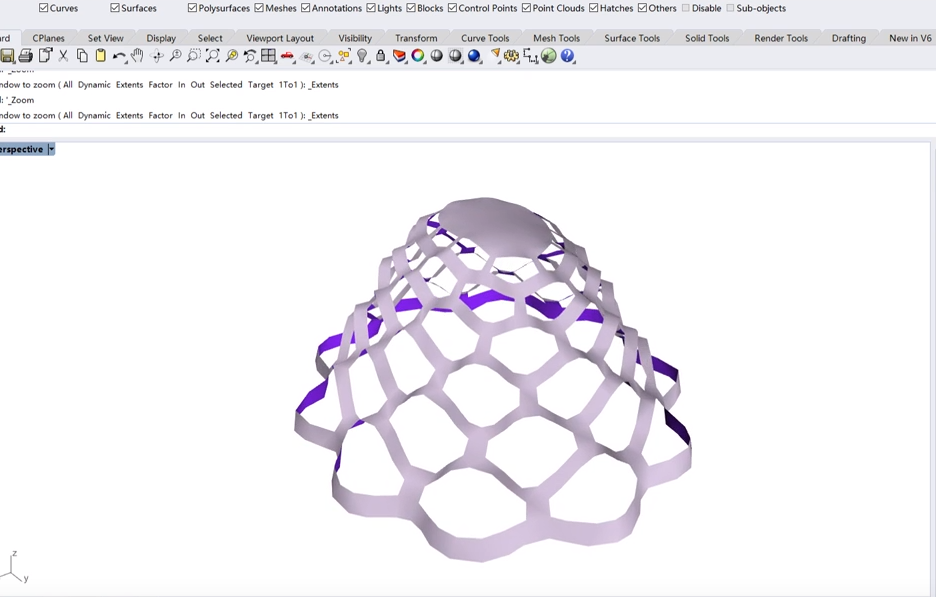
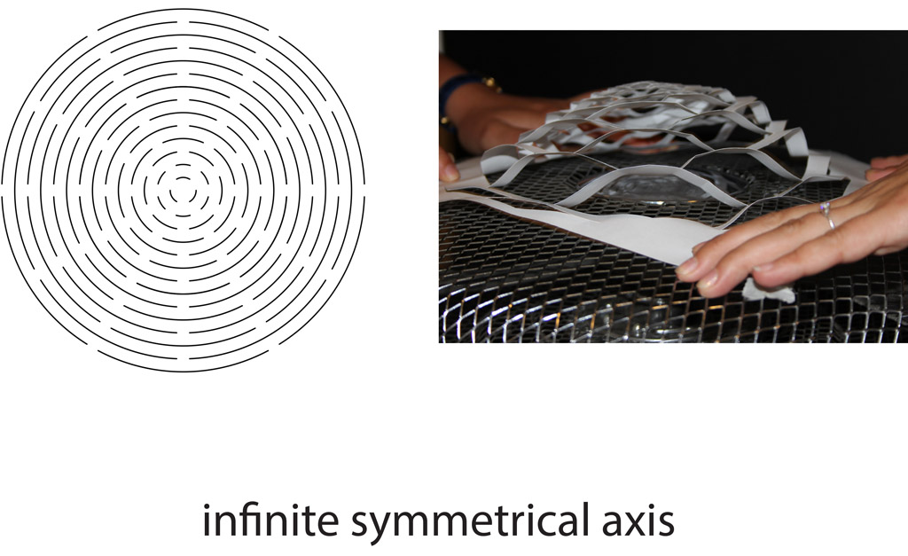
Kirigami System: Taking the basic input geometry as the outline, a variety of cutting patterns can be generated based on the variation of different parameters including the number of concentric cutting cycles, the number of cuts on each cycle, and the size of the gap between the cuts.
Fabrication Process
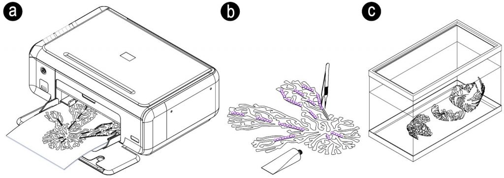
From the digital files generated through our design tool, we can cut the designed pattern and mark the location of the bead within one CNC plotter (Curio, Silhouette America) in two sequential steps (Figure 7a). The next step involved applying a very small quantity of cyanoacrylate glue to the paper or cloth substrate using a glue dispenser tip, just enough to hold a hydrogel ball. The hydrogel balls were placed with tweezers (Figure 7b). Applying a very small quantity of glue in a discrete manner at each contact spot was critical to maintaining the flexibility of the substrate. Otherwise, when the glue was applied in a continuous line, the substrate became hard and stiff, acting as an additional constraint, reducing the efficacy of the bending behavior. Lastly, for our deployment experiment, we used a water tank by simply dropping the structure into it (Figure 7c).

]]>
Kexin Lu, Twisha Raja, Maria Vlachostergiou
Methodology description:
In our project ‘underwater garden’, we present a playful design system that embeds actuation and computation in ordinary materials like paper. Our technique turns passive paper into a self-assembling / self-morphing composite that reacts to the stimulus of water and transforms itself in interesting, pre-programmed ways.
The two methods used are:
A) the kirigami technique as a design system for the exploration and production of three-dimensional form out of two-dimensional shapes and B) the idea of a new, programmable, bi-layer composite that uses hydrogel balls and paper as actuating and constraint layers correspondingly.
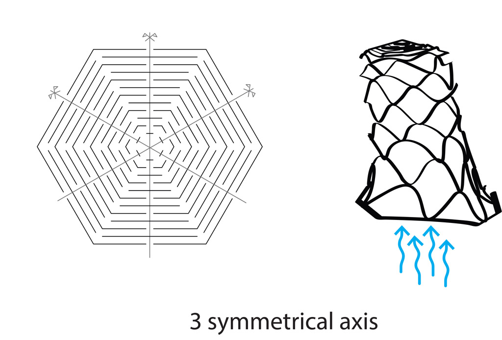
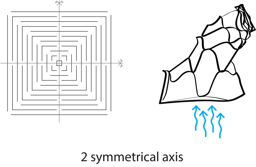
Method A: Kirigami
Example 1: An exploration of kirigami using anchors and offsets was carried out where the anchors denote the supporting portion of the paper whereas the cuts elevate 2D in space.
Example 2: Outlines of shapes that bend around a particular anchor point.
Method B: Programmable materials
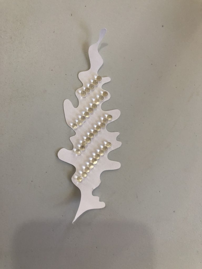
The idea here is to attach hydrogel balls to paper geometries, placing them in sequences that form different shapes upon those 2D geometries. Creating different shapes and orders out of hydrogels will cause the same paper kirigami to morph in different ways in space. The mechanics behind this concept is that hydrogel swells when absorbing water. On these grounds, the attached bubbles will force the paper to bend, as the paper will try to constrain hydrogel’s expansion.
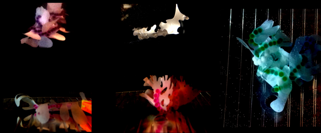
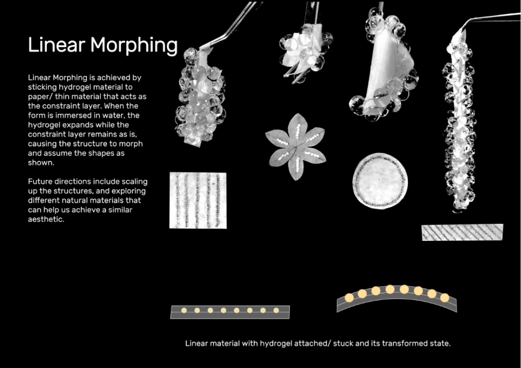
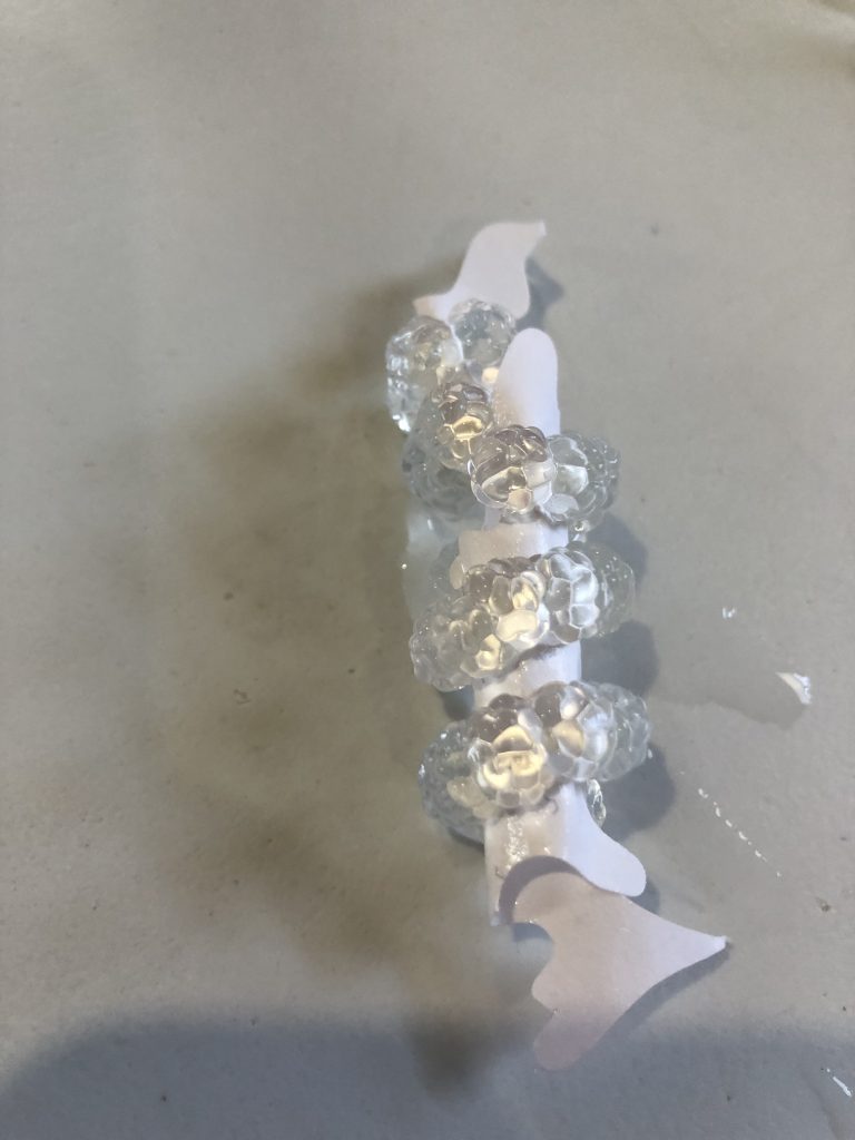
This methodology presents a bi-level actuation system where linear morphing is achieved by sticking hydrogel material to paper/ thin material that acts as the constraint layer. As the artifact is immersed in water, the hydrogel expands and the constraint layer remains as is. The second level of actuation is when the balls swell up which causes the structure to morph and take shapes as shown. Future directions include scaling up the structures and exploring different natural materials that can help us achieve a similar aesthetic.
Context and application:
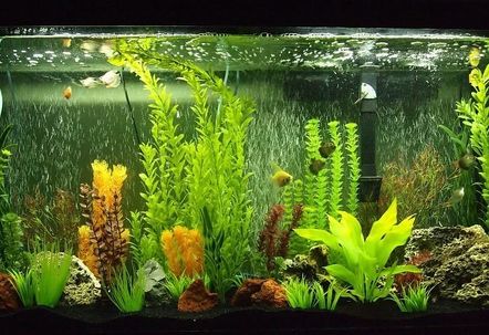
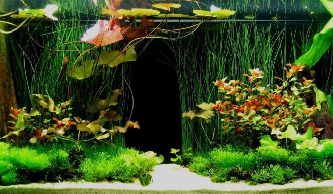
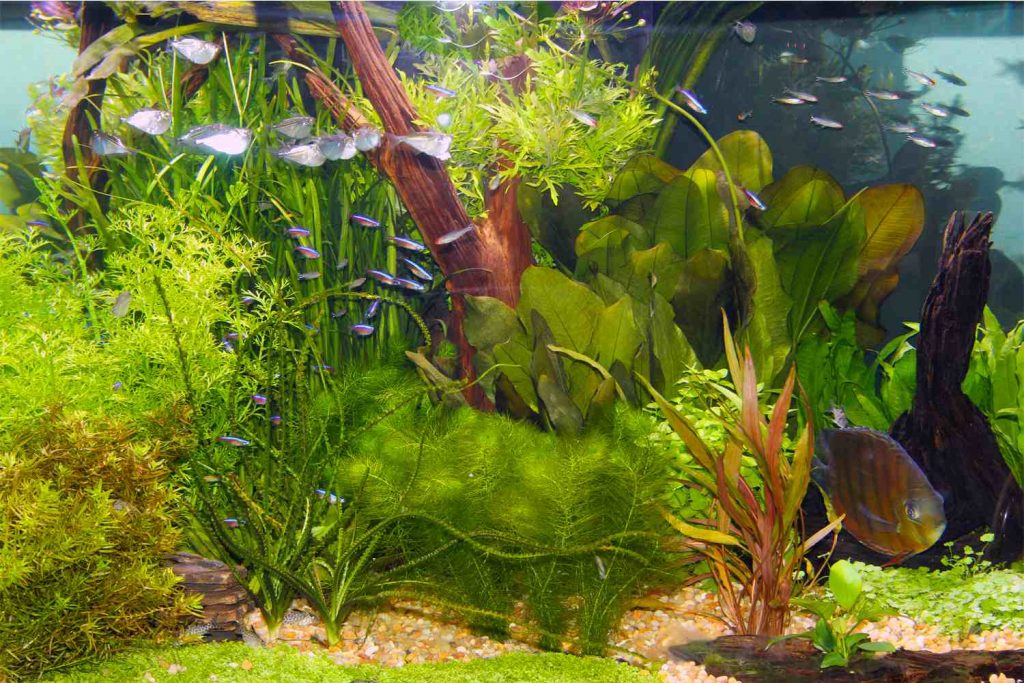
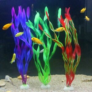

As we talk about a hydro-composite that uses water and humidity as environmental stimuli, we embrace and integrate the idea of an underwater environment for the context of our application. What if we used our two-core system to explore and build artificial structures of decorative plants for a fish tank environment? What if we created a series of available computational tools so that everybody could create their own decorations for their fish pets at home? That led us to the following inquiry: What kind of DIY tools should we create and suggest for use?

Tools to explore:
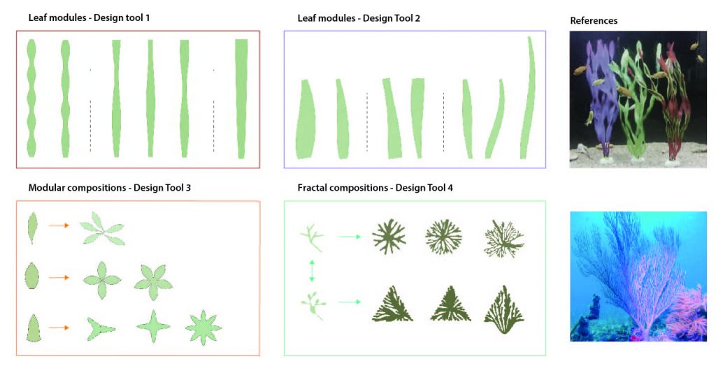
Tool 1: The first computational tool would be a series of generative design systems for the exploration of parametric, organic forms. Each of us will develop a different design system, exploring different ways of creating 3D structures out of 2D shapes. → Week 1
Tool 2: The second computational tool would be an interactive simulation system, in which we can apply the hydrogel effect in different shapes and make predictions about the ways various designs would morph underwater. → Week 2
Tool 3: Finally, the third tool would constitute a series of online videos, which will demonstrate how people could use the tools to produce designs, simulate the transformations and fabricate their own decorative plants ordering simple means like paper, super glue and hydrogel bubbles from Amazon.
Computational Design Process
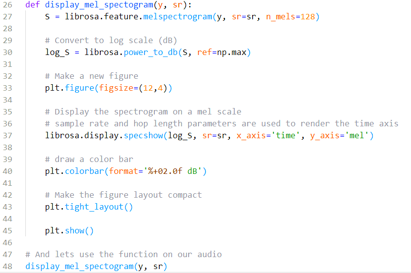
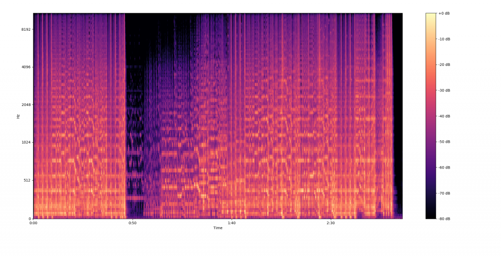
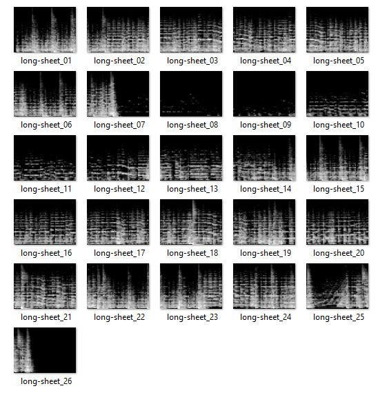
- Data Visualization
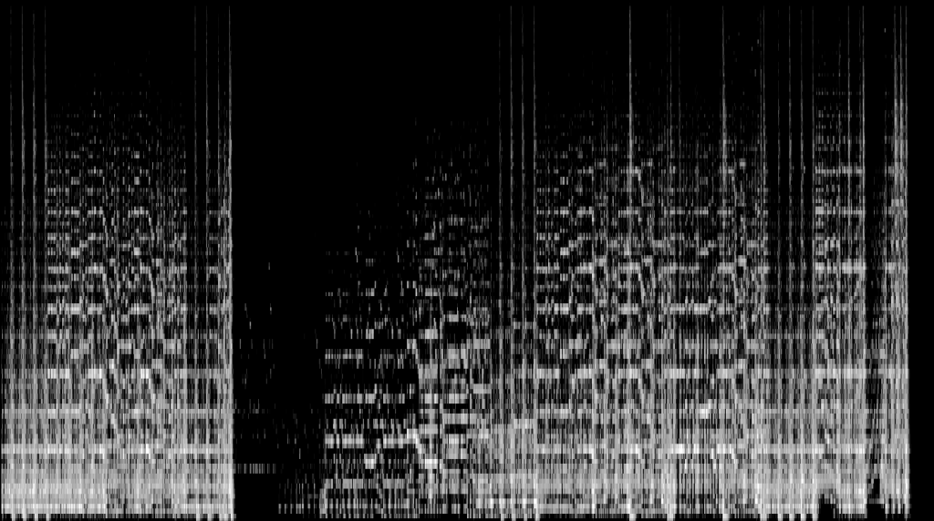
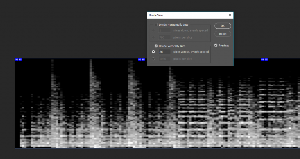
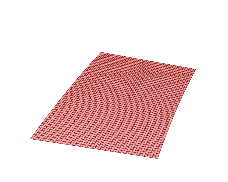
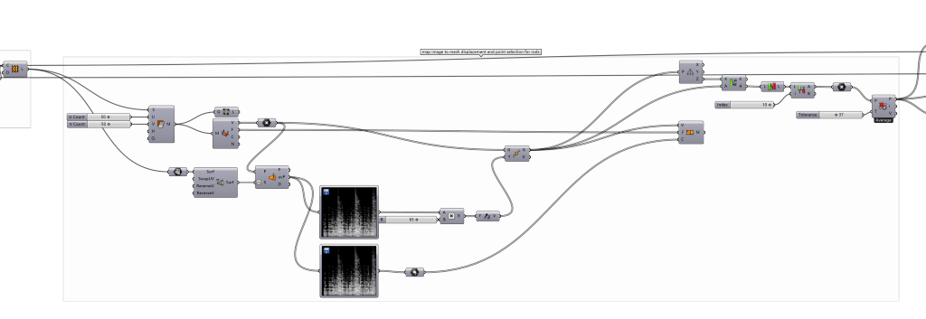
- Image Transformation
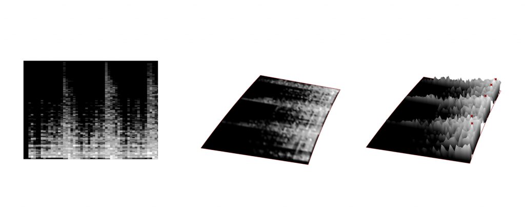
- Physical Simulation
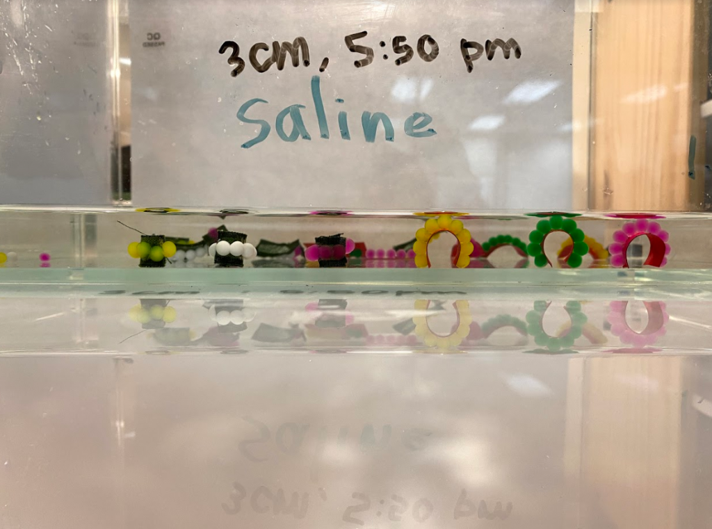
Physical Experiments