Design Example: Open Molded Soft Silicone Flexure
This example presents a silicone flexure designed to be fabricated using an open mold. The mold is designed for 3D printing, with tendon pathway features formed using wire rods and a dowel.
The SolidWorks model files and STL 3D printing fabrication files may be found in the SolidWorks/flexure-test-1 folder, or may be downloaded as a single file as flexure-test-1.zip.
SolidWorks Flexure Design Workflow
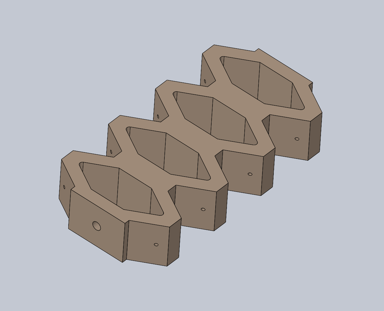
The part was modeled as a prismatic shape. The top face is flat as it will be formed by the open top of the mold.
The tendon paths and screw anchor hole will be formed by wire rods and a dowel pin inserted during casting.
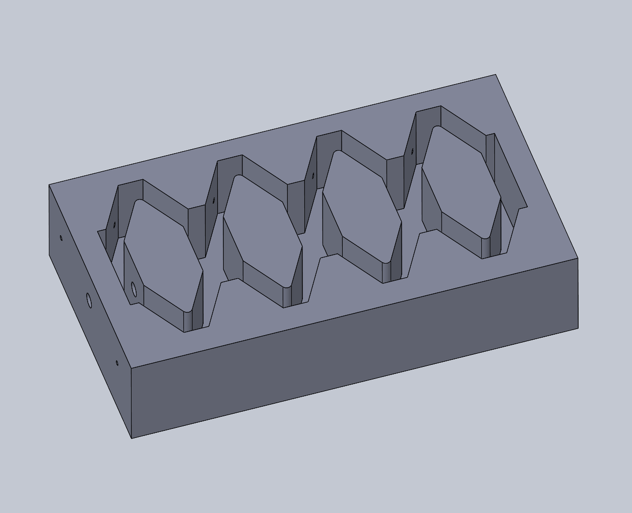
To generate the mold form:
The mold blank was modeled as a block larger than the part to fabricate.
As assembly was created using the mold blank.
The fabricated part was added to the assembly with mates to locate it inside the mold part. The top surface of the flexure part is coincident with the top surface of the mold block.
The wire rods and dowel pin parts were added to the assembly and aligned with mates.
The mold part was edited within the assembly context and a Cavity feature added to subtract the flexure part, wire rods, and dowel pin from the mold blank.
The mold part was exported as a STL file in millimeter units for fabrication.
Please note that the design is associative: changes to part geometry will propagate to the mold cavity when the mold assembly file is reloaded and rebuilt, and a new mold STL file may then be exported.
Assembly View
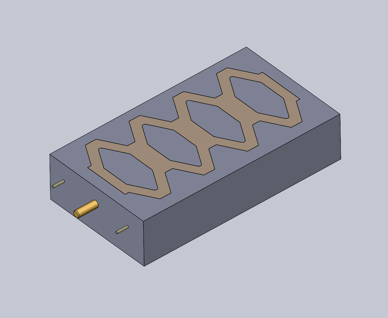
Rendering of the assembly with all components, used to define the cavity in the mold block.