https://kokecacao.me/page/Post/Writing_Minecraft_Shader.md
Writing Minecraft Shader

What is Shader?
Use Case
// TODO: case study
Terminology
Shader, roughly speaking are functions that transform geometry to pixel on screen. There are many things people called shader. For example, in Unity, shader is defined:
.shader file
properties: customizable user input (texture, normal, …)hidden properties: transformation matrix, meshshader: a combination of shaders for different platformsubshader #1: high quality render use this.vsh.fsh- …
subshader #2: low quality render use this- …
This part is inspired by Freya Holmér’s Video.
For consistency, when the word shader is mentioned, we refer a combination of files (that we called shader programs) that looks like .vsh and .fsh.
General Shader Pipeline with Vertex and Fragment Shader
data = vertices_of_geometry_in_world
data = data.map(vsh)
data = rasterization(data)
data = data.map(fsh) # actually this is in the process of rasterization as depth test is after fsh
pixels = antialiasing(data)

# This is a vertex buffer file written in python style pseudo code
def vsh(aPos, aNormal, aColor, aUVCoord, ... you define):
  # THIS IS WHAT WE CALLED `VBUFFER`
  # layout (location = 0) in vec3 aPos;
  # layout (location = 1) in vec3 aNormal;
  # layout (location = 2) in vec3 aColor;

  # THIS IS TRANSFORMATION MATRIX
  # uniform mat4 model;
  # uniform mat4 view;
  # uniform mat4 proj;
  global model
  global view
  global proj

  # DO MATH HERE: move vertex position, add attributes to vertex

  # out vec3 crntPos;
  # out vec3 normal;
  # out vec3 color;
  # Notice [gl_Position] here is not specified. We must use this name to tell OpenGL that this is the vertex position, not attributes we defined
  # crntPos is passed for light calculation
  return gl_Position, crntPos, normal, color, ... you define

def rasterization(all_vertice):
  # magic interpolation of all other attributes based on [all_vertice[gl_Position]]
  return fragments_and_interpolated_attributes_from_vertices

def fsh(crntPos, normal, color):
  # NOTE THAT THESE INPUTS ARE INTERPOLATED VERSION OF OUTPUTS FROM VERTEX SHADER
  # in vec3 crntPos;
  # in vec3 normal;
  # in vec3 color;

  # uniform vec4 lightColor;
  # uniform vec3 lightPos;
  # uniform vec3 cameraPos;
  global lightColor; # assuming there is one light
  global lightPos; # assuming there is one light
  global cameraPos;

  # DO MATH HERE: light, shadow, special effect

  # out vec4 FragColor;
  return FragColor
The concept of fragment is nearly identical to pixel, except multiple fragments can contribute to one pixel. This is so that we can implement multisampling or antialiasing. If no multisampling nor antialiasing, then there is 1-to-1 correspondence between fragment and pixel on screen.
Shader Pipeline with Vertex, Geometry, and Fragment Shader
The idea is basically the same except we add a geometry shader between vertex and fragment shader.
data = vertices_of_geometry_in_world
data = data.map(vsh)
data = assemble_to_triangles(data) # returns a list of triangles, lines, or points
data = data.map(gsh)
data = rasterization(data)
data = data.map(fsh) # actually this is in the process of rasterization as depth test is after fsh
pixels = antialiasing(data)

def vsh(...):
  # Everything is the same except we do not do transform and projection any more. They are done in gsh now.
  pass;

def gsh(crntPos, normal, color):
  # layout (points) in;
  # layout (triangle_strip, max_vertices=8) out;
  setInputLayout(points); # Input can only be: points (one point), lines, triangles, lines_adjacency, triangles_adjacency
  setOutputLayout(triangle_strip, max_vertices=8); # Output can only be: points (multiple points), line_strip (multiple lines), triangle_strip (multiple triangles). We want to output vertices at maximum.


  # NOTE THAT THESE INPUTS ALL ARRAYS NOW CONTAINING 1, 2, OR 3 ELEMENTS
  # in vec3 crntPos[];
  # in vec3 normal[];
  # in vec3 color[];

  # some uniform

  # DO MATH HERE: remove triangle, add mesh to point, add more triangles near this triangle, add or remove attributes to vertex
  vec4 vertexPos = gl_in[0].gl_Position; # for example, get the position of first vertex

  # Now we create a rectangle consists of 4 vertice
  # Remember to transform and project those vertices
  gl_Position = vec4(...);
  EmitVertex();
  gl_Position = vec4(...);
  EmitVertex();
  gl_Position = vec4(...);
  EmitVertex();
  gl_Position = vec4(...);
  EmitVertex();
  EndPrimitives();

  # We also want to create a line
  gl_Position = vec4(...);
  EmitVertex();
  gl_Position = vec4(...);
  EmitVertex();
  EndPrimitives();

  # out vec3 cat;
  return cat

def fsh(cat):
  # in vec3 cat;
  pass
This section is inspired by ThinMatrix’s OpenGL Tutorial 49: Geometry Shader Introduction.
About Minecraft and Minecraft Rendering
Minecraft is a popular sandbox survival game and I have a long relationship with this game. Funny enough, my first line of code in a general purpose language environment is a
hello worldprinted in the Minecraft server console, and I have since then built a commercial Minecraft (with my costom GTA mode) server hosted about 300k players. To me and most of Minecraft enthusiasms, Minecraft is more than a game as it hosts communities of different interests: creative map makers, adventure map makers, minigame designers, traditional survival players, redstone technicians, youtubers, pvp players, pve players, community builders.
Now, Minecraft shaders is a program to change how the traditional Minecraft world looks like by taking over the shader engine that is used to render Minecraft. It is a great way to practice glsl skill and learn computer graphics because:
- Minecraft is exciting. It encourage you to code.
- You don’t have to play with testing geometry, which is boring. Minecraft provides you with a full game you can test on. It lets you build things gradually from easy to hard. You will be challenged with: terrain, lighting, shadow, transparent block, cloud, changing of the sun, moon phases, animals, water, reflective armor, rain, thunder storm, beacon special effect, posion special effect, different biomes…
- Minecraft is beyond toy environment. It provides you with an overview of how actual game rendering is pipelined. It has multiple stages (more than
.vsh,.fsh), use differed rendering, and dynamic load of buffers. - There are existing communities for Minecraft Shader development. Join Shader Labs
- You don’t need to worry about getting attributes from Geometry.
OptiFine, a mod that optimizes Minecraft renders provides with you many attributes you can use for free. You can find OptiFine Documentation Here.
However, there is one downside of learning shader using Minecraft: the OpenGL language version is quiet old. Quote from Shader Lab: “Anything that says #version 120 will be best. Minecraft 1.17 will use #version 150, but you are not restricted to just these specific #version’s. You can use any #version that your GPU/drivers support.”
OpenGLis a graphics engine that provides basic structure of rendering pipeline. Its main job is to do basic geometry load and transform, compile shader, rasterization, and talk with GPU.
Since Minecraft’s rendering pipeline is way more complex than a simple shader toy example, we will use some specialized terminology:
stage: there are 4 possiblestagesfor each program:.vsh,.gsh,.fsh,.csh.shader program: refer toshadows, gbuffers, composites, deferred, ...one each contains a collection of stages (.vsh,.gsh,.fsh,.csh)pipeline: a collection ofshader programspass: general term refer to compute from something to every pixel, filling the entire screen space without leaving out any pixel blank (e.g. without distinguish between entities and blocks)
Rendering Pipeline: Deferred Rendering, Pipelines, Stages, and Buffer
Deferred Rendering
Naive Explanation
// TODO: remove naive explanation
Forward Rendering: for visible fragment (regardless overlaps), calculate light. We do calculation for every point of geometry surface in the pyramid volume (clip space) before projection to the screen.
for (fragment in models):
  for (lightbulb in lights):
    color += calculateLight(fragment, lightbulb)

(Images by astrofa, via Wikimedia Commons.)

Deferred Rendering: We don’t need to calculate light for unseen part of the surface. However, as a trade off, we need to reconstruct the 3D world by inverse projection from screen space and calculate the light for every reconstructed fragment.
for (fragment in models):
  albedo = get_albedo(fragment)
  normal = get_normal(fragment)
  depth = get_depth(fragment)
for (pixel in screen):
  for (lightbulb in lights):
    color += calculateLight(pixel, lightbulb, albedo, normal, depth)
Complex Explanation
The idea is that we don’t want to calculate lights for surfaces that is not visible to the camera. However, traditionally, depth test is done after fragment shader (for pixel, replacing color if smaller depth), and therefore fragment shader is run for every surface inside clip space.
Depth testing is done in screen space after the fragment shader has run. Today most GPUs support a hardware feature called early depth testing. Early depth testing allows the depth test to run before the fragment shader runs. (Depth testing)
However, as Nicol Bolas indicated in Stackoverflow, early depth test will not guarantee non-visible fragments to be passed to fragment shader.
Therefore, we need to do 2 passes: first render depth to rasterized fragments, and then assemble to pixels.
while(...) { // render loop
  // 1. geometry pass: render all geometric/color data to g-buffer
  glBindFramebuffer(GL_FRAMEBUFFER, gBuffer);
  glClearColor(0.0, 0.0, 0.0, 1.0); // keep it black so it doesn't leak into g-buffer
  glClear(GL_COLOR_BUFFER_BIT | GL_DEPTH_BUFFER_BIT);
  gBufferShader.use();
  for(Object obj : Objects) {
      ConfigureShaderTransformsAndUniforms();
      obj.Draw();
  }
  // 2. lighting pass: use g-buffer to calculate the scene's lighting
  glBindFramebuffer(GL_FRAMEBUFFER, 0);
  lightingPassShader.use();
  BindAllGBufferTextures();
  SetLightingUniforms();
  RenderQuad();
}
Pseudocode borrowed from Deferred Shading.
Pipelines, Stage and Buffer
Stages
Stages are piece of code in a file that takes in either geometry, fragment, (and uniform, buffer), output things required by other stages. It is often run on every vertex or fragment. In a typicall simple shader, vertex shader (.vsh) and fragment shader (.fsh) are two stages. But in Minecraft, there are more stages.
In OptiFine render, we have many many programs each have at maximum 4 stages.
Four Stages in OptiFine:
- vertex stage (
.vsh):- run for: every vertex
- input: vertex attributes (position, color, light level)
- output: projected vertex position and attributes if geometry stage does not exists // QUESTION: what if exist
- geometry stage (
.gsh): Optional // TODO: experiment with it - fragment stage (
.fsh): // TODO: documentation says it is after rasterization. Really? - compute stage (
csh): Optional. It does not know about any geometry in the world, but can write directly to a buffer at any location. (Normally when a fragment stage writes to a buffer, it is restricted to only writing at the location of the pixel it was assigned to.) // TODO: try it
We transfer interpolated data by using
varying.
Pipelines
Programs in Pipelines:
- Shadows (shadow.fsh/vsh): suppose to project the world to the sun (a camera looking at player from the sun). We need its depth map (z-buffer) for calculating shadow.
- Gbuffers (files starting with gbuffers_): render terrain, entities, sky (later than
shadow, in order orSkybasic->skytextured->terrain(opaque blocks, wind effect) ->tile entities(entities and entity blocks) ->textured, textured_lit(particles) ->deferred->weather) - Composites (composite(N) or final): run after all geometry (all the gbuffers). For post-processing effects: lighting, ambient, occlusion, fancy clouds, reflections, refractions… You can write to as many buffer(s) as you want, with whatever data you want.
- Deferred: (deferred(N).fsh/vsh): similar to the composite programs, but runs in the middle of terrain rendering instead of after it. More specifically, they run after all opaque objects have rendered, and before any transparent objects. There is no real goal here. You can write to as many buffer(s) as you want, with whatever data you want.
| Program Name | Rendered Geometry | Fallback |
|---|---|---|
| Shadow Map | ||
| shadow | all | none |
| Shadow Composite | ||
| shadowcompshadowcomp<1-15> | none | |
| Prepare | ||
| prepareprepare<1-15> | none | |
| G-Buffers | ||
| gbuffers_basic | leash | none |
| gbuffers_line | block selection, fishing line | gbuffers_basic |
| gbuffers_textured | particles | gbuffers_basic |
| gbuffers_textured_lit | lit/emissive particles, world border | gbuffers_textured |
| gbuffers_skybasic | sky, horizon, stars, void | gbuffers_basic |
| gbuffers_skytextured | sun, moon | gbuffers_textured |
| gbuffers_clouds | clouds | gbuffers_textured |
| gbuffers_terrain | opaque geometry (including cutout transparency) | gbuffers_textured_lit |
| gbuffers_damagedblock | damaged block overlay | gbuffers_terrain |
| gbuffers_block | block/tile entities | gbuffers_terrain |
| gbuffers_beaconbeam | beacon beam | gbuffers_textured |
| gbuffers_entities | entities | gbuffers_textured_lit |
| gbuffers_entities_glowing | glowing entities (spectral effect) | gbuffers_entities |
| gbuffers_armor_glint | armor glint overlay | gbuffers_textured |
| gbuffers_spidereyes | eyes of spiders, endermen and enderdragons | gbuffers_textured |
| gbuffers_hand | hand, opaque handheld items | gbuffers_textured_lit |
| gbuffers_weather | rain, snow | gbuffers_textured_lit |
| Deferred | ||
| deferreddeferred<1-15> | none | |
| Translucent G-Buffers | ||
| gbuffers_water | translucent geometry | gbuffers_terrain |
| gbuffers_hand_water | translucent handheld items | gbuffers_hand |
| Composite | ||
| compositecomposite<1-15> | none | |
| Final | ||
| final | none |
Buffer
Buffer (Framebuffer Attachments) are memory shared accross different program (with special permission: some earlier stage cannot access buffers only created for later stage). This is especially useful for deferred rendering. For example, any program executed after shadow program can then access depth buffer created by shadow program.
Quote from Shader concepts by BUILDERB0Y: Create 2 buffers. one is a material buffer, the other is the translucent buffer. Make all transparent objects output their color to the translucent buffer, and a number representing their ID (passed in with varyings) to the material buffer. Composite can read the material buffer, and mix the translucent buffer with the opaque color buffer differently depending on the ID. This will allow effects such as fog behind water, or only applying reflections to glass and water but not slime blocks or nether portals. As you may have guessed though, the material buffer can only store one ID per pixel. In most cases, the ID will be that of the closest transparent object to the camera. Everything behind it will be ignored. This means that if you look at water through stained glass, suddenly it won’t have thick blue fog anymore. A lot of shader packs have similar issues. Sadly, there’s no easy way to fix this. Still, this should give you an idea of what is and isn’t possible to do with OptiFine’s pipeline.
Implementing The Shader

Understand Deferred Rendering
So how to write Minecraft shader? Minecraft already has its shader. Instead of adding, we replace them. We first play with final pass final.vsh and final.fsh.
We play with vertex shader first.
#version 140
varying vec4 texcoord;
void main() {
  gl_Position = gl_ModelViewProjectionMatrix * (gl_Vertex + vec4(vec2(0.1f, 0.25f), 0.0f, 0.0f));
  texcoord = gl_MultiTexCoord0; // vec4 of texture output
}

We notice that the entire screen is shifted. This is a feature of deferred rendering. The vertex shader does not take in actual vertice, but rather takes a simple plane.
#version 140
varying vec4 texcoord; // screen coord from 0 to 1
uniform sampler2D gcolor; // texture storing screen color
void main() {
  vec4 albedo = texture2D(gcolor, texcoord.st);
  gl_FragColor = albedo;
}
In fragment shader, we simply pass albedo from the buffer to the next buffer gl_FragColor. Since it is final, the screen will directly output this color as pixel color.
Implement Ambient Light and Color
Time to implement light. We need to get the lightmap (as well as normals, colors, and texture coordinate) from vertex shader gbuffers_terrain.vsh and pass into gbuffers_terrain.fsh
varying vec4 texcoord;
varying vec3 normal;
varying vec4 color;
varying vec2 lightmapCoords;
void main() {
  gl_Position = ftransform();
  texcoord = gl_MultiTexCoord0;
  normal = gl_NormalMatrix * gl_Normal;
  color = gl_Color;
  lightmapCoords = (lightmapCoords * 33.05f / 32.0f) - (1.05f / 32.0f);
}
In fragment shader gbuffers_terrain.fsh, we simply store them in gbuffer for deferred rendering. The comment /* RENDERTARGETS: 0,1,2 */ tells OptiFine that buffer position in our code 0, 1, 2 correspond to actual buffer position 0, 1, 2. This is so that OptiFine does not need to attach other buffers that we don’t use.
varying vec4 texcoord;
varying vec3 normal;
varying vec4 color; // for biome specific color and ambient occlusion
varying vec2 lightmapCoords;

uniform sampler2D texture;

void main() {
  vec4 albedo = texture2D(texture, texcoord.st) * color;
  /* RENDERTARGETS: 0,1,2 */
  gl_FragData[0] = albedo;
  gl_FragData[1] = vec4(normal * 0.5f + 0.5f, 1.0f); // normal is -1 to 1. We need to fit in 0 to 1 because FragData is color space
  gl_FragData[2] = vec4(lightmapCoords, 0.0f, 1.0f);
}
In composite.vsh and composite.fsh, we simply declare uniform sampler2D colortex2; and sample the lightmap buffer using vec2 lightmap = texture2D(colortex2, tex).rg; and output the lightmap. Note that we should also specify how to read the buffer by adding comment.
/*
const int colortex0Format = RGBA16;
const int colortex1Format = RGBA16;
const int colortex2Format = RGBA16;
*/

We can write a function to tint the albedo color using lightmap:
vec3 getLightColor(in vec2 lightMap) {
  const vec3 torchColor = vec3(1, 0.43, 0.09);
  const vec3 skyColor = vec3(0.05f, 0.15f, 0.3f);
  // Multiply each part of the light map with it's color
  vec3 torchLighting = lightMap.x * torchColor;
  vec3 skyLighting = lightMap.y * skyColor;
  // Add the lighting togther to get the total contribution of the lightmap the final color.
  return torchLighting + skyLighting;
}
Implementing Shadow
To implement shadow in a deferred rendering way, we need to know whether a surface can be seen from the light source. So we need a “camera” from the light source. To link the two camera together, we need to reconstruct 3D environment using depth map and then project it onto the “camera” from the light source. Then we ask, whether the depth value of our projection matches the actual depth from the “camera”. If so, then we have a light hit for that specific pixel.
Similar to light map, we can render the depth buffer: uniform sampler2D depthtex0;.

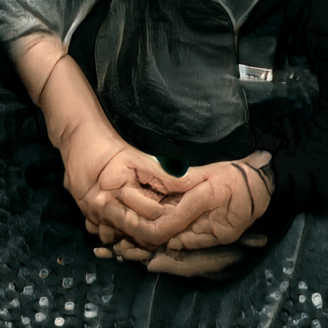
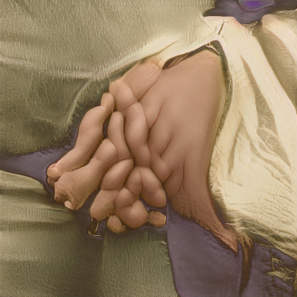
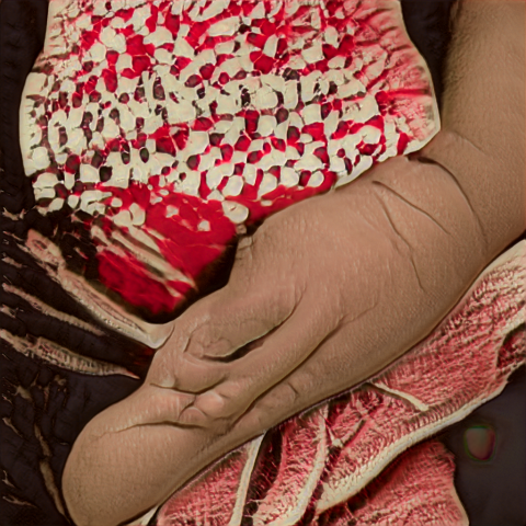
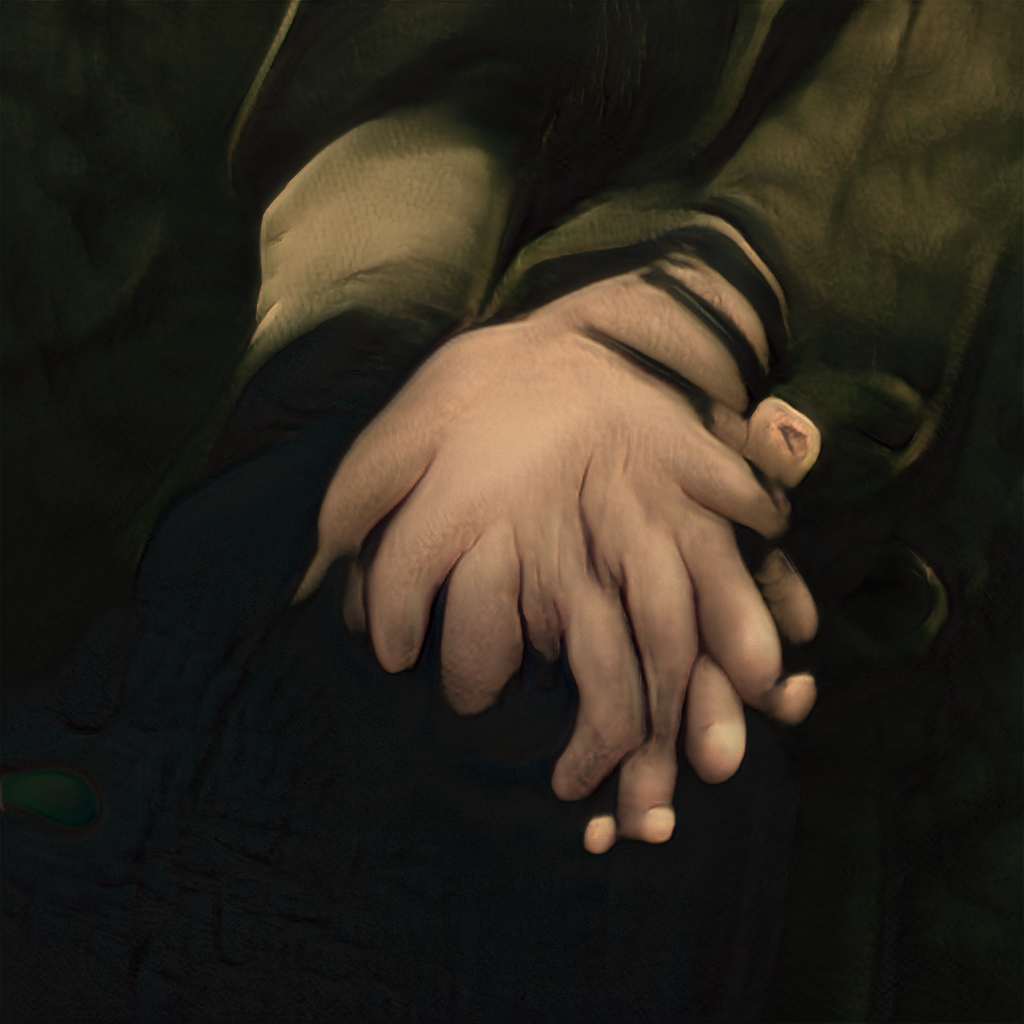
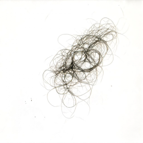
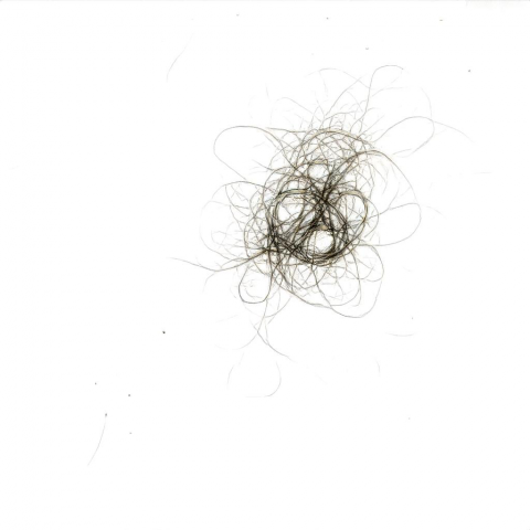
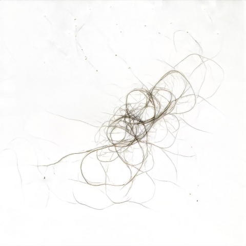
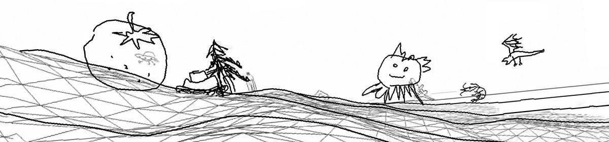
Here is a funny looking image represent the projection of our screen space reconstructed environment onto the “camera” at the sun. The actual projection looks like this:
  // SHADOW STUFF
  vec3 clipSpace = vec3(tex, depth) * 2.0f - 1.0f;
  vec4 viewW = gbufferProjectionInverse * vec4(clipSpace, 1.0f);
  vec3 view = viewW.xyz / viewW.w;
  vec4 world = gbufferModelViewInverse * vec4(view, 1.0f); // move from eye to feet - Minecraft's world space
  vec4 shadowSpace = shadowProjection * shadowModelView * world;
Yes. The inverse of projection matrix. Although it is not invertible, it can still reconstruct some part of the world we see on screen. This is exactly the reason why we save time in deferred rendering.

After that, we compare the depth value using step function instead of a branch:
float shadow = step(sampleCoords.z, unclippedShadow);

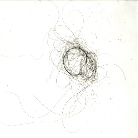
Notice the shadow has strange z-fighting looking pattern because half of pixel think there is something in between it and the sun due to floating point precision error.

We fix it by adding a small constant.
float shadow = step(sampleCoords.z - 0.001f, unclippedShadow);
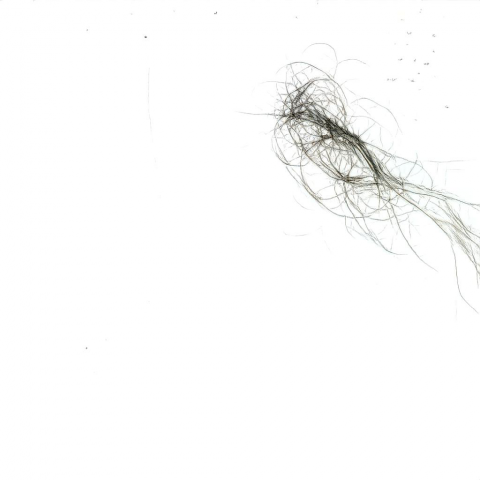
But the shadow is rounded. This is due to the low resolution of the shadow map. The resolution is related to screen resolution. Because the sun is very far away and it need to capture the entire world loaded, shadow near us is only represented by a few pixels. Therefore, we need more resolution near the player and less resolution for far away shadows.
For both shadow map creation and sampling, we distort the shadow by stretcing the center.
vec2 distortPosition(in vec2 position) {
  float centerDistance = (abs(position.x) + abs(position.y))/2.0;
  float distortionFactor = mix(1.0f, centerDistance, 0.9f);
  return position / distortionFactor;
}

Now the shadow looks better. But the shadow still seems too sharp near the edge. We will fix it later. // TODO: future direction
Implementing Gamma Correction and Dynamic Lighting
The world doesn’t look too good because we changed the way we render Minecraft completely. Time to fine tune some color. Here is how default Minecraft looks like.
This is what we got now. Although it is at noon, the sun light is sharp enough, but since we don’t bounce light, the shadow can never be lit by the sun. We need to simulate non-dirrect lighting by adjusting ambient lighting according to the sun position and correct gamma.

Some gamma tuning:
float light = sin(float(worldTime)/12000.0f * PI);
float ambient = clamp(light, 0.0f, 0.2f);

...

vec3 albedo = pow(texture2D(colortex0, tex).rgb, vec3(0.7f));

Implementing Focus Blur
We first try to implement Gaussian Blur. Although ideally I would use Gaussian distribution, but gaussian distribution is too complex: it joint p.d.f. (because we need x and y) involves multiple computationally heavy powers and divisions and it doesn’t have c.d.f., so I simply use distance to approximate.
vec4 albedos = vec4(0.0f);
  float totalWeight = 0.0f;
  distance(vec2(1.0f), vec2(1.0f));
  for (int i = -BLUR; i <= BLUR; i++) {
    for (int j = -BLUR; j <= BLUR; j++) {
      vec2 shift = texcoords.st + vec2(float(i)/screenShift, float(j)/screenShift);
      float dist = distance(texcoords.st, shift) + 1.0f; // add 1 to avoid division by 0
      totalWeight += dist;
      albedos += texture2D(gcolor, shift) / dist;
    }
  }
  vec4 albedo = albedos / totalWeight;

However, there are 2 issues:
L2blur has some transparency issues near edge of renderer.- It jumps too quickly when eye moves fast. I guess it needs to be implemented between frames for smooth gradual blur. The say way you would implement motion blur.
Done
And then we are done for today. There are many, many more improvements and many many ideas I haven’t tried. Some basics are: soft shadow, water reflection, water refraction, bloom. I was researching on Screen Space Reflection (SSR) for water that involves ray marching.