Dining v2.0

This project plays with the idea that was we give our technology the agency to think like us, we also give it our own human flaws.

Therefore I’ve made an ‘IoT-ized’ dining set, featuring a knife and a fork that have been upgraded to improve the user’s dining experience.

The dining set features an eco-friendly knife that you must pump yourself, and a fork that gets a bit nervous when it comes down to stabbing food, and therefore tries to avoid its responsibilities. The fork is plagued by a fear of failure, so it avoids its work rather than attempts to do its job. The knife is afraid to take creative liberties, and so you must instruct it exactly where you want to go.

Demonstration Video:
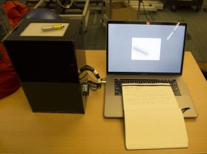
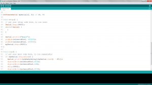
Code:

Silverware_Code

Making the Fork:

I initially prototyped the fork with a plastic fork, a servo, an arduino, and a tilt sensor. I used a straw to provide resistance, cutting the fork in half and allowing the servo to pull on a string that moved the fork down on command.

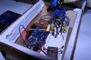
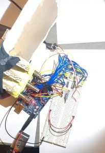
I found some springs, and found the motion to be more organic, making it seem as though the fork had life of its own. For the show, I used an Arduino Pro Mini and soldered it to a tilt sensor and to a servo attached to a larger metal fork. By connecting a spring between a cut off fork head and the fork base, and attaching this spring to the servo, I could cause the same motion as the prototype and move the fork.

Making the Knife:

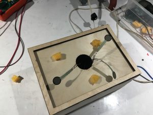
I 3D printed a gearbox for a servo that translated rotational to linear motion. (STL files here)

Then I soldered together an Arduino Pro Mini, a 100k ohm sliding potentiometer, and a servo, and mapped inputs from the pot to rotation (and thus linear motion) from the servo. I split a knife in half and attached it to the end of the linear actuator and the handle to its base.

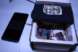
For both of the utensils, I molded a handle out of InstaMorph, and used it to hide the electronics of the devices. I then wrapped that in electrical tape, mimicking the way sensitive electronics are packaged in devices (for example, batteries or ICs), as a way to highlight the difference between how ‘techy’ devices are constructed versus how the target audience perceives them.

I had also worked on the gearbox for a jigsaw knife (a knife that moves in a similar way to a jigsaw blade), as an example of an overenthusiastic and unnecessary device, but had trouble attaching a motor to the gearbox.

I used this gearbox, and laser cut a baseplate to attach to my motor. I also made a D-shaft to Hex shaft couple out of acrylic, so that the motor shaft would nicely fit into the gearbox assembly, but the motor managed to break through the acrylic due to not being aligned properly when drying. Unfortunately I did not realize the repeated cause for stalling was due to misalignment, and when I tried to glue it again in the correct alignment, it dry a little bit off center.

Bryt 3.0 – An Endless Melody – Final Project

For my final project, I explored music visualization with the arduino with LEDs and mirrors to create unique visual effects. My project has the ability to visualize music on the go through a 3.5 mm audio jack.

******VIDEO IS NAMED: PLAY_ME.MOV*****

https://drive.google.com/drive/folders/1vrhpKTf6-6S3frgSOLTRx7zvACegf1nk?usp=sharing

About:

For my final project, I was really interested in music visualization and sound representation so I decided to build an Arduino-controlled LED music visualizer. I got most of my inspiration from the lights in the Hunt library’s stairwell but wanted to make something different.

So I made a light-up infinity mirror from clear acrylic, an LED strip, a 2-way mirror film, and some super-reflective mirror sheets. The lights surrounding the mirror are RGB, fully controlled with the Arduino. The flashing and color changing of the lights correspond to the music in real time.

In order to get music visualization working, I used a microphone that listens to songs played from the speakers and interprets when the bass is running. From then, I just programmed the Arduinos to change the colors of the LEDs depending of the music.

Final Crit: Children’s Fish Tank


For my final version of this project, I focused more on creating a cleaner final product than I had in past projects  — mainly, I wanted to hide all of the wires and mess.

**Also, I unfortunately couldn’t devise a way to bring my fish tank to campus without potentially killing my fish (which I’d rather not do), so I had to improvise with the vase and jello/Swedish Fish that you see above (this also really hindered me in creating the feeding-contraption, since the vase I used is rather narrow-necked).

gnolan Arduino code


depth mirror: final

Overview:

I intended to create an 2D array of solenoids that would respond to changes in depth input through a kinect. It would essentially reflect the depth in the image captured by the kinect. However, I found it very difficult to take input from the kinect and send this data to the arduino simultaneously, so instead I first record a history of depth data from the kinect, and then send it to the arduino via bluetooth, which it then uses to move the solenoids.

video showing this process: https://www.youtube.com/watch?v=fpj6dSkBT7g


Hardware and form:

I created CAD models (in the files attached with this submission), which consisted of three acrylic tiles per solenoid. The two below would have had holes in them to allow the solenoid to move. However, the 5V solenoids I had planned using grew legs and walked away, and this design was inapplicable to the 7V solenoids I ended up using.  (the brainstorming process and design is attached with this submission)

Circuitry:

circuit board I made for 4×4 array of 5V solenoids:

finished  2×3 array of 7V solenoids I was forced to use:


Issues I faced:

  • I spent a lot of time trying to figure out how to get depth values from the kinect. I also had a lot of issues with serial connection between my laptop (mac)and the arduino. I finally somewhat resolved this by using software serial with bluetooth. However, as previously mentioned, I had to write another script in python to send the data across the serial connection.
  • I was scavenge for and use 7V solenoids instead of the 5V ones as I had initially planned. This took additional time and configuring.

Acknowledgements:

I would like to thank ideate for providing me with the parts, Akshat Prakash for helping me with the software serial, and Bolaji Banakole for giving me his spare arduino when I fried mine.

link for other documentation, code and CAD files: https://drive.google.com/file/d/13e1UmHgjkUIJSzP44gxqSoUB4iE-ZnXS/view?usp=sharing

Final Crit: Gaurav Balakrishnan

Confused Keyboard 

My initial project idea was to just make an instrument that makes people think by being not unlike what people expect. I decided to make a keyboard which looked exactly like a functioning proper keyboard but emitted noise that were slightly off. While the major idea remains the same, I noticed that this would be a very interesting model to mimic very real occurrences of things and people having perfect external appearances but functioning in confusing ways. The keyboard I have finally made is very confused most of the time, playing notes with frequencies slightly off, with tones that are varied, with different and dynamically varying magnitudes. All of this happens without any apparent pattern. However, every so often there is a period of lucidness that can be experienced where the keyboard plays exactly like one would expect. To someone who reads and learns about neurodegenerative diseases, this is a very relatable phenomena.

Components:

An old Yamaha Keyboard
Conductive Copper Foil Tape – Switches
8 ohm Speaker
Wire
10k and 15k ohm Resistors
Arduino Teensy
Class D Amplifier

Iterations

The first draft of this project was conducted with just a couple of breadboards, lever switches, and an Arduino Teensy using the DAC to output waveforms. A code was implemented to dynamicallyh randomize the kind of notes played on each key to show a proof of concept of how the project would work. The image below shows what the circuit looks like.

The Final Project 

I decided to try and obtain an actual keyboard to use as a shell and the form for my project. I had two options on how to move forward with it – 1. to access the key reads using the circuits that exist on the keyboard and, 2. to completely rip out all the electronics and implement simply design switches to read using the Teensy. The latter option was selected because it proved to be slightly complicated to figure out the wiring of the keyboard’s electronics. Also, I decided to implement only an octave worth of keys but focus more on the software of the sounds generated by the keyboard. A limitation of the Teensy is also the number of inputs.

The switches were implemented using Copper Foil tape applied on the keys and in a power line running in the bottom where the keys would make contact as seen in the image below.

A challenge I ran into was on understanding how to make these switches function in a more reliable manner. I found that reinforcing the foil by applying multiple layers was really helpful.

The code is uploaded here. I think it was really interesting to use a DAC to produce waveforms and directly manipulate them to create various effects.

The video is here!

Bolaji Bankole: Final Project

The concept that I set out to convey with my project was distractions and apathy preventing you from achieving what you want/need.

I set about doing this by creating a robot that would meander towards various targets, and you can interfere and distract it along the way. In the end there is some overly interesting behavior, but for the most part it works.

The bot was controlled by a raspberry pi using openCV, and each target had an arduino pro mini with a neopixel and an IR range sensor.

While it mostly worked, there were still a couple of issues that I ran into. The internals of the bot are a mess:

With most of the space allocated for a battery that I’m still having power regulation issues with, so it may remain tethered to a power supply.

video 1

video 2

video 3

Assignment 8: Final Crit on “Draw Your Music” (SooJin Sohn)

DRAW YOUR MUSIC

My final project, in short, lets a webcam to scan and utilize a drawn image from a user, then output it into audio.

Description

Specifically, this project connects with both Arduino and Processing, which activates a webcam to color track the color of a red laser pointer, locate its coordinates within the camera vision range, and translate that into audio ranging from 100Hz to 500Hz. The audio plays on a real-time basis, through a 8-ohm 12-watt speaker. Finally, the power is sourced from my laptop.

Major Changes

Initially, the plan was to have a usb web camera to make a screencap of a fully colored, hand-drawn image, then auralize it using Arduino’s pitch files. I have been spending the past 3 weeks to code 5 different

The biggest challenge and the problem was to merge all codes into one, where captured webcam image data had to all be converted from 2d arrays into bytes. Audio data was hard to manipulate with byte type data communicated through Processing.

Having to realize very late, I decided to simply the idea of screen capturing and analyzing web camera monitors. Thankfully, as I was simplifying the codes I had, I also learned that I could make a more interesting form of interaction. Specifically, I ended up creating a semi-tangibly interactive object, where the user shoots laser beams to interact with the machine, using a laser pointer instead of his/her hands. This was also funny since, this final format was rather very close to my very initial final project idea, where I was attempting to make a theremin-like guitar, that used a laser as a main playing tool.

Reflection + Future Plans

After finishing project, I am now having hopeful thoughts about actualizing my very initial final project idea of making a laser-guitar. I would use some slick-colored acrylic boards to cut an electric guitar, with a translucent white acrylic, interactive tracepad attached in the middle instead of 6 strings. I would 3d print, or laser cut a guitar pick that would function as a laser pointer on its own. Lastly, I would change my selection of web camera, where I can manually fix its focus setting and vision range. ( this will ultimately have me achieve a design where the webcam can still be located closer to the interaction panel)

Documentation on Google Drive(Code/Pictures/Video): https://drive.google.com/open?id=1_hBXMw25CjPZ_EIG4wJ7HDTKHdAacyU6


BrailleTutor – Final Project – Akshat Prakash

BrailleTutor

Concept

The idea is to help in the adjustment-to-blindness training programs to allow “adults who originally learned to read print but lost their sight later in life” to learn braille.

Components

My braille system consists of a braille pad, that is an Arduino controlled six solenoid pin arrangement that creates one braille letter/number at a time. The system also consists of a companion android app that pairs with the braille pad to conduct lessons for the user to familiarize themselves with braille.

Walkthrough

The app consists of three modes. Learn, Test and Refer.

Learn allows you to learn numbers and alphabets paired with the braille pad. A letter/number is spoken and appears simultaneously on the braille pad.

Test allows you to test how well you have learnt numbers and alphabets. A letter/number appears on the braille pad and the app prompts the user for an answer, then giving feedback.

Refer allows you to refer to the braille representation of any number/alphabet in the English language. The user says a character and it is presented on the braille pad.

With this project, I could achieve harmonic communication between the android app and Arduino and synchronously generate alphabets in conjunction with the corresponding braille translation of the alphabet.

Simple Working:

Final Overview:

Issues and Conclusions

The issues I faced were those related to power, design and over-heating solenoids. I used a 12 V DC adapter to power the solenoids and made their action synchronous to generate the braille character.

All in all, I think this was a very satisfying project. I feel I have learnt enough in this class to take an idea and actually create it. Thank you!

Entire project folder:

https://drive.google.com/drive/folders/1rIW53AoUlIqoe380YHmB_wtATQnuxXon?usp=sharing

Scott Final Project

Initially my idea was to create a text to speech keyboard in order to give the anyone with fingers the ability to speak. I found libraries that worked for this, as well as the speaker and power components  I struggled with the keyboard part of the project. After researching online I thought I would be able to use an old school ps/2 connector keyboard with a library I found but I struggled with making the connection perfect with the pins. So I bought a piece online that would do this for me. When it arrived, I tried to get it to work the same way I saw it done online but finally gave up after some fruitless time debugging as well as seeing a few people online with the same issue (never being able to see power in the keyboard) and no known solution.

So I pivoted to making my own controller with force sensors attached to a spongey material underneath a flexible material that the user could push down in different spots on

Then I was able to use the varying sensor values for when the user pushed down in 7 different spots to get 7 different “keys” from the 3 sensors while still being able to know where the user is pressing. Since the mid point I added volume to the speaker with a LM386 audio amplifier as well replacing the power so the circuit could be plugged directly into a wall outlet.

The last touch which was something I had never done before was lazer cutting the box that I put everything inside of. I from an online box-generating site where I entered the dimensions and it gave me a .svg file. I then used illustrator to add the additional circles I wanted cut in certain walls for the speaker and wiring and export the file to use on the lazer cutter.

download code/fritz: codeAndFritz