Assignment 7: Gaurav

My idea is to make a keyboard that is a symbol for confusion. It’s exterior will look perfectly alright but on playing it, the user will find that the keys produced tones completely different from what they expect. And the tone that each note plays varies in random time and there should be no seeming pattern in the confusion. However, there will be brief periods were the keyboard will be lucid  again – allowing the user to savor the few moments of normalcy before it is consumed again by its confusion.

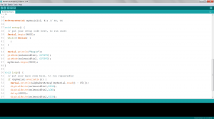
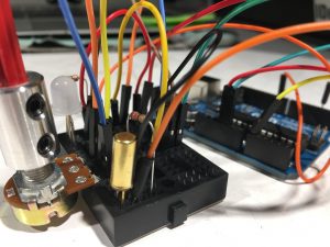
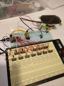
The project as it stands lacks form. I decided to focus on making the essentials work and efficient code for the first draft of this project. An Arduino Teensy is used to create different types of waveforms that can be outputted through its DAC. The signal from the DAC is amplified using a standard 2.5 W Class D amplifier that then connects to the speaker. The Audio library proved to be extremely helpful in the creation and the handling of the waveforms. It took a lot of time and effort to troubleshoot and create the output of waves from the DAC and then in using the amplifier chip. However, many trivial but crucial mistakes were found that when fixed allowed the system to work quite well.

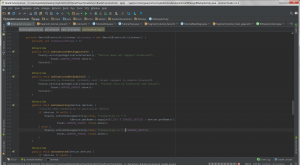
Writing the code has been one of the more challenging parts of this project. I have learnt a lot from observing how changing code in one part of the program can affect the function of all other parts. Also, I noticed that every time I added a functionality in the code, there were new edge cases that I needed to account for. This has been a great learning experience.

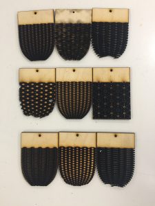
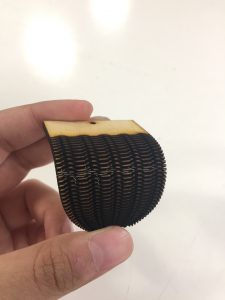
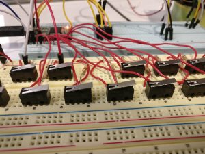
The next thing I want to focus on is the form of the project. My ideal path forward would be to obtain an old, cheap keyboard and strip off most of the electronics to access just the keys. I would then be able to connect the keys from the Arduino and control the sound exactly the way I described above. If this proves to be very hard, I would like to fabricate a simple but appealing keyboard using laser cut wood or acrylic.

Video 1: Perfect Sine-wave based polyphonic synthesizer

Video 2: Confused Piano
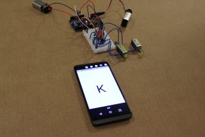
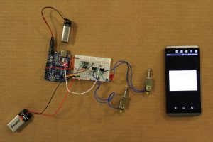
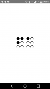
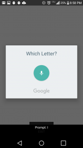


Assignment 07:

Updated Hourglass Concept:

An hourglass that resembles how time is passing in its environment. The speed of sand falling depends on how much movement occurs around it.

Rough Draft Prototype:

Sketches are developed that outline the overall form of the hourglass, including how the technology will be embedded in the form. I used a previously made model of a laser cut aperture to change the amount of sand that will potentially flow through. I still need to add another cover for the lens so the pieces do not fall out, especially when the hourglass is flipped. I also need to solidify how the tech will be securely (drilled?) into the wooden casing. I am also considering adding another variable (ex. sound) to control how the sand will fall (not sure if it will get too complicated if I want to affect how the sand falls, rather than just the amount of sand falling).

To Do:

  1. design the enclosure that will hold the glass form
  2. Have people test out form and see if it is understandable / has the right affordances
  3. Fix all the things that didn’t work
  4. repeat 7 and 8 with a few other people
  5. make an information poster for the final show
  6. write up my artist’s statement for the final show

Transistor Sword Rough Crit


https://drive.google.com/drive/folders/1Xv4OfpfIbuqn6w5a-yl5K2HX8IPY0XIM?usp=sharing

Difficulties:

Transistors:It so turns out that the MOSFETs were not very functional transistors, and a Darlington Array transistor (UM2003) was used instead. Independent continuity of each R, G, B, pin and MOSFET circuit was tested, but there seemed to be a perpetual issue with connectivity. The lights responded well to code after the switch to the Darlington Array transistor.

Pulse Sensor: The pulse sensor used the code from Pulsesensor.com but the threshold was set at 550, while the readings from the pulse sensor ranged from 900 to 10, since there was much noise. Even if someone’s hand was close but not on the sensor, a “pulse” was detected. To prevent the lights from pulsing when there was only noise and no real pulse, I included another pulseSwitch, a momentary switch that had to be activated, in addition to the corruptSwitch being inactive.

Getting Corrupt Mode (corruptSwitch == LOW)  to stay red: I have some trouble writing the code to exit the loop and end with the LEDs staying in the red state. I tried using booleans and conditionals but can not seem to get it right.

The circuitry has been completed for this project but the code could use some tweaks.

Assignment 7: Mechanical Flower prototype

For the rough crit I have a cardboard prototype of my interactive mechanical flower. Currently it has two axes of motion:

  • the flower opens and closes based on distance readings from an ultrasound distance sensor (opens when you are close, closes when you are far)
  • raises or lowers with a linear actuator (nut and bolt)

Video: https://youtu.be/9XyJqv4cWkE

Fritzing and sketch: final prototype

Overall, I’ve gotten down the basic range of motion I was going for. However, the motor is too slow even with increased voltage so the raise/lower motion is not very noticeable (in the video, it’s very slowly rising) and a faster motor wasn’t strong enough to carry the weight. I also don’t really like the way the motion looks. Because of this I am considering removing the linear actuator part and focusing on interaction with just the flower.

Next steps:

  • work on form (make the flower look nicer with wooden petals, covered center, etc., replace cardboard with wood/foamcore)
  • add interaction to the petals besides distance (touch)
  • if I’m keeping the linear actuator, find a way to make the motion smoother and faster

Braille Tutor – Rough Crit – Prototype – Akshat Prakash

  BrailleTutor

In this rough crit, I aimed to create my minimum viable product and prototype for the Braille Tutor.

Concept

The idea is to help in the adjustment-to-blindness training programs to allow “adults who originally learned to read print but lost their sight later in life” to learn braille.

Components

My braille system consists of a braille pad, that is an Arduino controlled six solenoid pin arrangement that creates one braille letter at a time. The system also consists of a companion android app that pairs with the braille pad to conduct lessons for the user to familiarize themselves with braille.

Prototype

The prototype, for purposes of the rough crit, consists of two solenoid pins controlled by an Arduino that pairs to my companion android app. The prototype does full justice to the proof of concept. I could achieve harmonic communication between the android app and Arduino and synchronously generate alphabets in conjunction with the two braille pins simulating the actuation of the corresponding braille translation of the alphabet.

The first lesson learn, displays an alphabet on the android screen and speaks it out. This is then communicated to the Arduino which actuates the pins (in the final version, I will have the rest of the four pins) in a 3D printed casing.

The second lesson generates a braille alphabet on the braille pad and asks the user to identify it.

I have more ideas for several lessons/braille dictionaries for the app. The final product will simply include these lessons and the rest of the four pins, enclosed in a professional casing.

Issues

The issues I will face are those related to power. Six solenoid pins are going to be using a lot of power and I need to find a way to make this more power efficient.

Video

Link to entire project folder (code and video) (May take upto 5 minutes to download):

https://drive.google.com/drive/folders/1sh-SdU1qkmg7sEIWPwzjY_qnY8RJJ0P4?usp=sharing

Assignment 7: Heartbeat Bear checkpoint

To re-iterate the project intention:

The intention of this project is to develop a children’s soft good that serves as a grounding mechanism for young children who are overly anxious. Grounding mechanisms are used to manage anxiety by creating a movement or feeling to anchor someone back to the environment.

I am using a pulse-sensor and speaker for this project at the moment- I became interested in the tangible movement the speaker generates when electricity runs periodically through it and used it as the output for the pulse readings.

Overall, this checkpoint was a success in getting a basic program and functionality to work. I experienced a few problems reading the pulse sensor as the data is overly sensitive and am still working on making this more fluid. I am also experiencing a slight inconsistency with the beating- this is likely due to code troubles which will need a bit more time debugging.

Buggy heart-beat reading; using an LED

Buggy heart-beat reading; this one’s just fun 

Next steps after cleaning the program and establishing something more robust would be to start housing the electronics and placing it inside a stuffed creature. I am unsure if I will be purchasing a stuffed animal at the time or creating my own- I’d like to first define where to place the pulse sensor that would be most effective.

code

video 1 (apologies for background noise)

video 2

Final Project – Rough Crit

For my rough crit, I have a prototype of the mechanical “worm” that can move in a couple of dimensions and is actuated by the Arduino. Moreover, I have also ensured that I can get data from an IR sensor and a microphone, but will need to choose which sensor to use based on the final form of my tank.

The mechanical form took a great deal of prototyping to figure out a good mix of flexibility (especially in multiple angles) as well as durability, as I found out rather painfully that many of these patterns broke rather quickly. Moreover, another trade off became very apparent with weight and movement, as not only did it require more strength to move but also it means I have to tamp down the other part of the board.

Additionally, I had originally planned to actuate the system using muscle wire, but it ended up being too weak to move the worm. Therefore, as a work around, I actuated the worm using string and servo motors – the servo motors pull up the string, which are attached to specific points around the worm and then pull up the worm accordingly.

However, I’m trying to get a more natural movement, so I might have magnets on the underside of the wood so that way there is only a small part of the wood that peeks up with every string.

Code: prototype

Assignment 7: smartCUP (phase I)

Video: https://drive.google.com/a/andrew.cmu.edu/file/d/1uJrMMaA4rdIBzo9_qtG1xPqMnSFyMKbV/view?usp=sharing

Smart Cup can currently do two things:
1. Tell if your cup is ready to drink; 2. Animates if you are drinkingTo achieve these tasks, my product has 3 component: a NeoPixel (8mm), a potentiometer, and a tilt sensor.

Problems I ran into/Lessons learned:

  1. LED vs NeoPixel
    Initially when I got the NeoPixel
  2. Tilt sensor
    Originally I was going to use an accelerometer to detect the cup’s motion in space. But then I realized I only need a True/False statement about whether the cup is tilt. so I used a tilt sensor instead.
  3. Transfering to small breadboard
    Originally, I got everything to work on a medium-sized breadboard. But my control rod of the potentiometer can only be oriented horizontally. See below video.
    Video: https://drive.google.com/a/andrew.cmu.edu/file/d/1Jj4yO0z1debjec-IqmifXLbTyK5yYWSA/view?usp=sharing

So I transferred everything to a smaller-sized breadboard, which allows my control rod to point upward.

4. Adafruit Gemma/ Teensyduino not working with Arduino
Now that I can fit the breadboard into the cup, I need to fit the arduino control in the cup as well.  I first tried Adafruit Gemma and got through the installation process. Unfortunately, the port cannot be recognized by my arduino.

Next I am going to try teensyduino. This will be the next step of my project.

Coming up, I am thinking about incorporating the following things:
1. temperature sensor
2. battery-powered
3. Proximity sensor: if there is the couple cup is nearby, the cup does something
4. Add customization