As a retinal degeneration patient, room lighting and eye strain have been two things that I have always had to pay attention to from a young age. Without good room lighting, my eyes can quickly begin to strain, causing cells in my retina to work in overtime and eventually die in a pattern that causes irreversible damage.
To combat one of the most important causes (at least in my case) of retinal degeneration- eye strain due to lack of lighting- I decided to make myself an LED ring that serves as a reminder to turn on the lights when a room is too dark to work in.
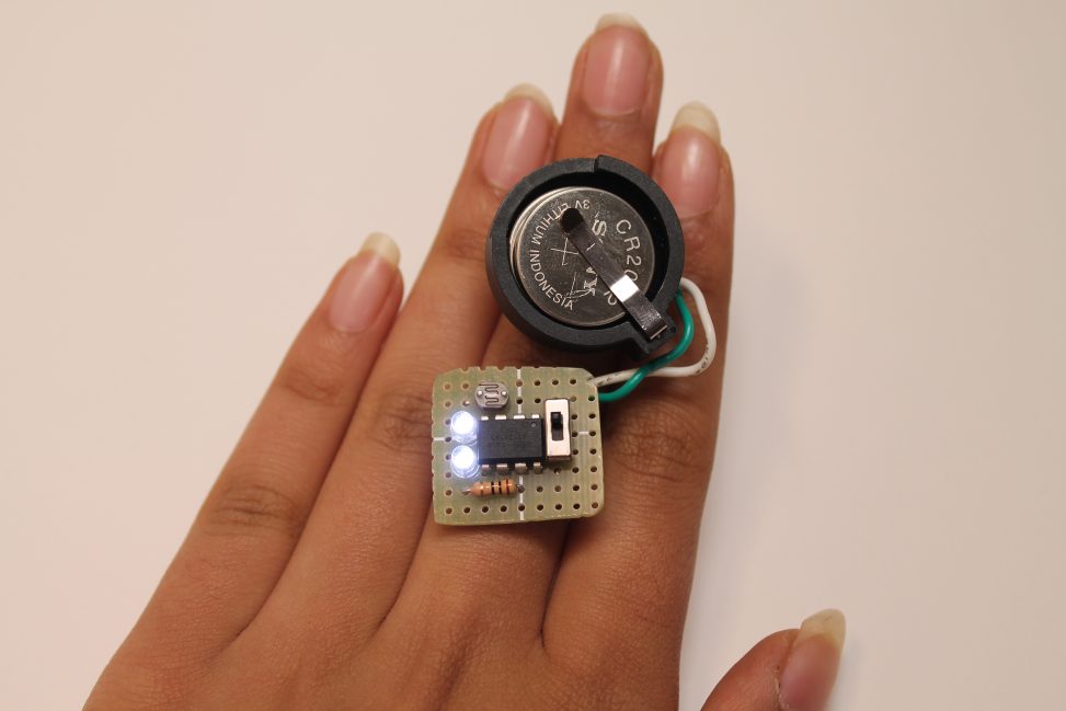
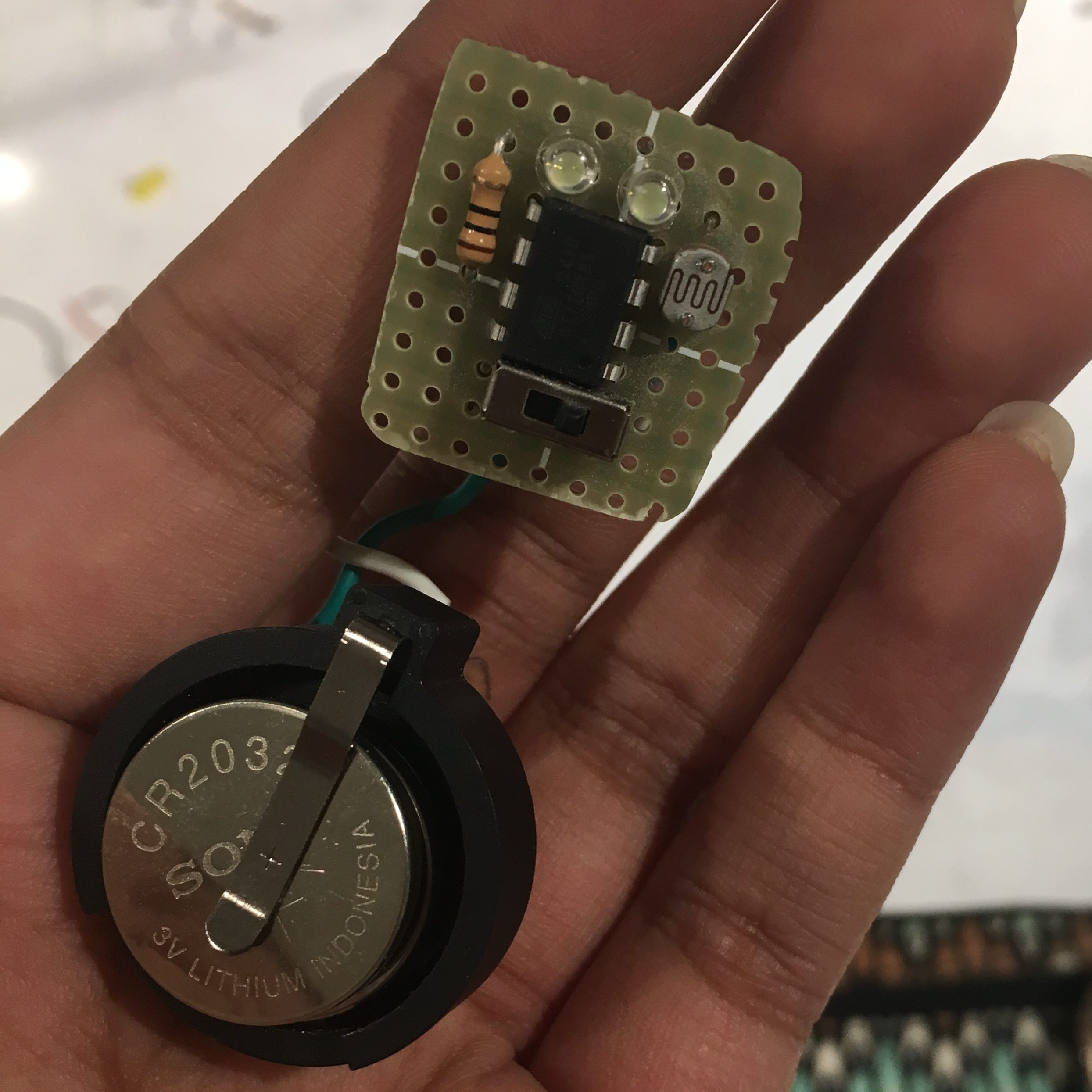
The ring itself consists of two main components- one is the circuit upon which the LEDs, Arduino, and photo resistor are mounted, and the other is the power supply for the ring.

The ring light is on- it’s too dark to work in the current room
The back of the ring is perfect to sit on my fingers.
The ring was an immediate idea that stood out to me because of its portability and subtlety. I could take it anywhere, and it would work anywhere. The biggest challenge I faced with it, however, was that a ring is very small (talk about a
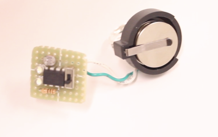
In this photo, the room is much brighter, so the ring light is off.
blessing and a curse). In the initial design phase, I almost scratched the idea because I wasn’t sure where the Arduino would go. With some additional research, however, I found that an ATTiny85 Microcontroller would be a perfect fit for the scale I was looking for. With 6 functional pins and the same electrical capabilities as a normal Arduino Uno R3, the ATTiny proved to be exactly what I was looking for. With help from a programming chip and some initial testing on an Arduino, I was able to easily write the code I needed for the ring.
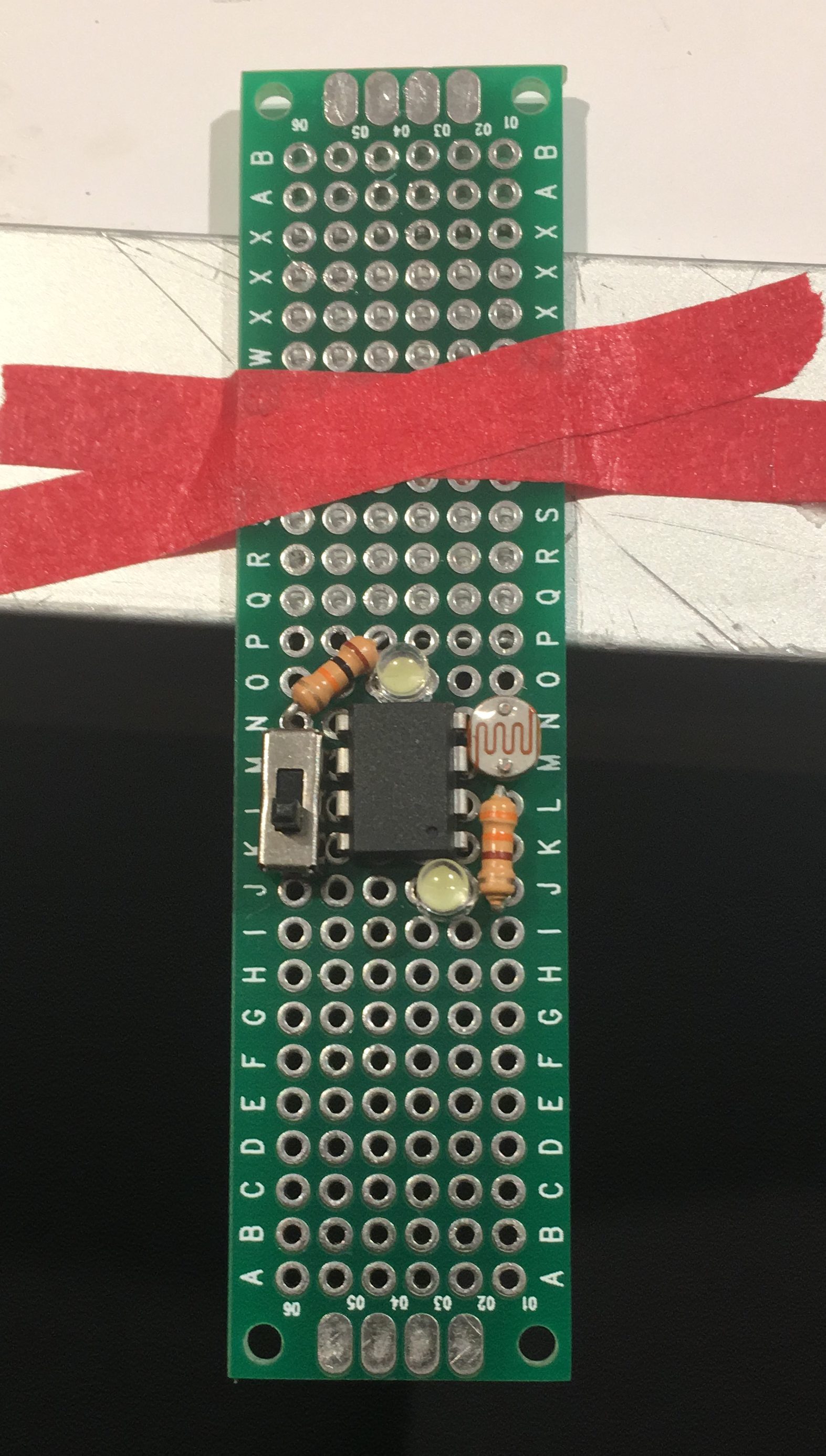
The biggest challenge I faced, however, came when it was time to build the circuit for the ring. A normal breadboard contains power and ground rails and is
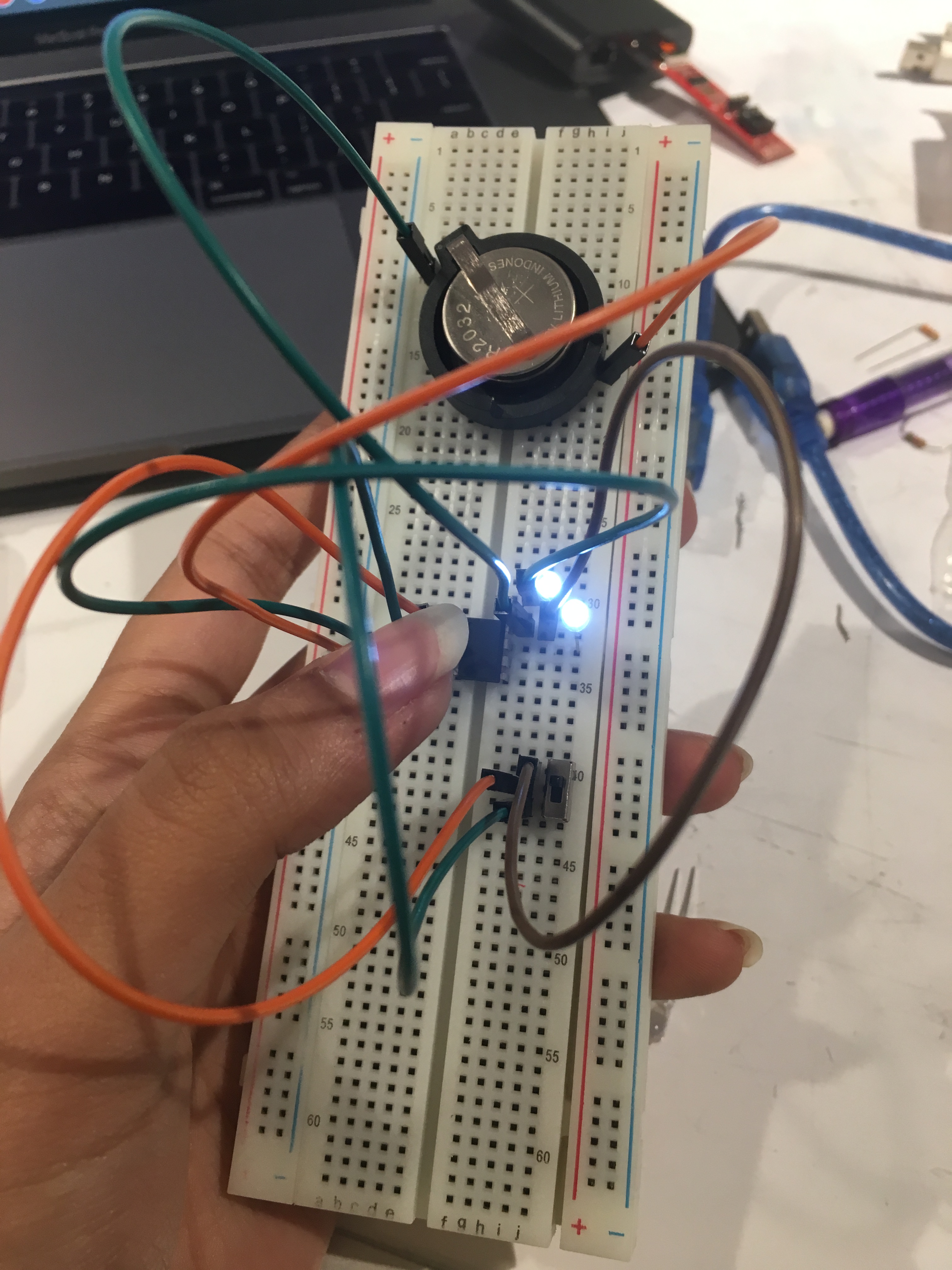
A convenient prototype of the project, which included luxurious ground/power rails
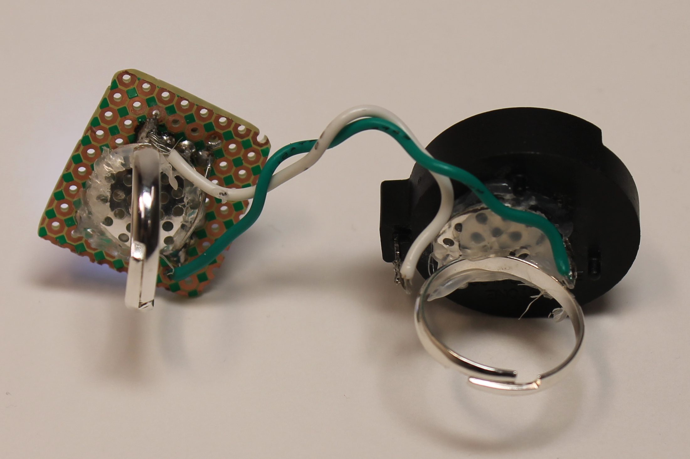
wired so that horizontal lines are connected. A board like that would take up too much space on my ring, so I had to use a board which had no connections on it to shrink the ring down to a size as small as possible. With that came two upsides and a very, very large downside. The upsides were that I could now fit my entire ring circuit into an area no larger than a square inch, and that the small size was perfect for a ring. The downside: every single electrical connection now had to be hand-soldered. With this challenge on hand, two of my weakest aspects- my soldering skills and my patience- were greatly tested (see failures below). Eventually, however, my final product was soldered and mounted after a hot minute with a handsaw.
This attempt failed because my soldering left no room for the Arduino 🙁
Another failed attempt- this time because I forgot to change the minimum resistance level from when I was testing threshold levels
With the final product ready, there remained a few design aspects which- given the time- I would have improved (my critique peers seemed to be in accord with these reflections as well). The first would have been the ring design. While the ring was small enough and portable, to me, it looked peculiar. I would have much rather had the circuit covered up so that all a person could see would be the photo resistor and the LEDs. In fact, my original hope was to make the ring look like Kate Middleton’s wedding ring (if you know, you know), but the required current on that was too much and couldn’t be supported by the amount of current supplied by the ATTiny. The next thing to change would have been the bulkiness of the ring. The ring was attached to another ring, which held the power supply. Given smaller materials, my hope would have been to move that smaller power supply to the main ring, so that a lot of bulkiness would have been lost and portability retained. Reviews suggested that the best way to do both these tasks would have been some 3D printing or maybe a larger jewelry item (bracelets, anyone?), but I did the most with what I had, and, frankly, I’m still proud to wear the ring whenever I need to judge the light (luckily, the ring has an inbuilt switch so it’s not on when I’m sleeping). Given the opportunity for a second iteration of this project though, these are definitely aspects that are important considerations I would make for a successful second round.
UPDATE: A couple of days after using this ring, a major issue with current allocation came to light. After approximately 72 hours of use, the batteries on the ring completely died. Some investigation revealed that the switch on the ring is logical, not power-related, meaning that the resting ATTiny, even when switched off, used up 3 milliAmps of current. A typical batter only lasts 220 milliAmp hours, meaning that 72 hours after the battery was inserted into the ring, the battery would die. An approach to solving this would such that the ATTiny ring code must be updated so that it goes into sleep mode (waking up only a couple of times per second to ensure no inputs), reducing current levels significantly. Thus far, changes have not been made to the Arduino code to handle this challenge, though an update to the code will be followed by an update to this post.
A video of the project in action (artificial darkness is created by my hand covering the sensor- I have given a side view so that the light can be seen) :
Code for the project:
/*
 * The following code block is for a ring that detects room
 * lighting and sends an LED notification if
 * it is too dark. It is powered by an ATTiny85 and a button cell,
 * a photosensor, and LEDs.
 *
 * NOTE: the serial monitor settings are commented out because the
 * ATTiny85 doesn't take Serial feedback. That said, if the code
 * was uncommented and uploaded to an Arduino Uno R3, the code
 * would produce the same behavior, but with Serial feedback.
 */

// set input and output pin numbers
const int PHOTOSENSOR_IN = A2;
const int SWITCH = 3;
const int LED_OUT = 2;

// set lighting threshold and timer variable
const int LIGHTING_THRESH = 150;

void setup() {
// set up the pin modes
pinMode(PHOTOSENSOR_IN, INPUT_PULLUP);
pinMode(LED_OUT, OUTPUT);
pinMode(SWITCH, INPUT);

// set up serial monitor for debugging purposes
// Serial.begin(9600);
}

void loop() {
  // check if the system is supposed to be on
  bool power = digitalRead(SWITCH);
  // Serial.print("system is on? ");
  // Serial.println(power);

  // if the system is on, proceed with light checking
  if (power != LOW) {
    // read the room lighting
    int room_lighting = analogRead(PHOTOSENSOR_IN);
    //Serial.println(room_lighting);

    // if it's too dark, turn on the LEDs
    if (room_lighting > LIGHTING_THRESH) {
      digitalWrite(LED_OUT, HIGH);
      //Serial.println("it's too dark!");
      }

    else {
      digitalWrite(LED_OUT, LOW);
      //Serial.println("great lighting for work!");
      }
    }
}
A schematic for this project is available here. Code is also available on GitHub.
Leave a Reply
You must be logged in to post a comment.