
An alarm clock that make noises and lights up when it is the time to wake up and can be only turned off my jumping on a pressure pad attached to it.
Final Product Images:
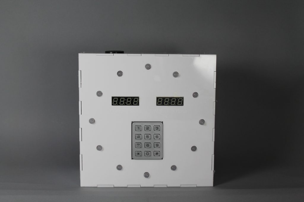
front view
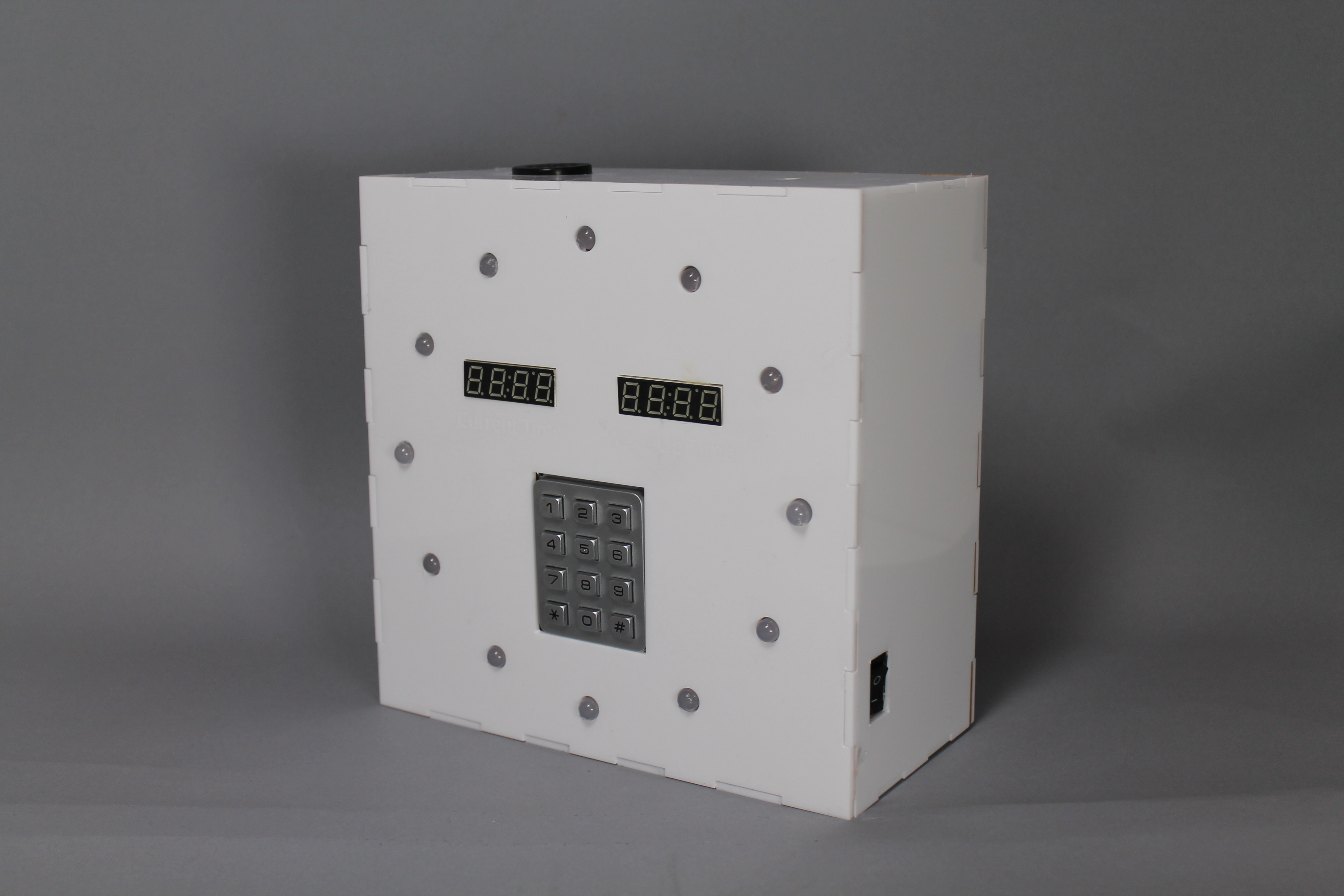
another view at an angle
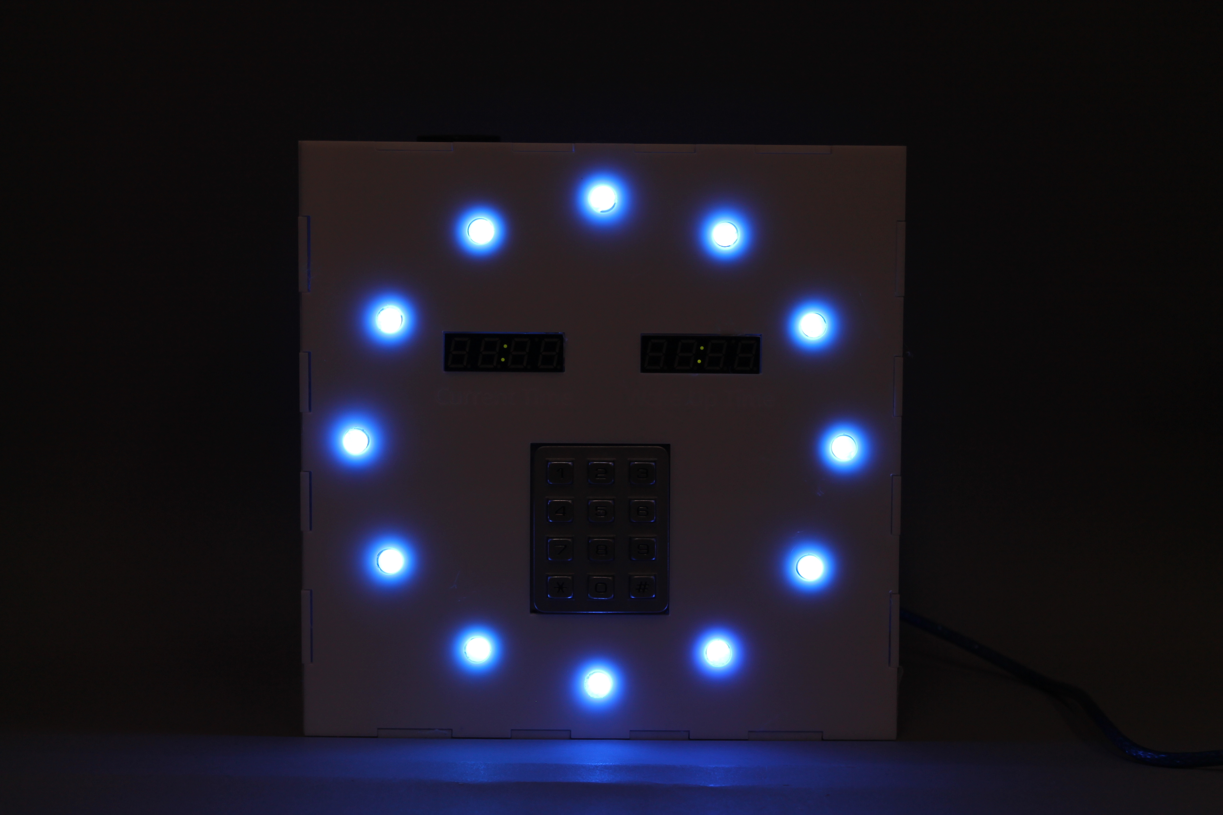
in the dark with lights on
the left time display should be showing current time, and the right time display be showing wake up time
periodic random changes in LED colors (the two lights on the left should be changing along with the others)
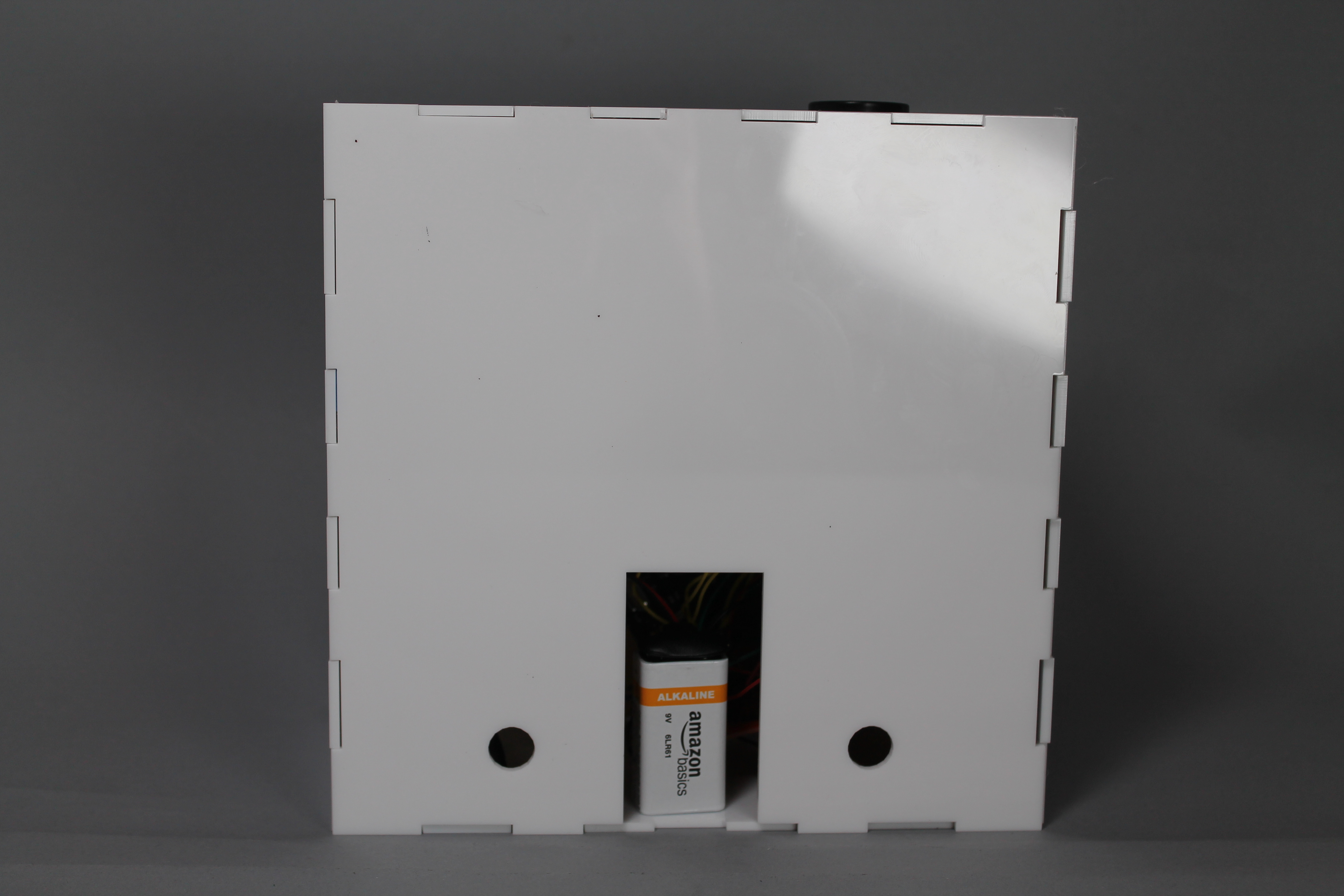
back view(the two holes were designed for the wires that connect to the pressure pad)
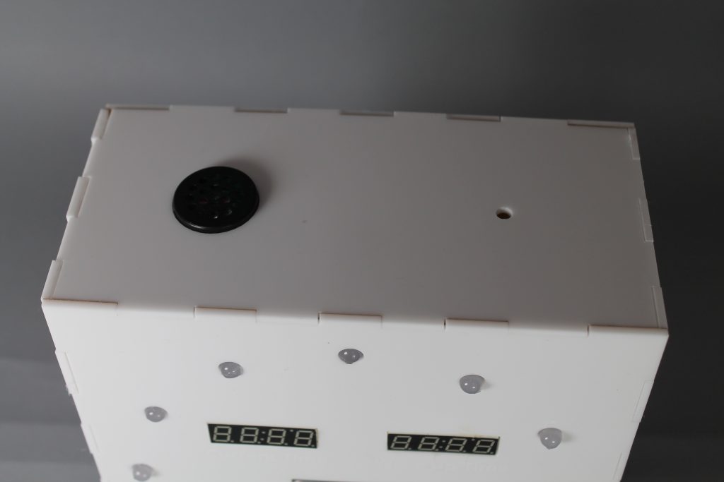
top view(speaker on the left and the small hole was designed for photoresistor)
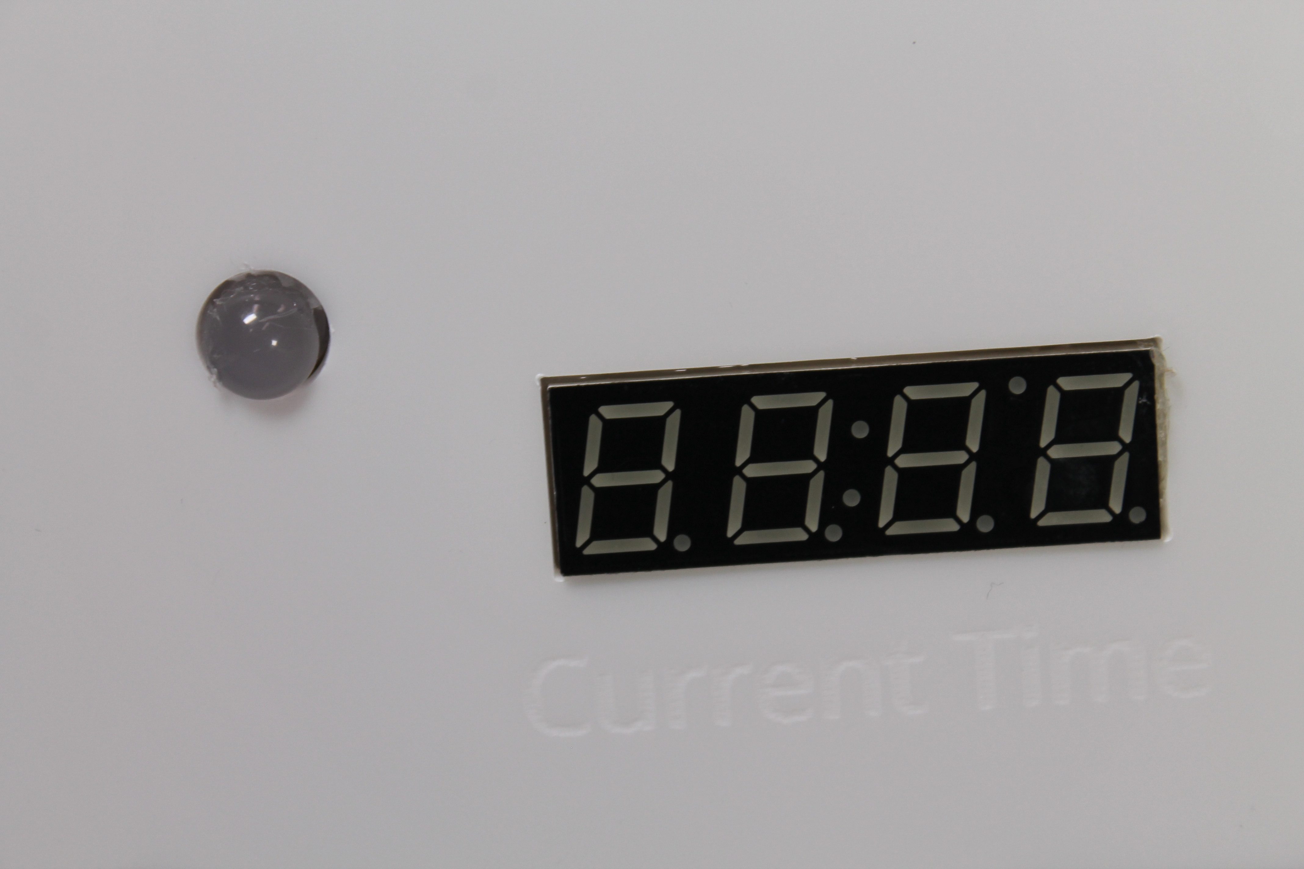
engraving details
Process Images and Review
Decision Point: Decided the functions, inputs outputs, and look of this alarm clock
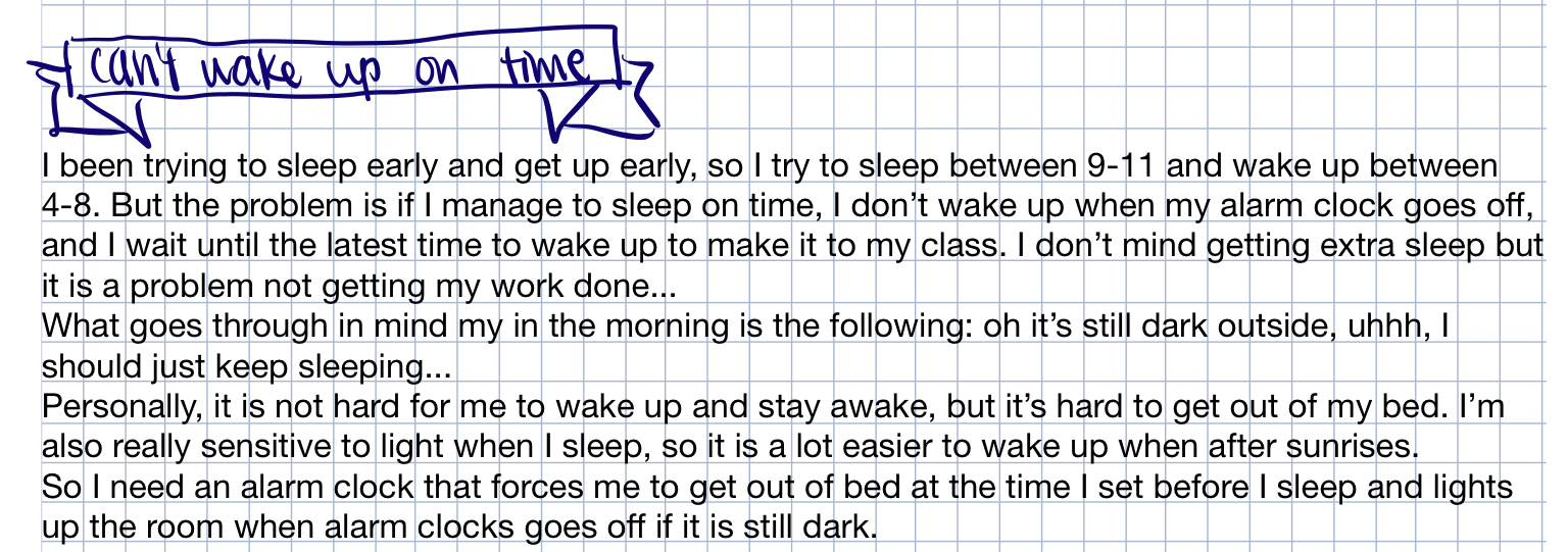
background story I jotted down to explore the possible features
After I found the problem that I want to solve, I identified a few functions I need of this alarm clock. First is to address that is it a lot easier to wake up after sunrises. I’m very sensitive to lights when I sleep, so any lights make it hard for me to fall back asleep. I decided to use LEDs. Then the problem was how to actually get myself out of the bed. I decided to use some force sensitive resistors as the only way to turn off the alarm clock.
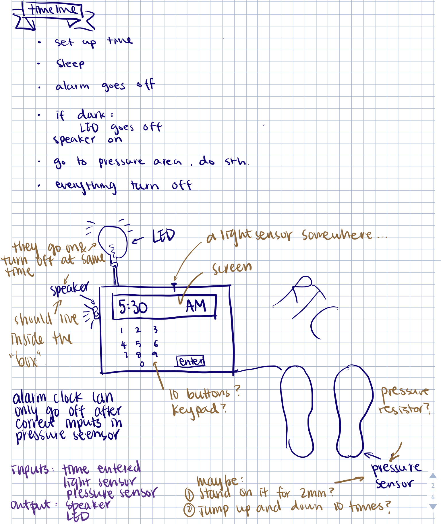
timeline, sketches and features
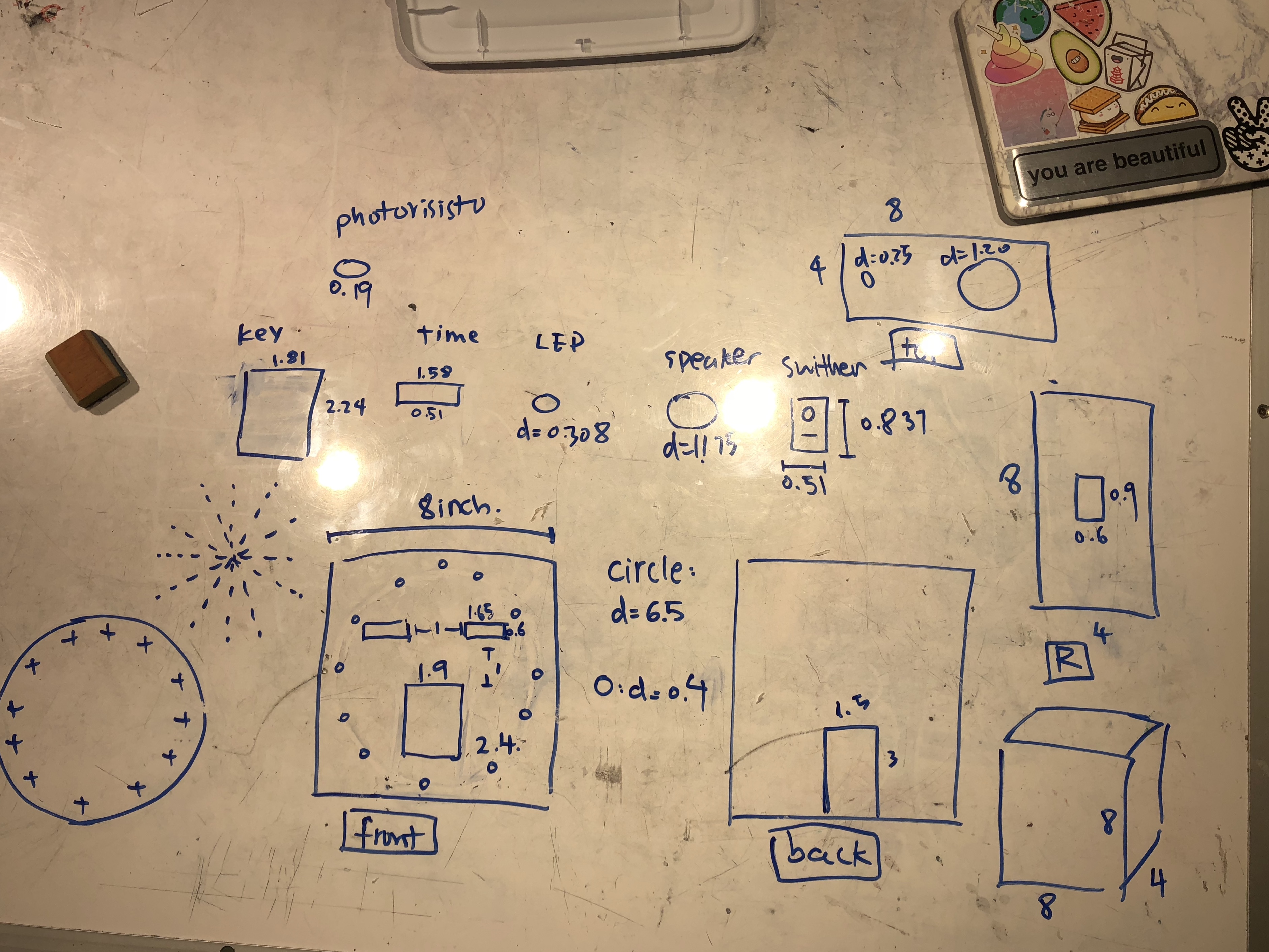
measurements of hardwares and final design of the box
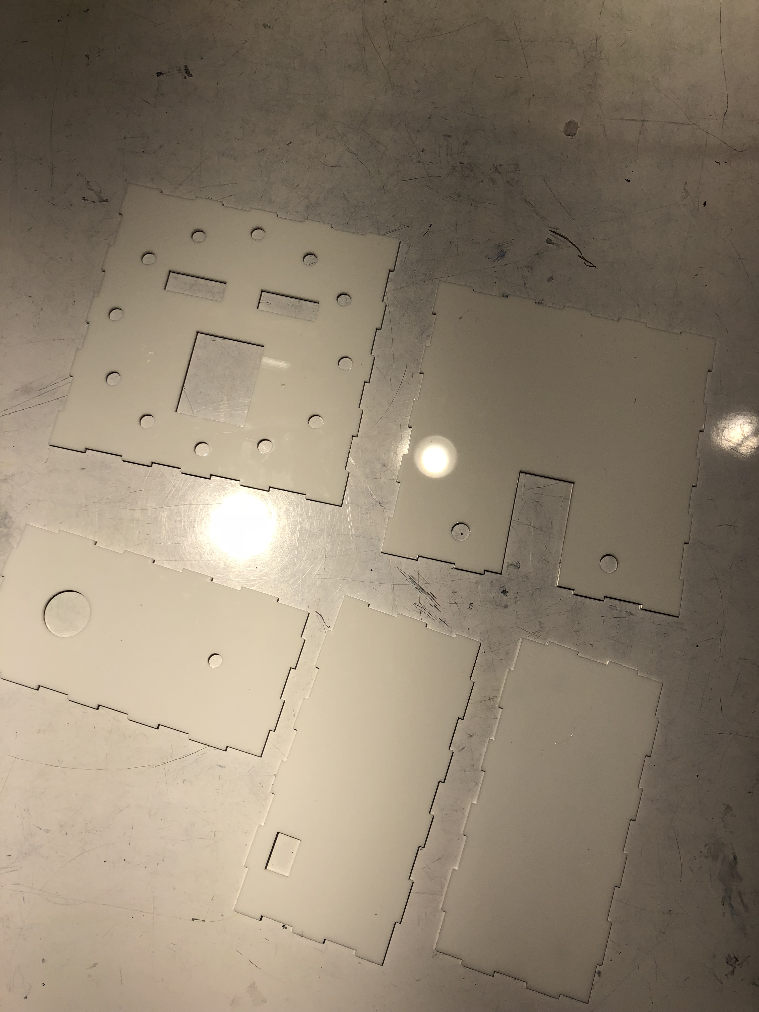
laser cut white acrylics
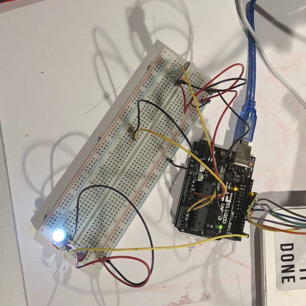
Made sure to have the right code for Neopixel LED, photoresistor and FSR
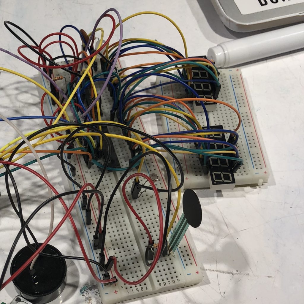
A wrong connection of displays with LED drivers
testing the 12 neopixel LEDs changing colors
Decision Point: Instead of showing the current time and alarm times at the same time, compromise with having a number flash at a time
After hours of debugging and trying to overcome the technical difficulties, I could not have the two times show at the same time, but I could get all four digits to show the same number. With time constraint, I decided to make a compromise by having a number flash at a time.
debugging time displays
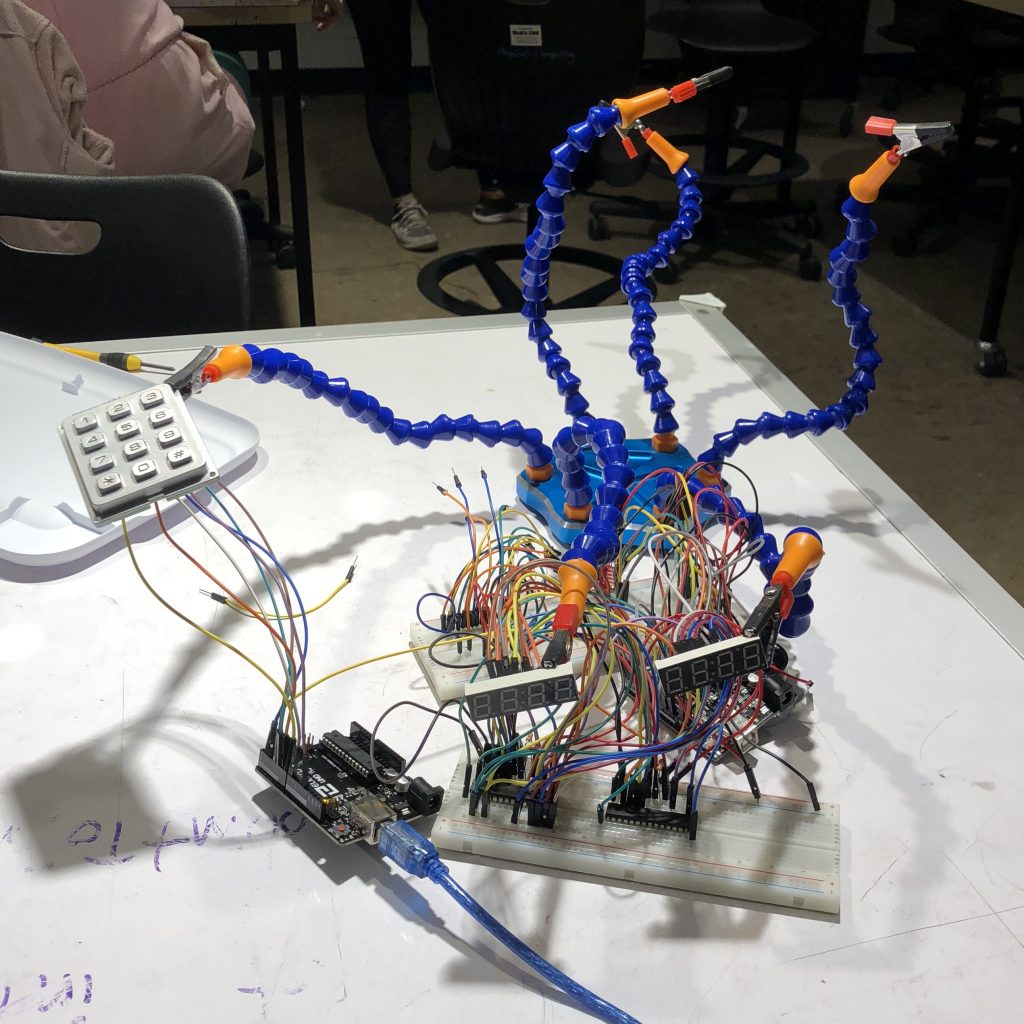
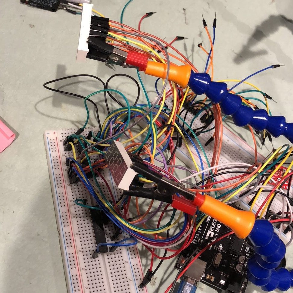
using two arduinos(one on the left and another one behind the breadboard) and debugging the keypad as current time input
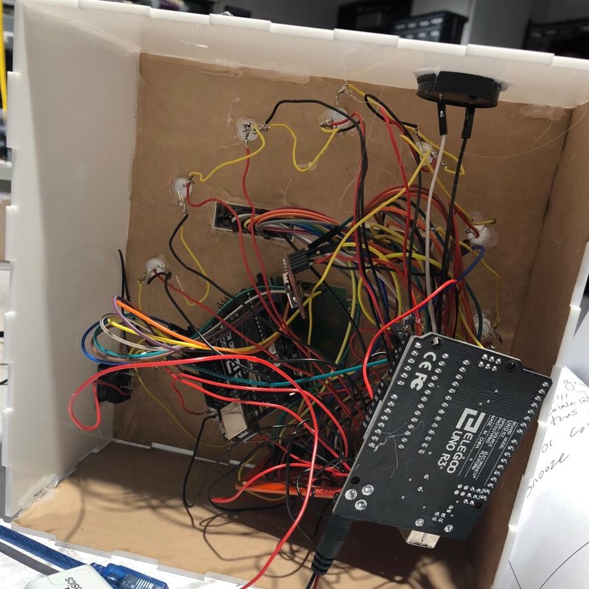
after soldering and lots of wires in the box
Discussion
From the in-class crit, almost everyone commented on the aesthetics. One wrote “GREAT DESIGN, I love the white box” and another one wrote that the “box looks great”. I love how the white acrylic box turned out to be too, and the color and its aesthetics do really match my room. I also received comments pointing out that it is “an ambitious project that required a lot of integration of different components” and the classmate also thinks I might have found full success if I simplified it a little bit. I totally agree, and in fact, this pertains to a lot of my self critique and what I learned from this project. My biggest struggle were the time displays. This could be simply solved with using a LCD display and a lot of time would have been saved, but I was stubborn and did not want to give up the pretty LED displays. Looking back, I should have switched after I discovered that there aren’t any tutorials that are similar to my situations online and should have definitely switched after hours of debugging with Zach and Runchung. In the future, if I run into similar issues again, I should mockup a backup plan before investing so much time in my ideal plan. Another issue I ran into was incompatibilities of libraries. A couple hours before the presentation, I had code ready for LEDs in one file and everything else in another, then I started soldering. I assumed the Neopixel library would not have any conflicts with the other libraries so I made a mistake by not testing the entire system before soldering. This is a big lesson for me on working with hardwares. In the future, I should check libraries compatibilities early in the project. Overall, I’m not really happy with how the project came out considering how much time and effort I put into it, and how everything broke less than two hours before the presentation(when I combined the two files ). Looking back, there are many things that I could have done to avoid all these problems. However, I do think this project is a meaningful lesson to me in so many aspects, technicals, working with time constraints, problem-solving in general, and stop being so stubborn. I do hope to build another iteration of this project and have the alarm clock to be fully functioning with the features I need. I will probably only use one time display with a switch controlling whether the current time or the alarm time is in display(although I do really like the current face design… I might be stubborn again…) As of inputing time, Zach mentioned potentiometer is probably a better way to approach, I will consider it but the keypad is still the one I want to go with, because me personally, I like number enterings a lot more than adjusting numbers with a knob. For the code, I need to find a way to use the neopixels without time interrupters(which I did find a library that claimed to do so but I did not have time to look into it), and actually fabricate the pressure pads.
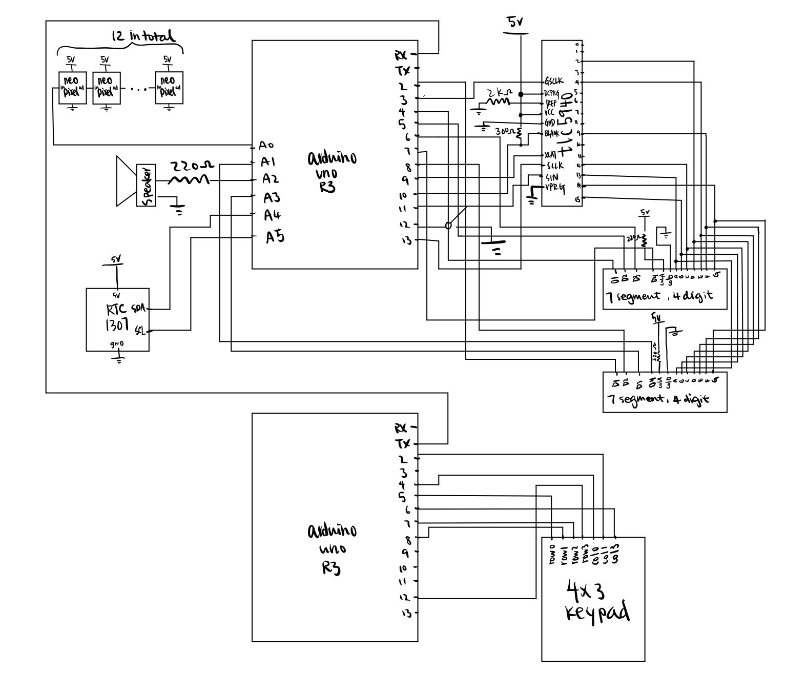
Schematic
Code
main arduino code:
/*
 * Project Title: Alarm Clock That Actually Wakes Me Up
 * Name: Catherine Yu
 * Description: An alarm clock that make noises and lights up when it is the time to wake up
 *              and can be only turned off my jumping on a pressure pad attached to it.
 * Pin mapping: TLC and time display mapping is in variable of SEGMENTS[]
 * Credit: 7Segment Code Table found here https://www.instructables.com/id/Arduino-7-Segment-Clock/
 */
#include <Wire.h>
#include <SparkFunDS1307RTC.h>
#include <Adafruit_NeoPixel.h>
#include "Tlc5940.h"

int checkInterval = 400;
bool lightsOn = false;


//FSR
const int FSRPIN = A0;
const int PRESSURETHRESHOLD;
//SPEAKER
const int SPEAKERPIN = A2;
//BUTTON
const int SWITCHPIN = 12;
//TIME DIPLAY
//pins correspond to pins on TLC
int SEGMENTS[] = {13,15,12,2,4,9,14};
/*const int pinA = 13;
const int pinB = 15;
const int pinC = 12;
const int pinD = 2;'1
const int pinE = 4;
const int pinF = 9;
const int pinG = 14;*/
const int CURRPINS[] = {4,5,6,7};
const int ALARMPINS[] = {2,8,A3,A1};
const byte segCode[10][8] = {
// 7 segment code table
//  a  b  c  d  e  f  g  .
  { 1, 1, 1, 1, 1, 1, 0, 0},  // 0
  { 0, 1, 1, 0, 0, 0, 0, 0},  // 1
  { 1, 1, 0, 1, 1, 0, 1, 0},  // 2
  { 1, 1, 1, 1, 0, 0, 1, 0},  // 3
  { 0, 1, 1, 0, 0, 1, 1, 0},  // 4
  { 1, 0, 1, 1, 0, 1, 1, 0},  // 5
  { 1, 0, 1, 1, 1, 1, 1, 0},  // 6
  { 1, 1, 1, 0, 0, 0, 0, 0},  // 7
  { 1, 1, 1, 1, 1, 1, 1, 0},  // 8
  { 1, 1, 1, 1, 0, 1, 1, 0}   // 9
};
//LED
const int LEDPIN = A0;
const int N_LEDS = 12;
int r;
int g;
int b;
Adafruit_NeoPixel strip = Adafruit_NeoPixel(N_LEDS, LEDPIN, NEO_RGB);

unsigned long lastTime = 0;
unsigned long currTime = 0;

void setup() {
  Serial.begin(9600);
  //RTC
  rtc.begin();
  rtc.setTime(0, 29, 13, 1,1,1,1);
  //TLC
  Tlc.init();
  //FSR
  pinMode(FSRPIN,INPUT); //analog
  //SPEAKER
  pinMode(SPEAKERPIN, OUTPUT); //digital
  //BUTTON
  pinMode(SWITCHPIN,INPUT_PULLUP);
  //TIME DISPLAY
  for(int i = 0; i<4; i++){
    pinMode(CURRPINS[i], OUTPUT);
    pinMode(ALARMPINS[i], OUTPUT);
  }
  //LED
  strip.begin();
  strip.show();
}

void turnOnLEDs() {
    r = random(225);
    g = random(225);
    b = random(225);
    for (int i = 0; i < strip.numPixels(); i++) {
      strip.setPixelColor(i, r, g, b);
    }
    strip.show();
  lightsOn = true;
}

void turnOffLEDs () {
  for (int i = 0; i < strip.numPixels(); i++) {
    strip.setPixelColor(i, 0, 0 , 0);
  }
  strip.show();
  lightsOn = false;
}

//void printTime() {
//  Serial.print(String(rtc.hour()) + ":"); // Print hour
//  if (rtc.minute() < 10)
//    Serial.print('0'); // Print leading '0' for minute
//  Serial.print(String(rtc.minute()) + ":"); // Print minute
//  if (rtc.second() < 10)
//    Serial.print('0'); // Print leading '0' for second
//  Serial.println(String(rtc.second())); // Print second
//}

void setDigitPins(bool current, int high){
  for (int i=0; i<4; i++){
    if(i==high){
      if(current){
        digitalWrite(CURRPINS[i], HIGH);
        digitalWrite(ALARMPINS[i], LOW);
      }
      else{
        digitalWrite(CURRPINS[i], LOW);
        digitalWrite(ALARMPINS[i], HIGH);
      }
    }
    else{
      digitalWrite(CURRPINS[i], LOW);
      digitalWrite(ALARMPINS[i], LOW);
    }
  }
}
void displayNumber(int digit, int num, bool current){
  Tlc.clear();
  Serial.println(num);
  setDigitPins(current,digit-1);
  for (int i = 0; i<7; i++){
    if (segCode[num][i] == 1){
      Tlc.set(SEGMENTS[i],4000);
    }
    else{
      Tlc.set(SEGMENTS[i],0);
    }
  }
  Tlc.update();
}

int getCurr1(int h){
  if(h<10){
    return 0;
  }
  return h/10;
}

int getCurr2(int h){
  return h%10;
}

int getCurr3(int m){
  if(m<10){
    return 0;
  }
  return m/10;
}

int getCurr4(int m){
  return m%10;
}

void updateDigits(int digs[], int d1, int d2, int d3, int d4){
  digs[0] = d1;
  digs[1] = d2;
  digs[2] = d3;
  digs[3] = d4;
}


int dig = 1;
int alarmDigs[] = {0,0,0,0};
int currDigs[] = {0,0,0,0};
bool triggered  = false;
bool pressured = false;
bool button = true;
void loop() {
  rtc.update();
  currTime = millis();
  int hour = rtc.getHour();
  int minute = rtc.getMinute();
//  int hour = 2;
//  int minute = 35;
  //update current time
//  updateDigits(currDigs,getCurr1(hour),getCurr2(hour),getCurr3(minute),getCurr4(minute));
  currDigs[0] = 0;
  currDigs[1] = 9;
  currDigs[2] = 3;
  currDigs[3] = 5;
  //update alarm time when key pressed
  if (Serial.available() > 0) {
    Serial.println("LOOK!!");
    int val =Serial.parseInt();
    Serial.println(val);
    updateDigits(alarmDigs,alarmDigs[1],alarmDigs[2],alarmDigs[3],val);
  }
  if (currTime - lastTime >= checkInterval) {
    turnOnLEDs();
    lastTime = currTime;
    switch(dig){
      case 1:
        displayNumber(1,currDigs[0], true);
        dig+=1;
        break;
      case 2:
        displayNumber(2,currDigs[1], true);
        dig+=1;
        break;
      case 3:
        displayNumber(3,currDigs[2], true);
        dig+=1;
        break;
      case 4:
        displayNumber(4,currDigs[3], true);
        dig+=1;
        break;
      case 5:
        displayNumber(1,alarmDigs[0], false);
        dig+=1;
        break;
      case 6:
        displayNumber(2,alarmDigs[1], false);
        dig+=1;
        break;
      case 7:
        displayNumber(3,alarmDigs[2], false);
        dig+=1;
        break;
      case 8:
        displayNumber(4,alarmDigs[3], false);
        dig=1;
        break;
    }
    if(alarmDigs[0]==currDigs[0] && alarmDigs[1]==currDigs[1] && alarmDigs[2]==currDigs[2] && alarmDigs[3]==currDigs[3]){
      triggered = true;
    }
    if(triggered && !pressured){
      turnOnLEDs();
      //turnOnSpeaker
      tone(SPEAKERPIN, 1000);
    }
    if(triggered && !pressured){
      triggered = false;
      pressured = false;
      turnOffLEDs();
    }
    if (digitalRead(SWITCHPIN) == LOW){
      turnOnLEDs();
    }
    else{
      turnOffLEDs();
      Serial.println("high");
    }
  }

}
arduino that sends keypad signals code:
#include <Keypad.h>

//keypad
const byte Rows= 4;
const byte Cols= 3;
char keys[Rows][Cols]=
{
{'1', '2', '3'},
{'4', '5', '6'},
{'7', '8', '9'},
{'*', '0', '#'}
};
byte rowPins[Rows]= {5,8,7,12}; //Rows 0 to 3
byte colPins[Cols]= {4,2,6}; //Columns 0 to 2

Keypad kpd = Keypad( makeKeymap(keys), rowPins, colPins, Rows, Cols );

void setup() {
  Serial.begin(9600);
}
int val = 1;
void loop() {
  char key = kpd.getKey();
  if(key && key != '*' && key != '#')  // Check for a valid key.
  {
    Serial.write(key);
  }
}
Leave a Reply
You must be logged in to post a comment.