For this project, our group of three were tasked with creating a device that would help make the life of our older friend, Jim (as he prefers to go by), better. Though we’re limited by what we’ve learned so far, we were excited to face this task on and to help make something that would survive past the end of this class that would benefit someone else. From our initial first meeting, it is clear to see that the device that would benefit Jim the most would be a device to make sure he doesn’t forget what he need when he leaves the house. We also have another post highlighting what occurred during the first meeting here as well as this post of where our prototype was at about three weeks ago.
WHAT WE BUILT
Description
Our project is a box that is to be installed by Jim’s front door that contains a screen that will display Jim’s items of the day and a motion sensor that triggers the device when he approaches the door. The Google API parses through Jim’s Google Calendar to identify a list of common events or take a list of items from the description of non-common events to display in a list format on his door. Whenever he walks approximately 3 meters by the door, the motion sensor will trip, turning on the display that will remind him to make sure he has all the items he needs for the day.
Final Photographs
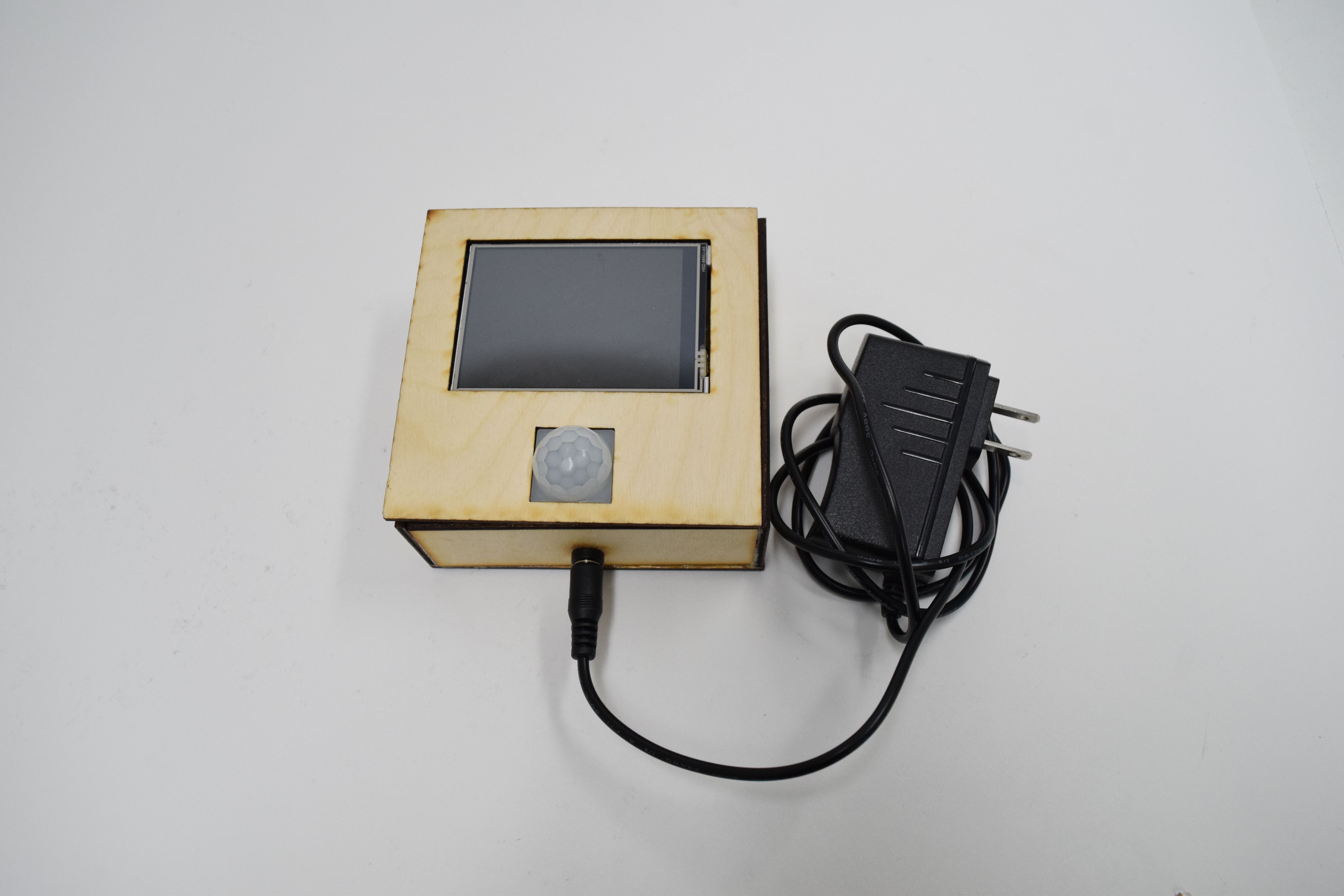
Overall Content Photo
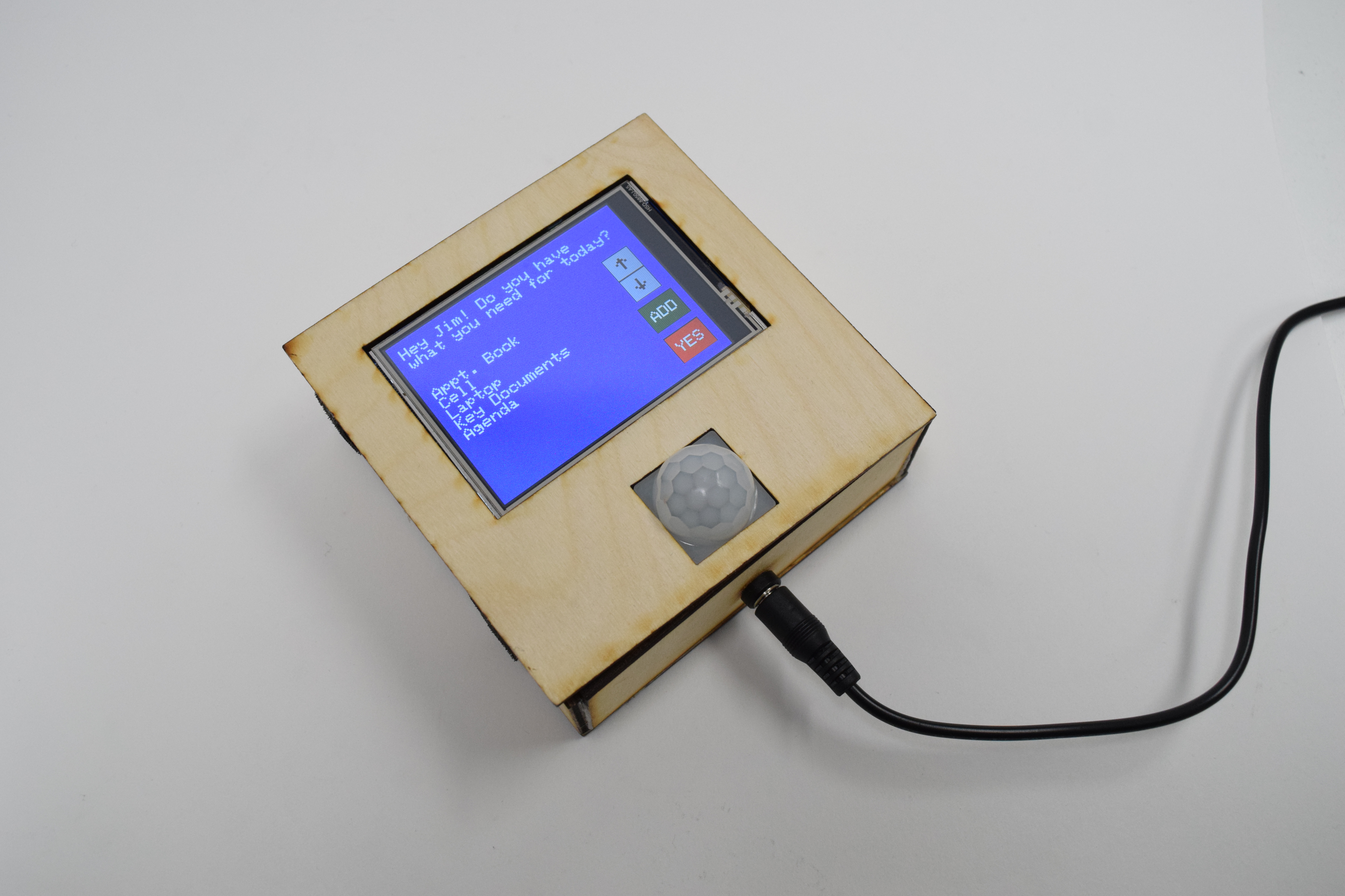
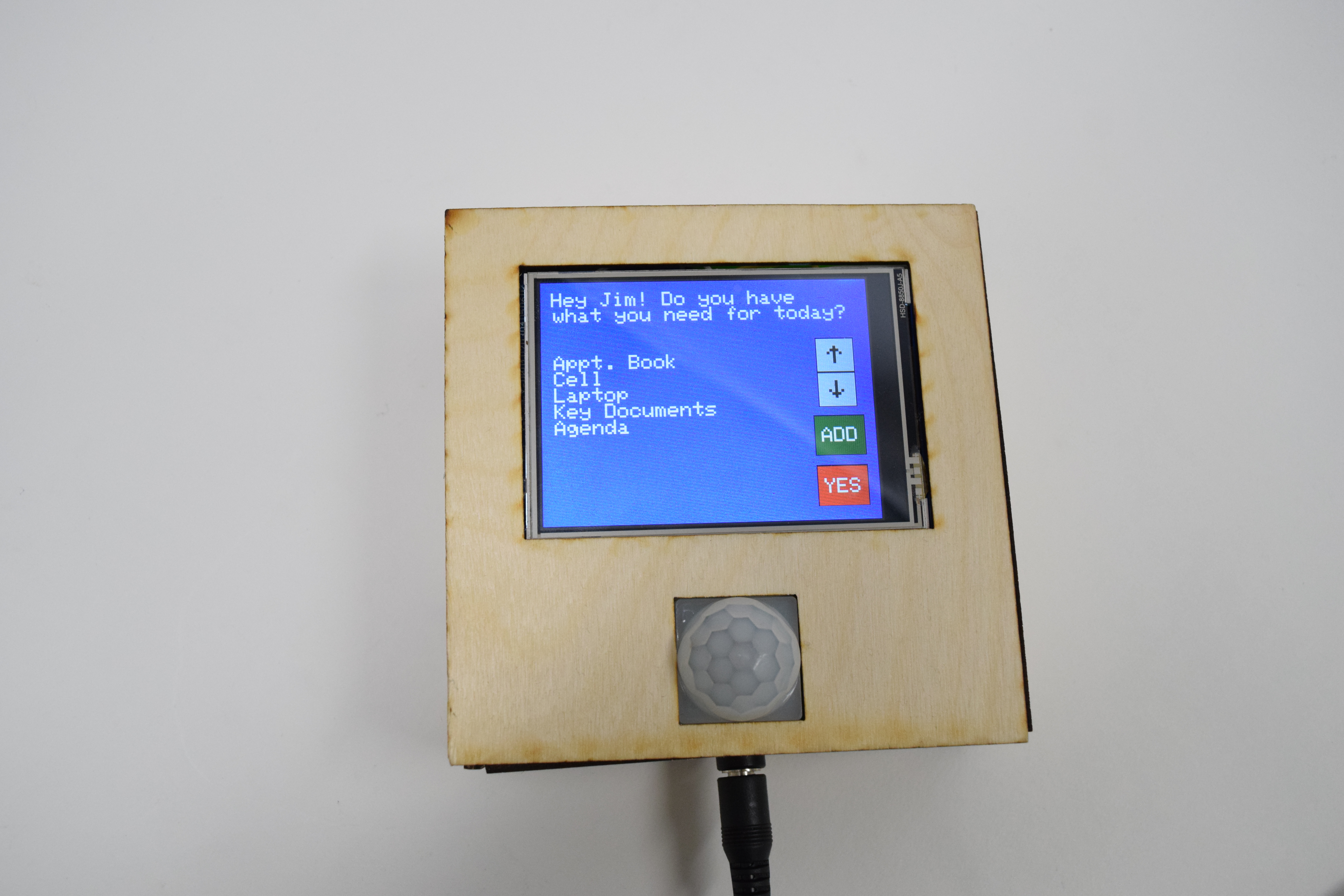
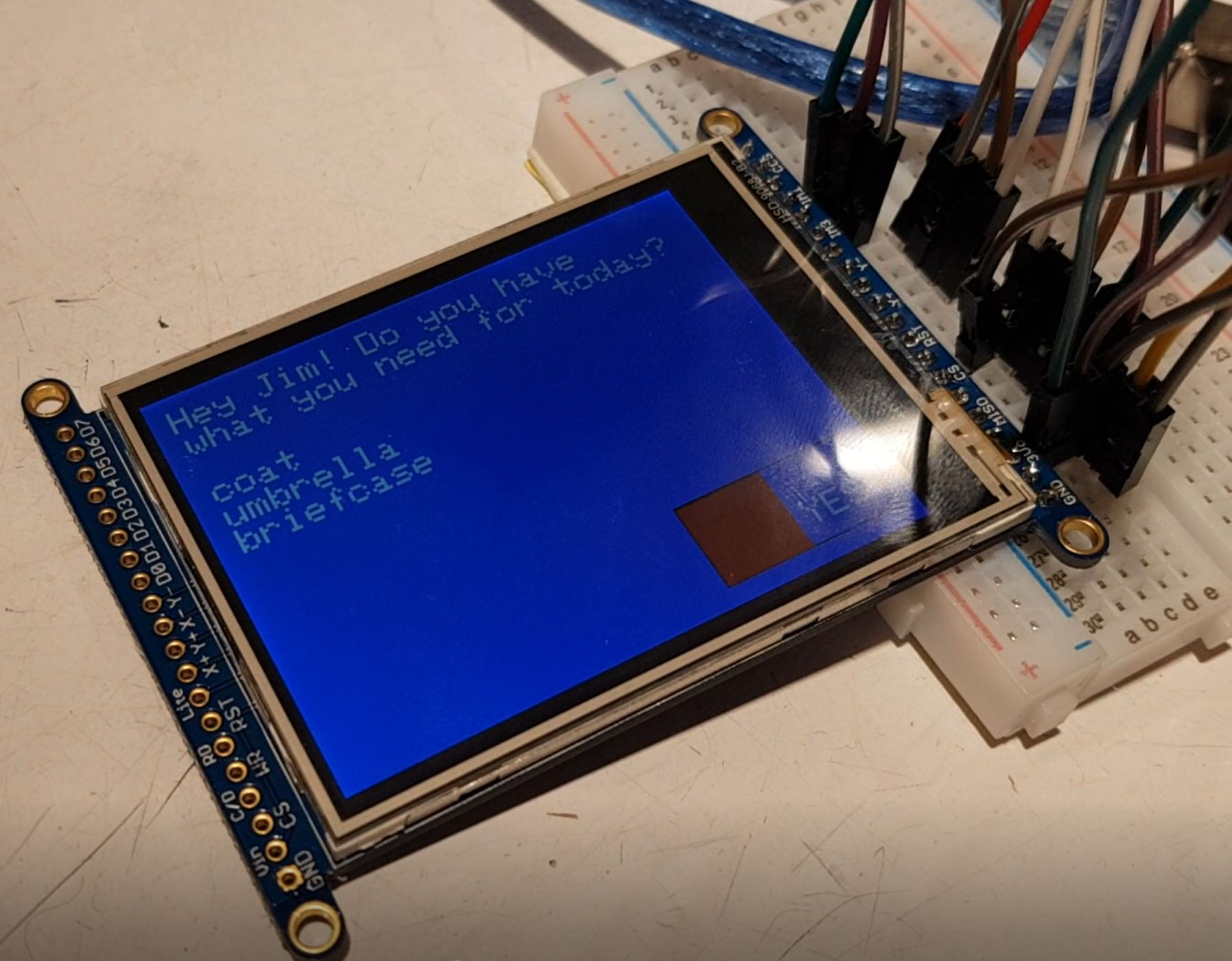
Standard opening screen
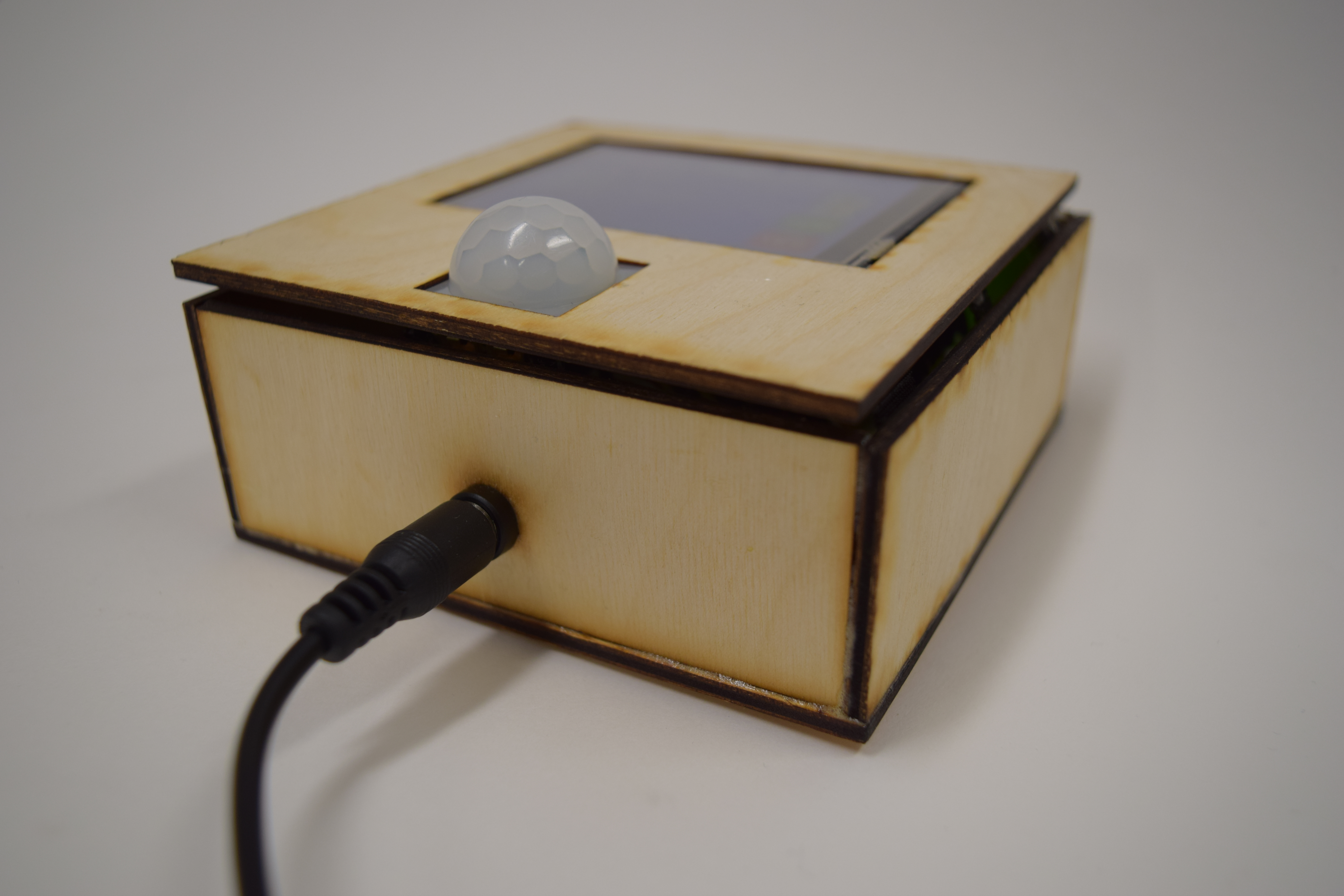
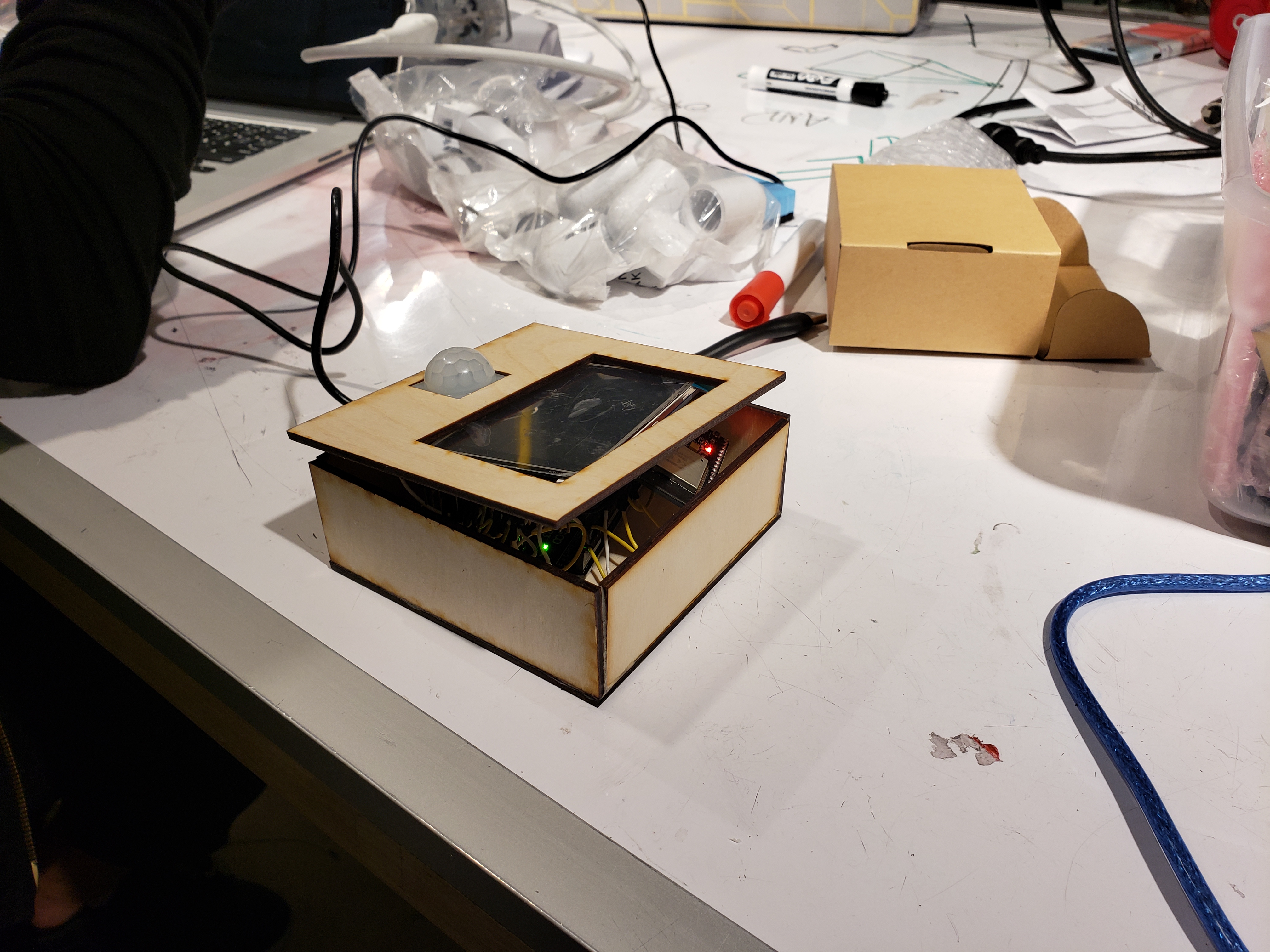
Barrel jack power and ground connection at the base of the box with motion sensor clearly visible
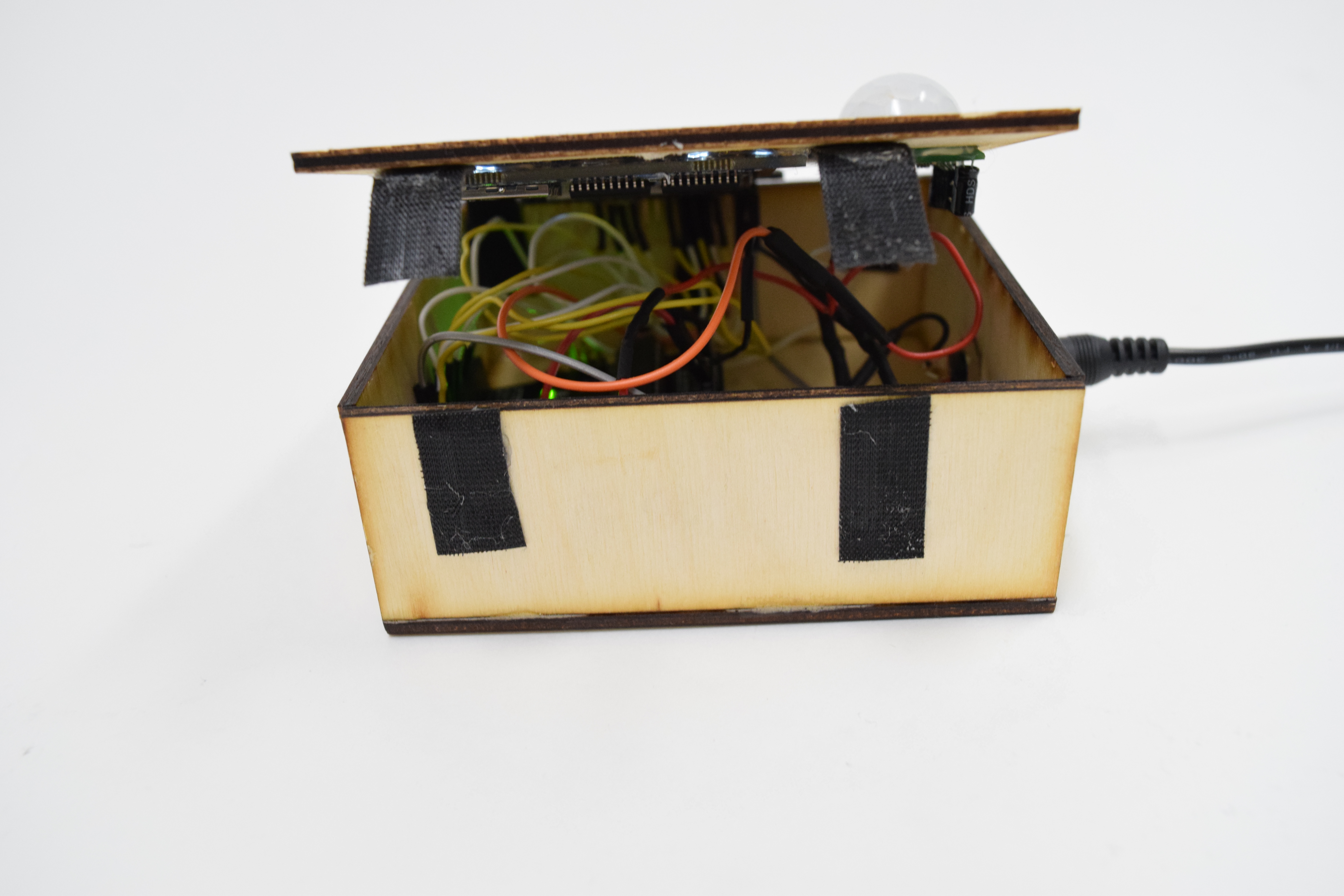
Temporary velcro closing mechanism
Items list screen(1/3)
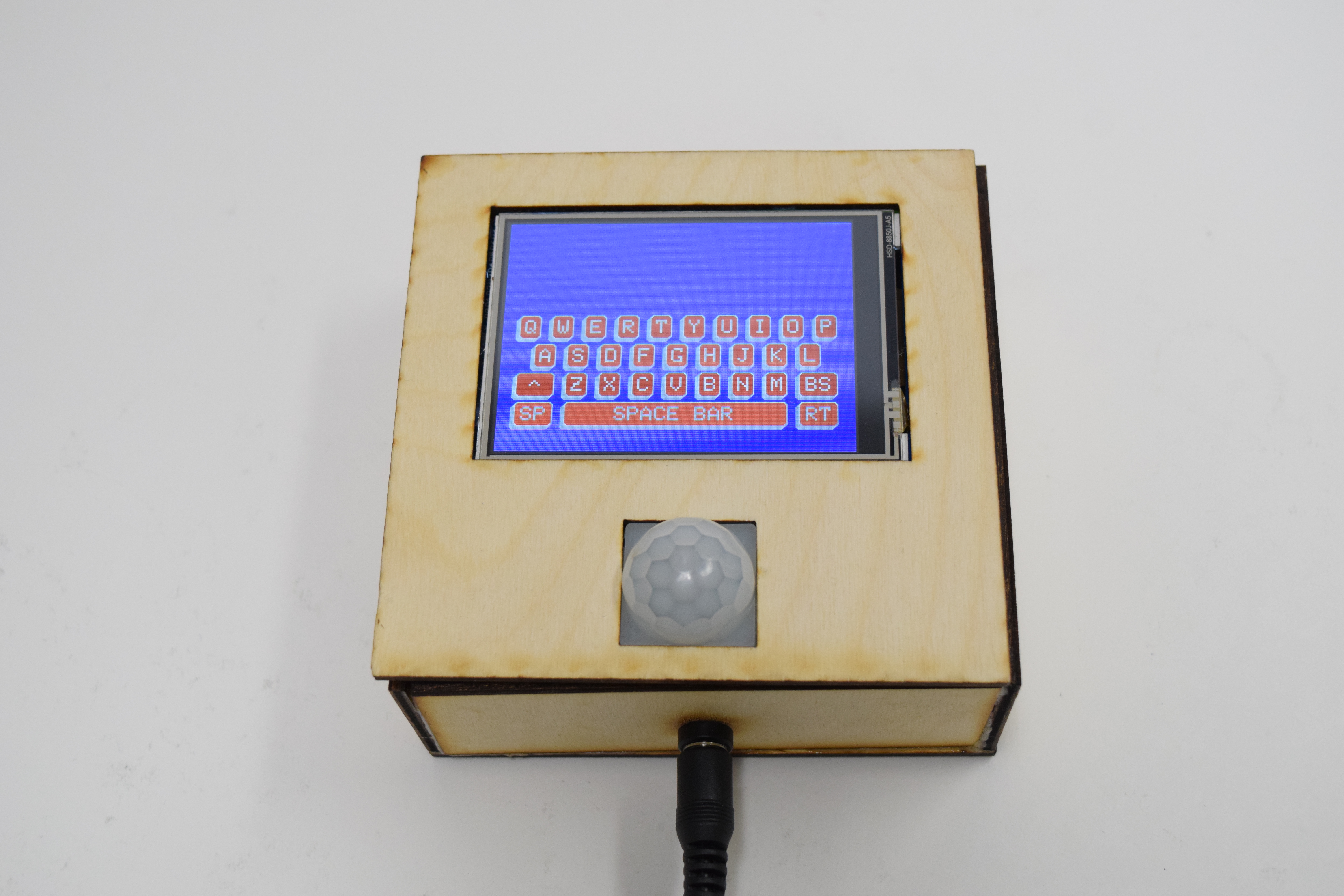
Keyboard screen (2/3)
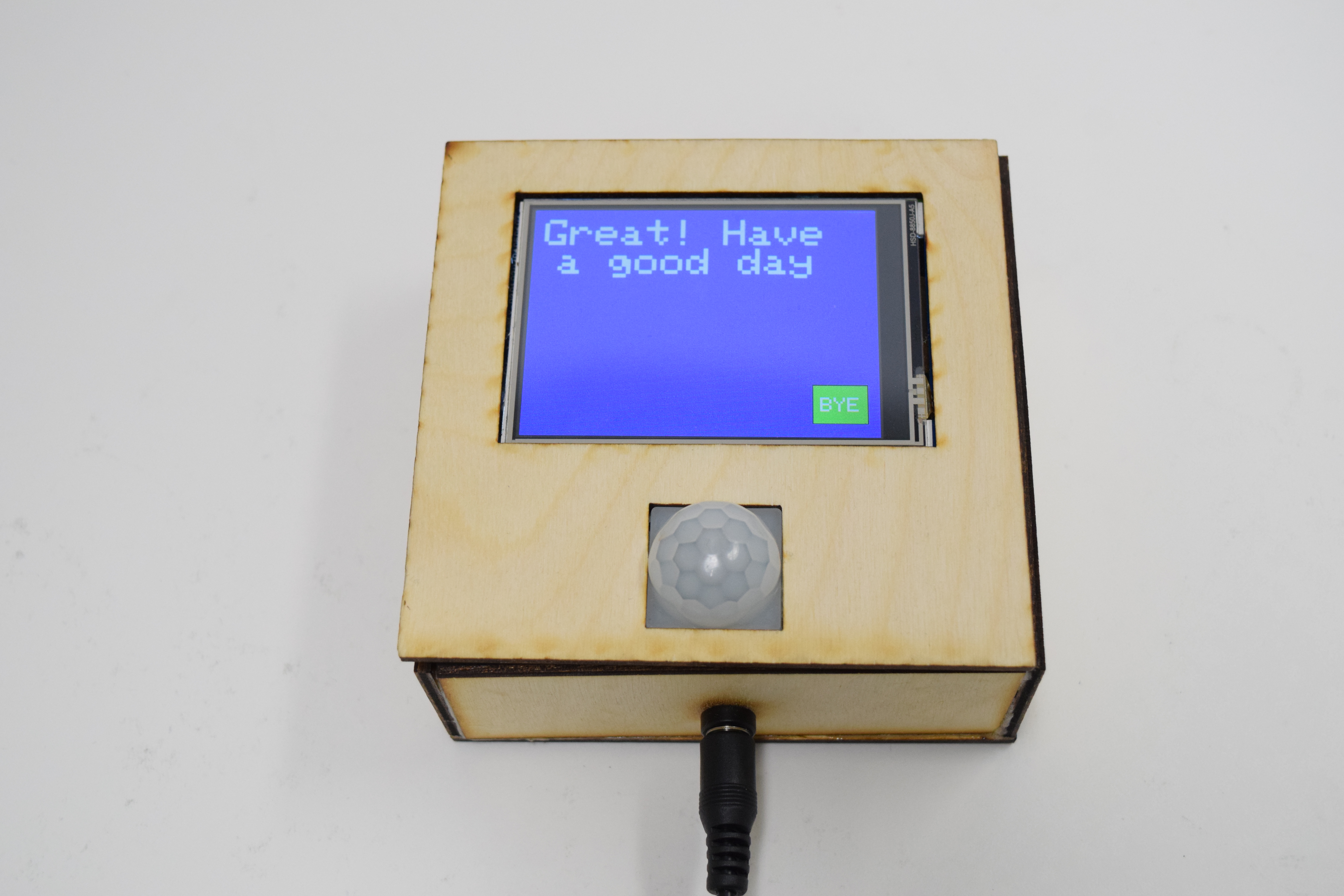
Goodbye screen (1/3)
Narrated Sketch of the Intended Use
Every morning, Jim wakes up to a busy day filled with community activities and long board meetings. Those days often require Jim to bring with him many important supplies, without which his day is not as productive. Often, Jim makes note of the things he needs in his Google Calendar, but that is often in a place that is not as easily accessible to him when he is rushing out the door. Imagine this scenario: Jim is walking out the door in the morning, hoping he remembers everything he needs for the day. Just then, a motion detector by the door detects his presence, and, in response, an LED touchscreen lights up, asking Jim if he has everything he needs for the day based on the entries in his calendar. If the answer is yes, then Jim touches the on-screen button to indicate as such, and off he goes, day’s supplies in tow. This is Jim’s daily reminder box helping make his life easier and more productive, one notification at a time.
HOW WE GOT HERE
Our original idea was to have the ESP connect to a server that parses data from Google API to interpret Jim’s calendar for the day. Then the items for those events would be communicated back to the ESP to be displayed in the form of a checklist on the TFT Display as a reminder when he leaves the house.
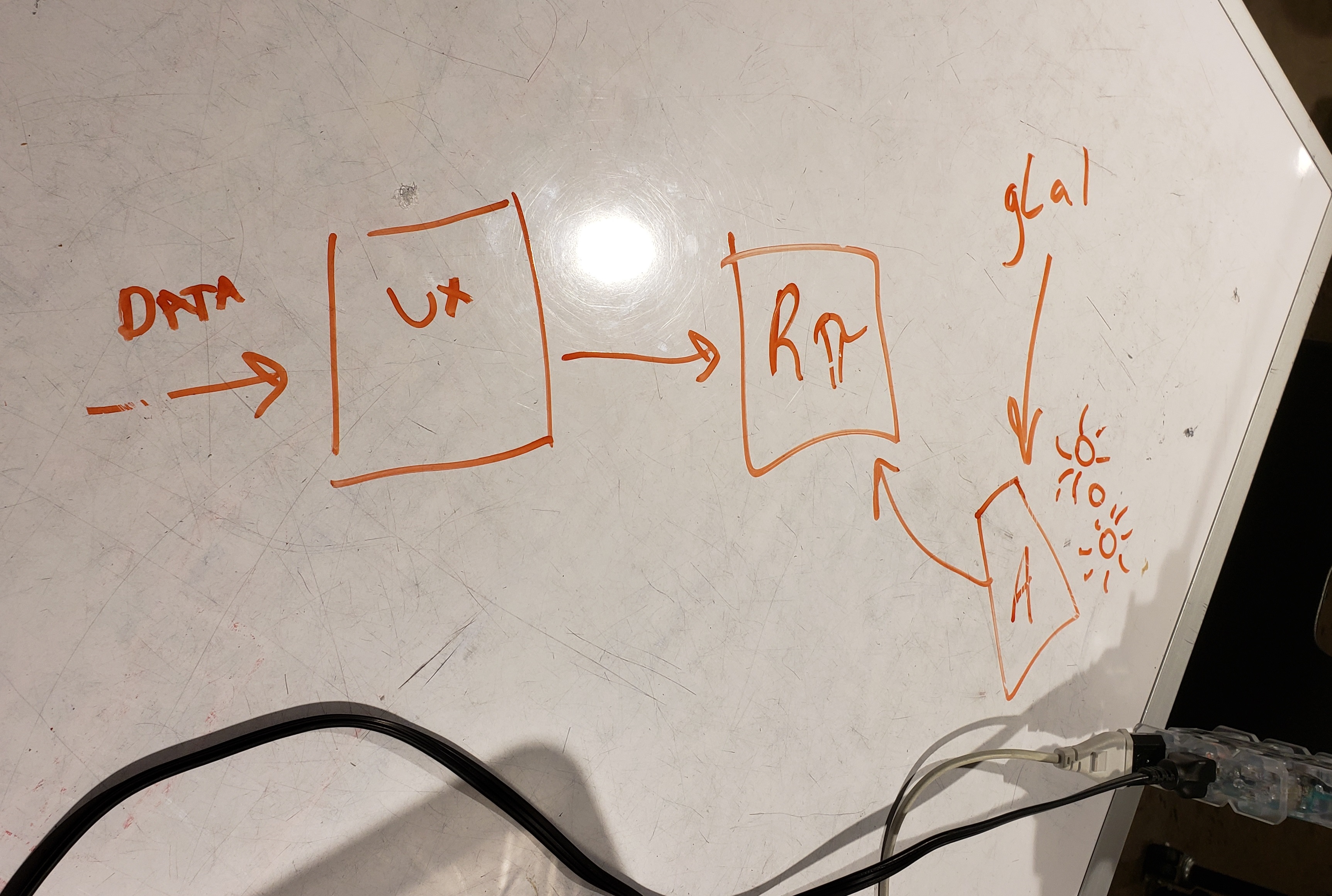
Sketch of one of the earliest planning diagrams when the Arduino was incorporated
Decided not to set up server. We ended up getting recommended to avoid setting up a server, however, because it would have been really difficult and cost money to maintain. Instead we redesigned the system to parse all data locally and on-premise, which had the trade-off of taking up significantly more memory on the ESP32, out IoT chip.
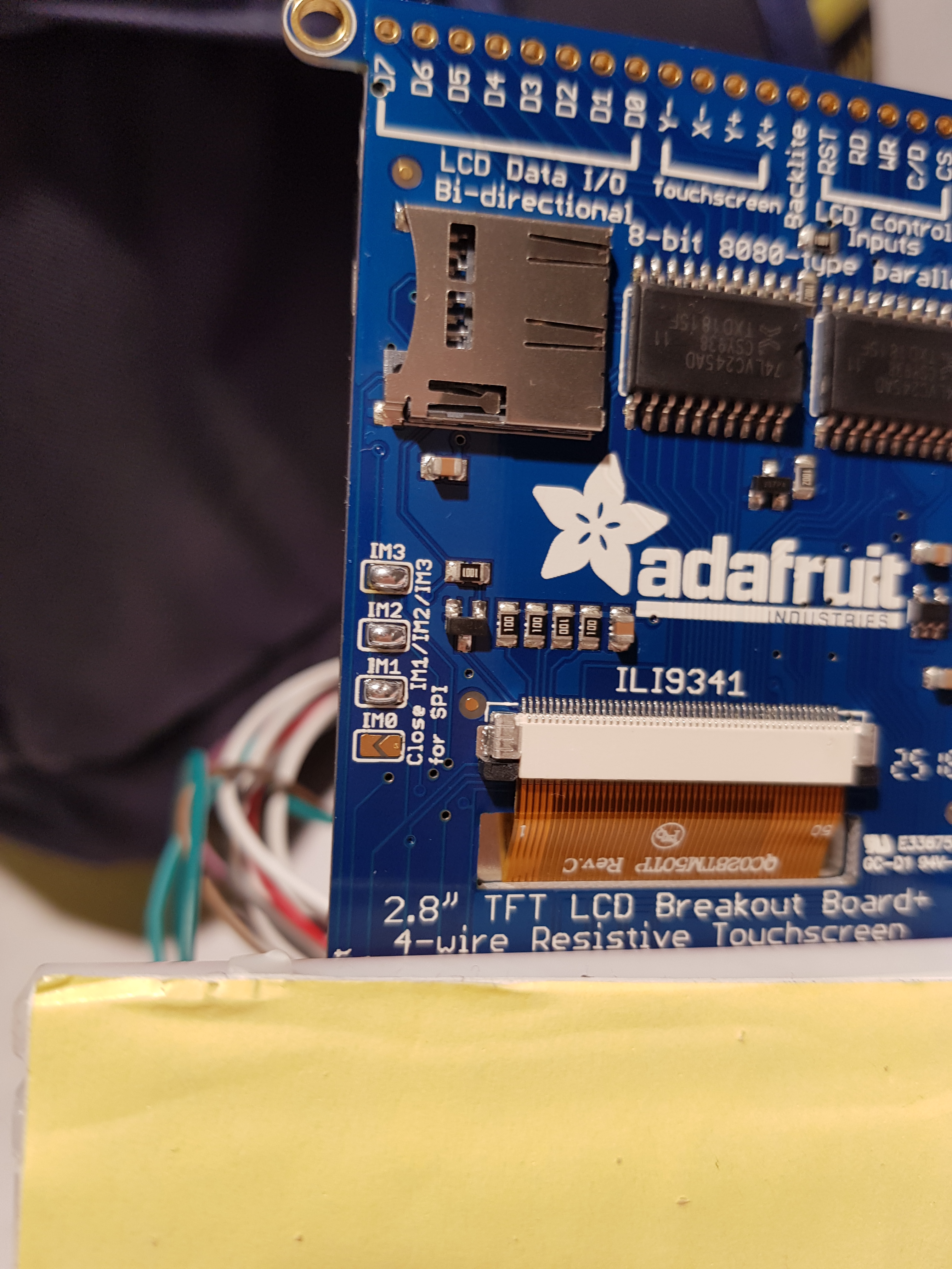
Ordering a second TFT Display. The next part of the process was to adapt the Adafruit ILI9341 library to do exactly what we needed on the touchscreen display. After the prototype we ordered a slightly bigger screen based off the request of Jim. This served to be useful in the long run since it allowed two people to work n the screens simultaneously and independently. Catherine’s biggest problem was getting the touch to respond properly either due to wearing down the screen or something wrong with the smaller screen.
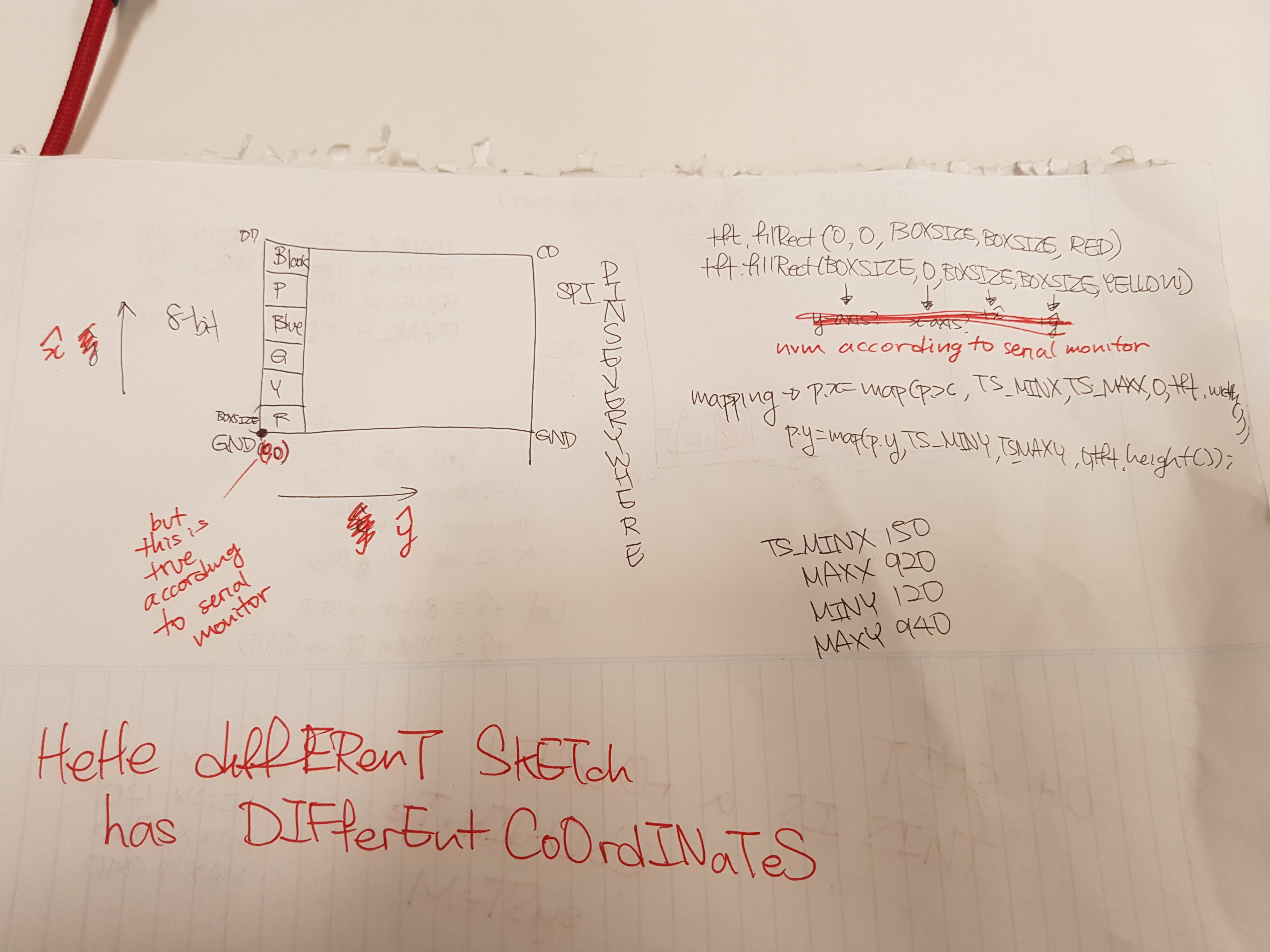
Attempt#1 for coordinates and basic code with display
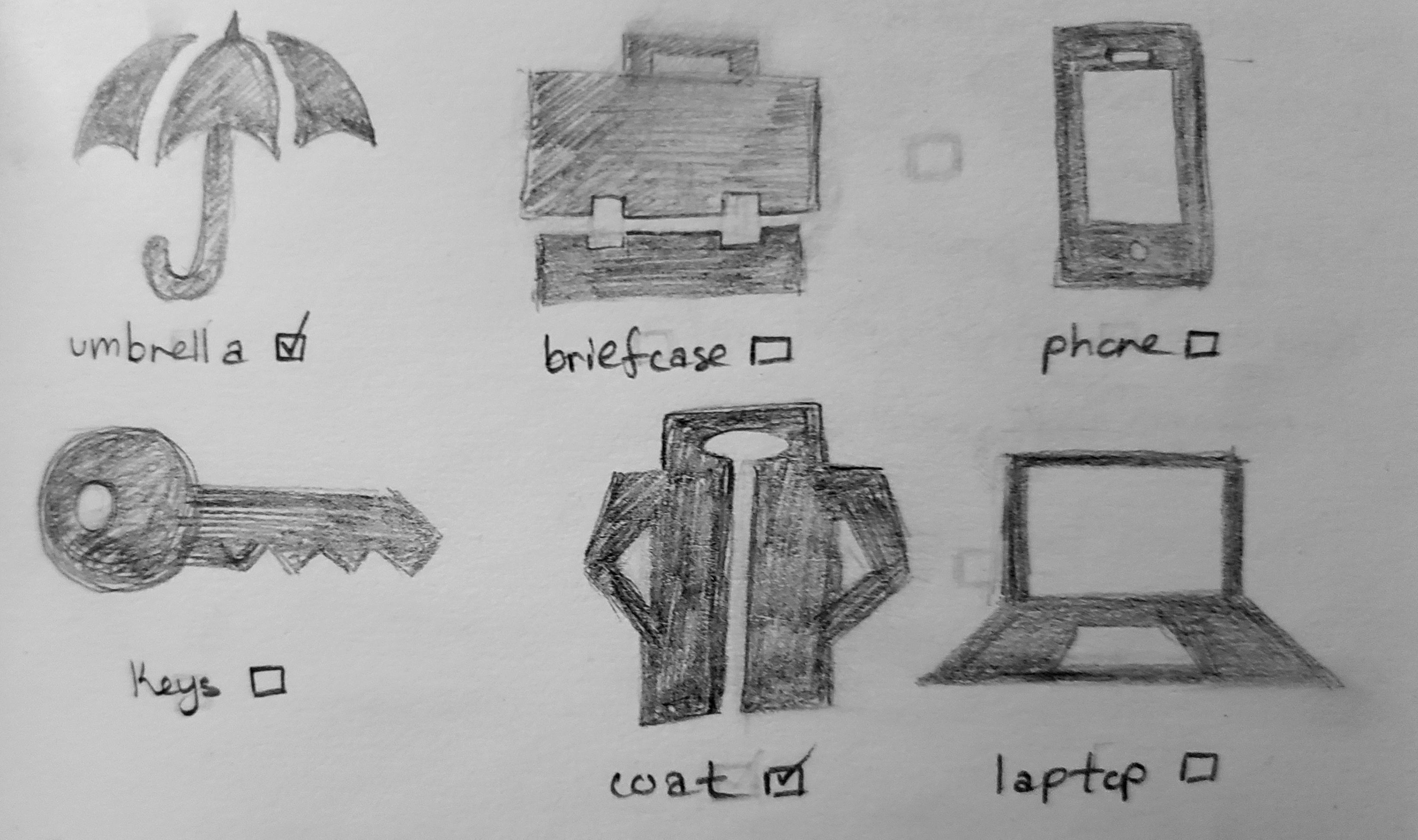
While she tinkered with the bigger screen, Lexi experimented with displaying icons to improve visibility of Jim’s items.
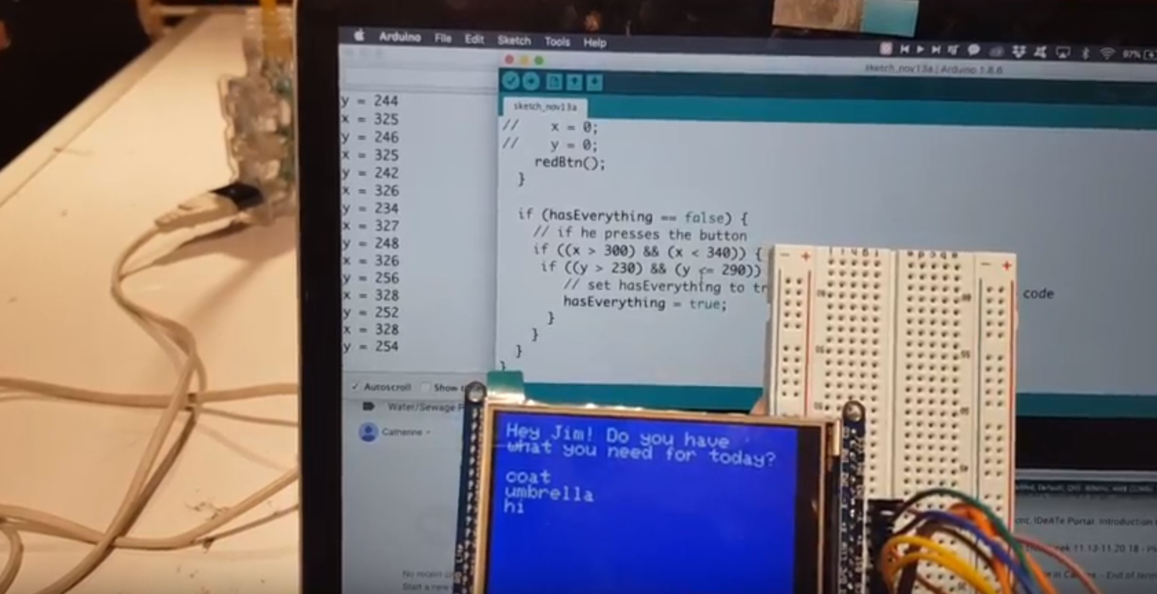
Updating the screen based on input from the Serial Monitor
Initially and for demo purposes, we set up the touchscreen to behave like the Google API by pulling data from the Serial monitor. When the screen would sense something written into the Serial monitor, it would perform a Serial.read() to pull that data and print it on the touchscreen.
Serial and display communicating
Getting a keyboard on the display through the ESP. We discovered that there were many problems implementing touch onto the TFT display when connected to the ESP.
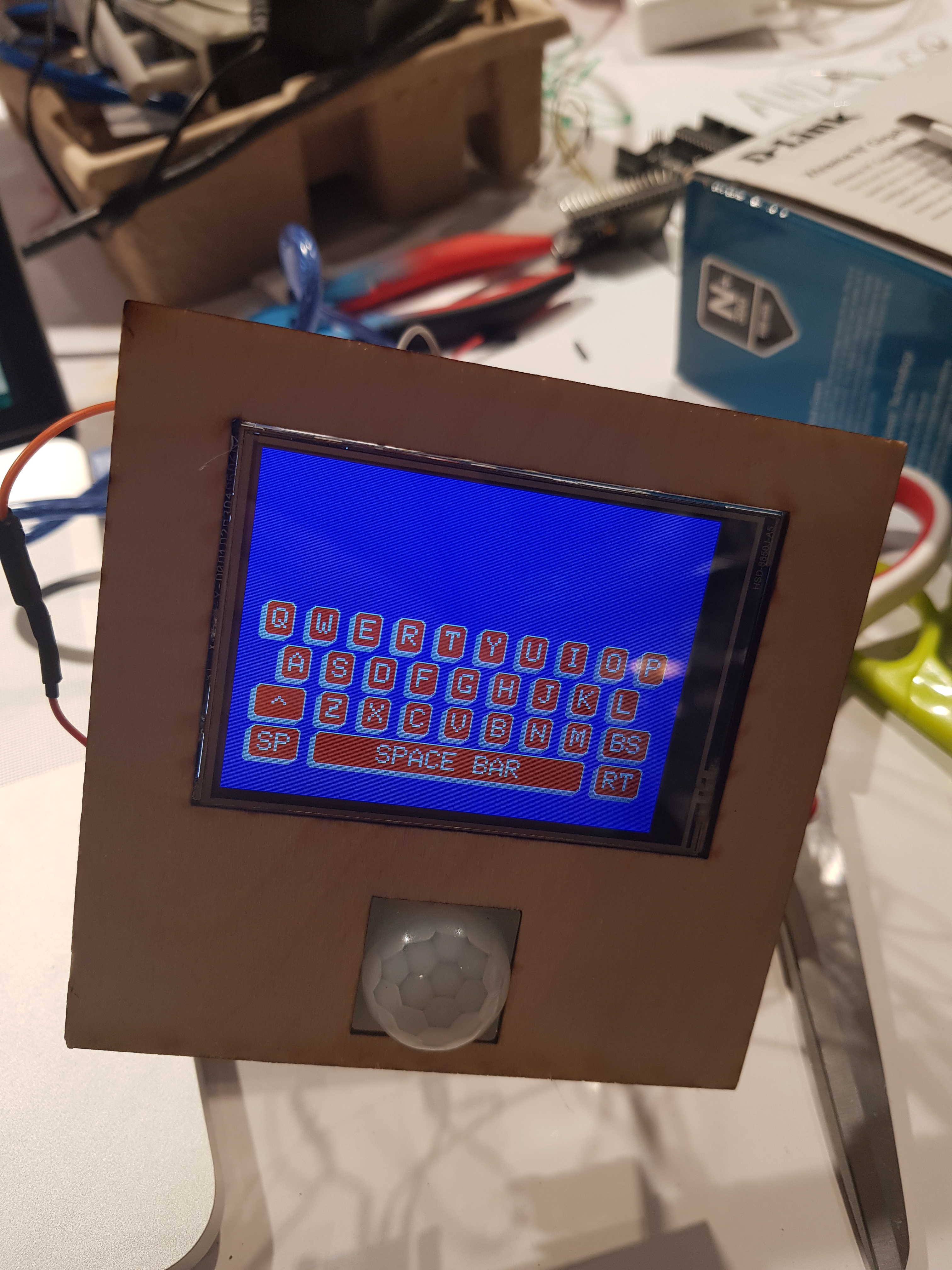
Tft display with touchscreen keyboard
We needed to have the keyboard so that Jim could input the verification required to access his wifi once he moved houses. This is because the ESP will not be able to communicate with anything else in the system until it is connected to the WiFi. Ultimately we decided that it’d be better to prioritize the touchscreen keyboard and connected the display to the Arduino which would in turn communicate with the ESP through the RX and TX pins. This also resulted in the scrapping of the icons due the example pictureEmbeded only working with an ESP.
Icon conversion issues. The first problem with the icon displaying was that it took Lexi a week to realize the example code, Adafruit ILI9341’s pictureEmbeded, wasn’t designed to work on Arduino Unos, which she had been testing with. This code doesn’t work with an Arduino, however, so we had to scrap it. Even before we scrapped it though, we were running into the issue that the image converter Lexi was using to the transfer the pixel measurements of the icon into hex codes kept returning values of at least 15,500 values. uint16_t is able to store at most 14,000 values and experimenting with image sizing and various settings would either increase the number of values or have it stay the same. We ended up ditching the entire idea before she had to attempt to find another image converting method.
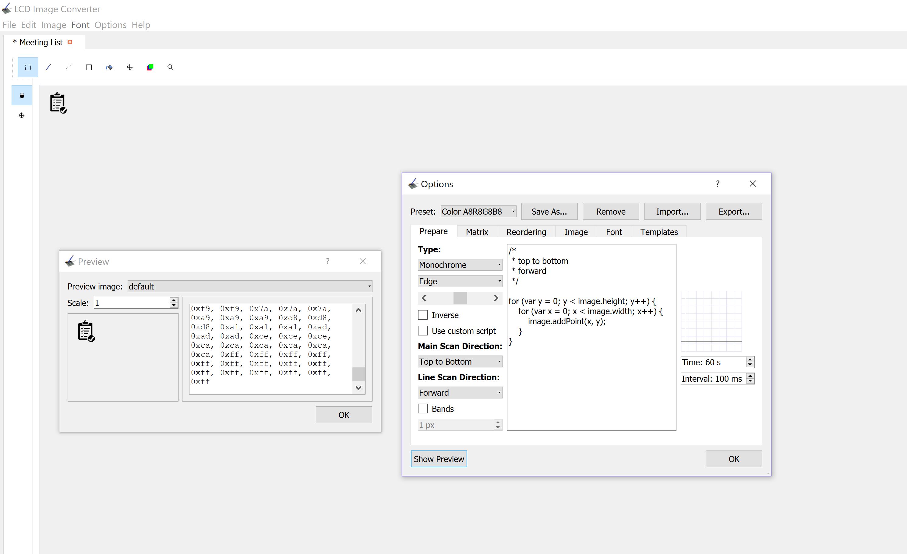
Image converted into hex codes
Router to connect ESP to Wifi. It would have been useful to discover earlier that a router could be set up to bypass the issue of the ESP connecting to CMU-SECURE. This is due to the way the ESP handles the wifi verification. Since it is much harder to connect to WEP-Enterprise networks, testing anything on campus was impossible. It would have been nice to realize that a router was an option a few days before we did. At that point, there had already been a few days of Catherine testing various bits of code that Sana wrote and implementing at Catherine’s house due to Sana using the school wifi at home.
Memory Problems with the ESP. The ESP32, despite being a chip that can access the internet, holds a very small amount of memory. Accessing the Google Calendar API returned an extremely long string of characters, which was large enough to cause overflow in memory. As a result, the ESP32 turned out being the wrong device for us to use for this project.
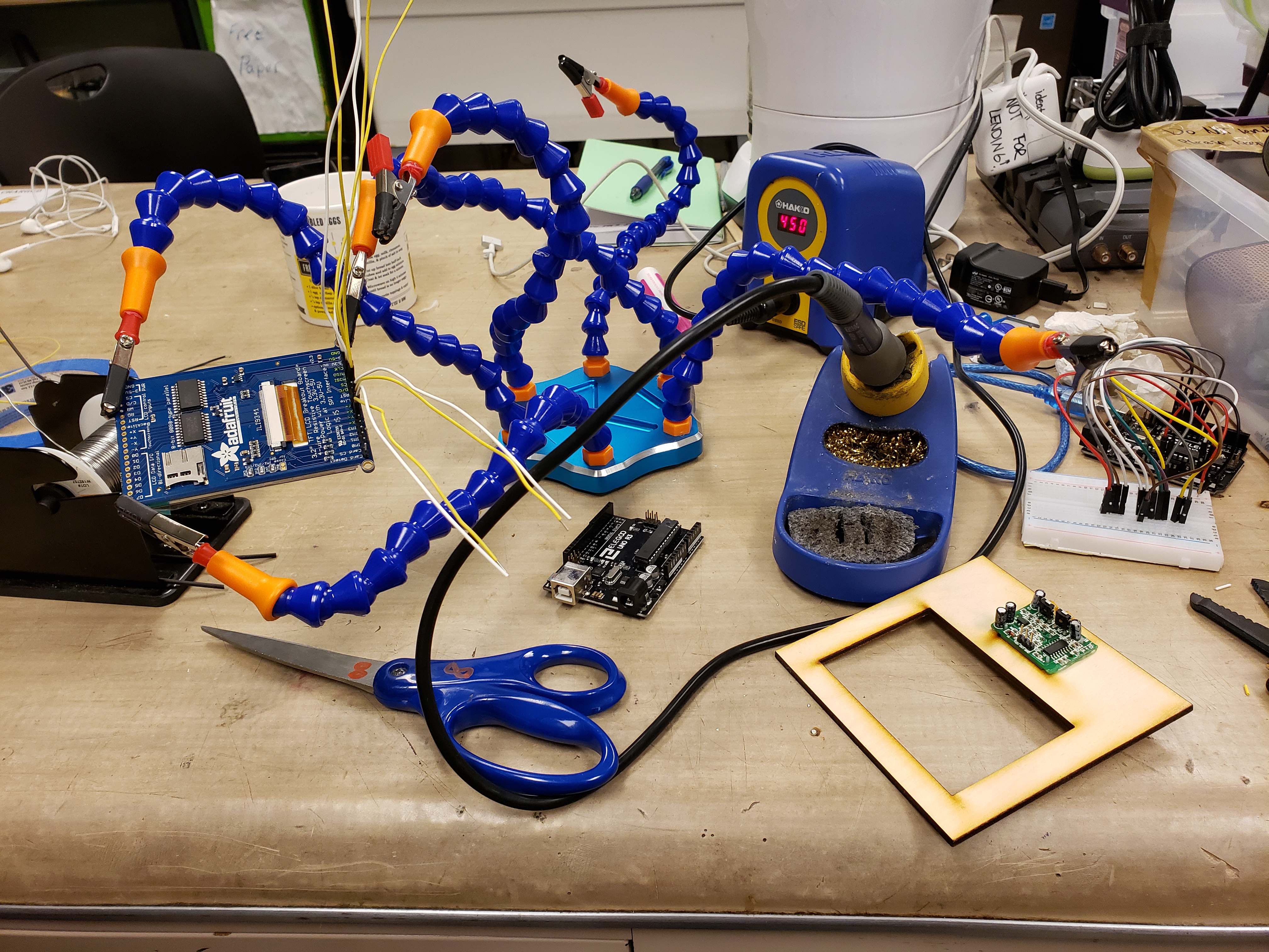
Soldering all the wires together to make the connections inside the box more durable
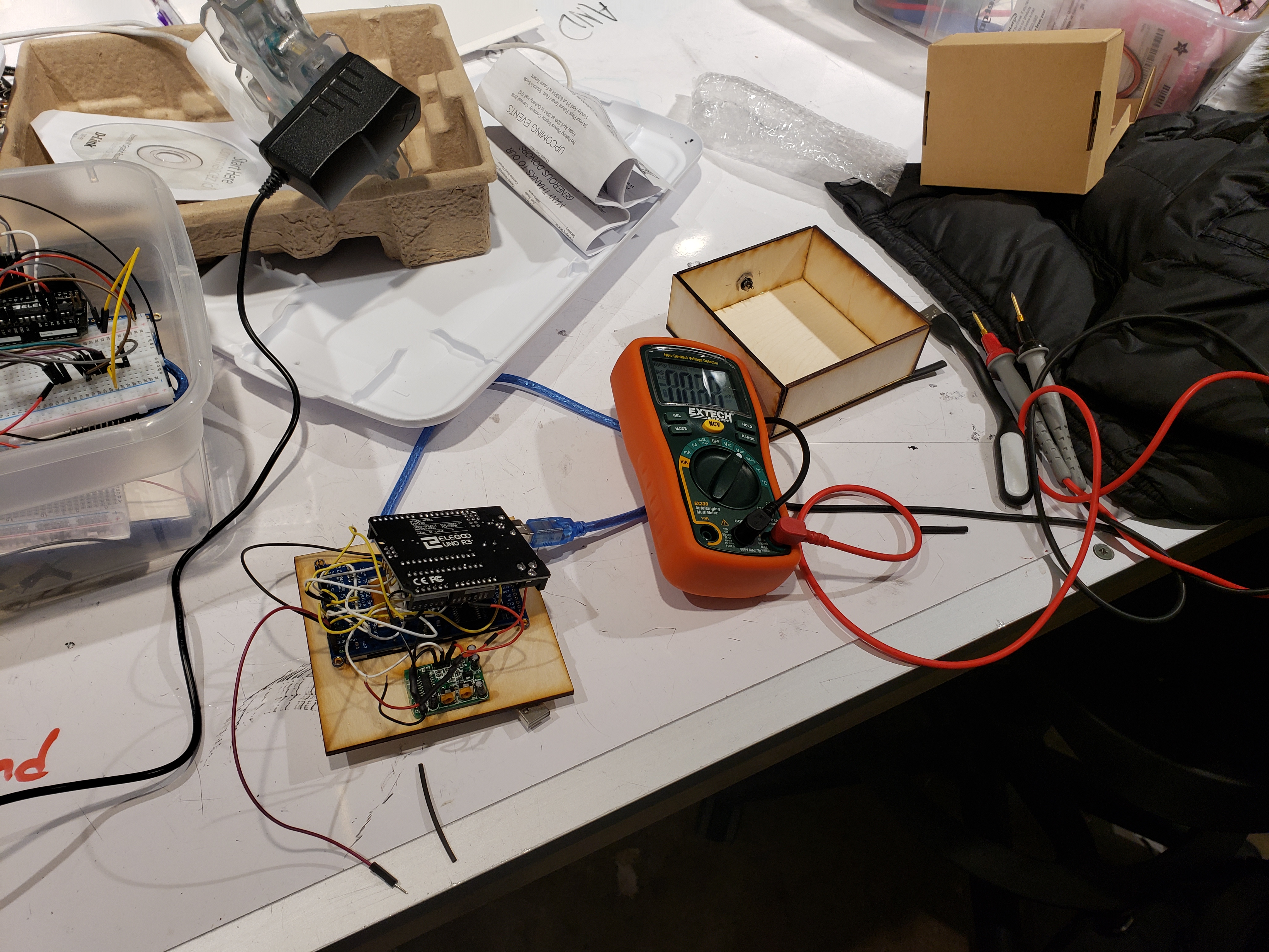
Testing the power and ground side of the DC Jack using the multimeter
Velcro-ing the box closed. Originally we were thinking about gluing the box closed with everything inside it.
The box post-soldering pre-velcroing
Due to the impermanent nature of our box at the time of the demo, we decided to velcro the box closed. This was because velcro is the easiest way of closing the box without prior planning and worked pretty well for what we needed. We realized by doing this that it could actually benefit the box for it to have the option of opening in case anything goes wrong/something gets jostled when Jim moves between houses. As a result, we decided to add latches and a hinge to attach to the final one but didn’t manage to get them in time for documentation.
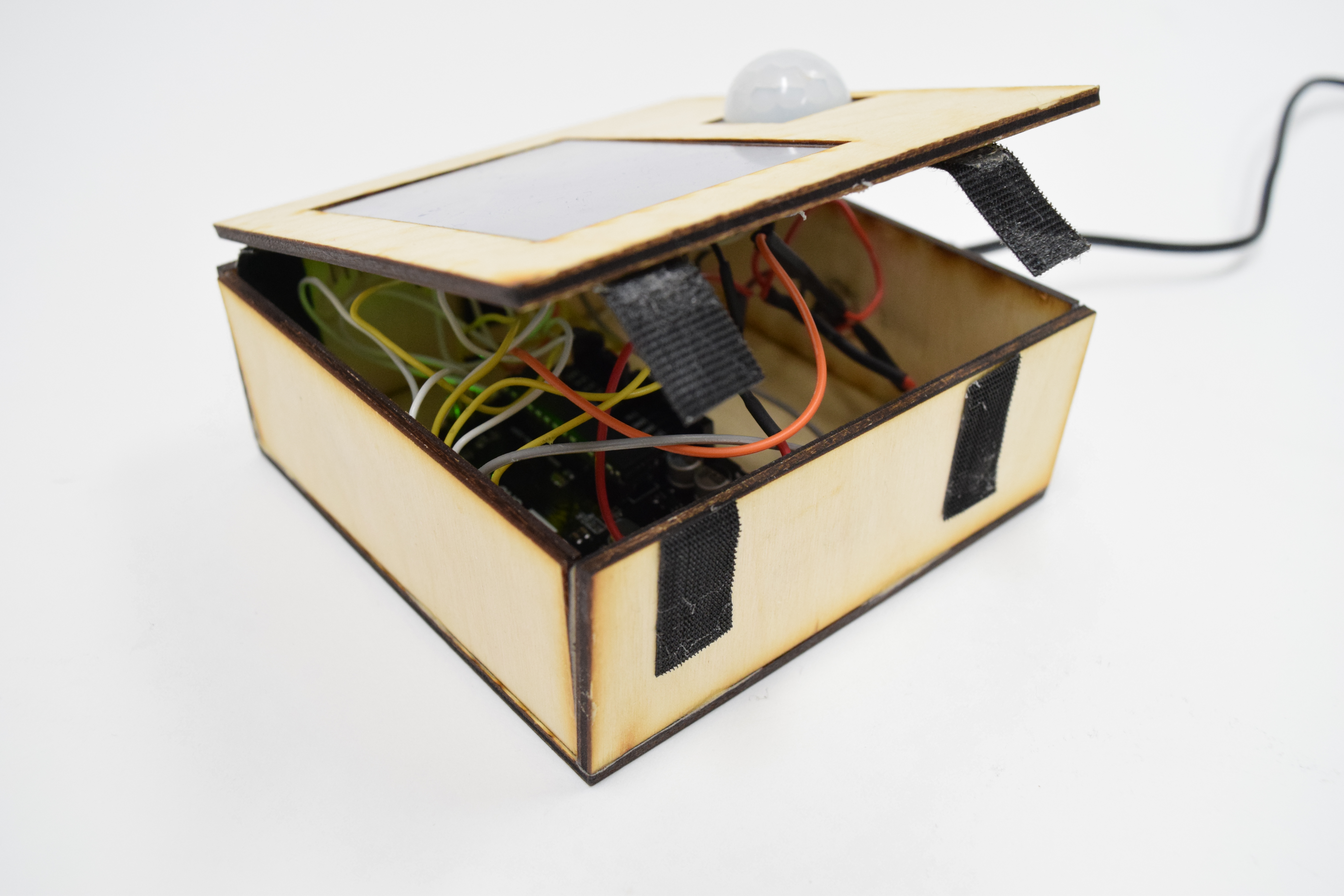
Velcro-sealed box
CONCLUSIONS
The final crit proved to be a very helpful time for us to learn about good features to add to the project. Overall response to the box itself was very positive- both from older friends and from peers. Overall, it seemed as if both groups were very willing to use the box in daily life. Some feedback was that it may have been better to change the design of the box so that it draws a little more attention to itself- like a coat of varnish and maybe a blinking LED light and some sound (these were all suggestions that came from 3 separate people). While we did what our client wanted (these were all ideas we discussed with him), they are certainly ideas we would have implemented.
Additionally, the idea of the demo in its simple form- without the Google calendar implementation- also garnered a good amount of support. It appeared to be a good solution for those who didn’t use a google calendar, though of course there was also the opposing side of the same argument- that the keyboard was too small and the Google Calendar would have worked much better. This reasoning, however, often came from the general sentiment that the screen itself was too small. We’d already bought the largest, reasonably priced screen that we could find, and going any bigger would have given us marginal improvements of size with dramatic price increases. By the end of this discussion, there was a mention that this product would have been great on an iPad, which then begged the question- why not mount an iPad by the door instead? Why this project? To us, this is because an iPad is a one-size-fits-all, expensive solution, whereas our box is a this-size-fits-Jim, more cost-effective solution.
Overall, this project is a quite simple idea, but, under the hood, the complexities of this project were so great that factors like time, WiFi access, and constraints in memory played a big role in making this project much harder to realize. While we were able to put together a final product that satisfied the needs of our client, we would have been much happier with a product that would have been able to access WiFi, a circumstance we couldn’t control. Testing and overall product development were severely impedimented by this, despite the fact that most of the code was written and only needed to be tested. Everything is currently in progress and will soon be updated to meet our standards of functionality, as well as Jim’s. Looking forward, one thing to change would be to ensure that the WiFi chip we are using has much more memory and is able to effectively access the internet from where it is being tested, and to pre-check that the devices being used are always compatible. Compatibility played a large role in the effectiveness of this project. Because IoT projects require hardware, connectivity, and software to work together seamlessly, the presence of many roadblocks in this path made a final product much more difficult to develop with the resources on hand. Still, the learning curve, though steep, was important and taught us a lot about the importance of developing products that are viable and useful. With a larger timeframe, however, we are fully confident that we can produce a fully functioning reminder box for Jim by the time spring semester rolls around.
TECHNICAL DETAILS
Code
The following code is a completely locally-hosted, on-premise code block operating only with the Arduino Uno R3, which takes entries based on the next day to add to the calendar:
/* this code is written for the Arduino component of the reminder box, and is the demo code,
 * which allows the user to manually enter information about the things he/she needs for the
 * next day. The reminder box pulls information on the day of the week (set based on an example
 * schedule here) and prompts the user (whenever the motion sensor is tripped) to check off
 * whether they have everything or if they want to add anything to the list of things they need
 * for tomorrow.
 */

//libraries
#include <Adafruit_GFX.h>
#include <SPI.h>
#include <Wire.h>
#include <Adafruit_ILI9341.h>
#include <TouchScreen.h>
#include <stdint.h>
#include <DS3231.h>

//Touchscreen pins
#define YP A2
#define XM A3
#define YM 8
#define XP 9

//Calibration data
#define TS_MINX 150
#define TS_MINY 120
#define TS_MAXX 920
#define TS_MAXY 940

#define MINPRESSURE 10
#define MAXPRESSURE 1000

#define IsWithin(x, a, b) ((x>=a)&&(x<=b))

TouchScreen ts = TouchScreen(XP, YP, XM, YM, 600);

#define TFT_CS 10
#define TFT_DC 9
Adafruit_ILI9341 tft = Adafruit_ILI9341(TFT_CS, TFT_DC);

DS3231 rtc(SDA, SCL);

String dailyStuff[7] = {"\n agenda\n coat\n umbrella",
                       "\n wallet\n documents",
                       "\n gym bag\n dog treats",
                       "\n files\n pen drive",
                       "\n cell phone\n passport",
                       "\n car keys\n bags",
                       "\n art supplies\n laptop charger"};

// define variables for if he has everything and the new and old strings
bool hasEverything = false;
String old = "";
String updated = "";
String printed = updated;
String add = "";
String tomorrowString = "";
String tb = "";
int day;

//define LED and motion sensor pins
const int MOTION_SENSOR = 3;
const int LED = 4;
// set boolean for startup
bool remind = false;

int index = 0;

int bx;
int by;

bool scrollUp;
bool scrollDown;
bool adding;

const char textLimit = 25;
char MyBuffer[textLimit];

#define FRAME_X 210
#define FRAME_Y 180
#define FRAME_W 50
#define FRAME_H 40

#define GREENBUTTON_X (FRAME_X + FRAME_W)
#define GREENBUTTON_Y FRAME_Y
#define GREENBUTTON_W FRAME_W
#define GREENBUTTON_H FRAME_H

void drawFrame() {
  tft.drawRect(GREENBUTTON_X, GREENBUTTON_Y + 7, FRAME_W, FRAME_H, ILI9341_BLACK);
}

void addMode() {
  keyboard();
  while (adding) {
    GetKeyPress(MyBuffer);
  }
  yesBtn();
}

// updates the string needed for the day based on the time
void dayUpdate() {
  if (rtc.getTime().hour == 23 && rtc.getTime().min == 58) {
    tb = tomorrowString;
    day = rtc.getTime().dow;
    updated = dailyStuff[day] + tb;
    tomorrowString = "";
  }
}

void checkScroll() {
  TSPoint p = ts.getPoint();
  bx = map(p.y, TS_MINX, TS_MAXX, 0, tft.width());
  by = map(p.x, TS_MINY, TS_MAXY, tft.height(),0);
  if ((260 < bx  && bx < 300) && (65 < by && by < 100)) {
    scrollUp = true;
  }
  else if ((260 < bx && bx < 300) && (100 < by && by < 135)) {
    scrollDown = true;
  }
  if (scrollDown) {
    index = updated.indexOf("\n ");
    if (index == -1) {
      printed = updated.substring(index + 2);
      tft.println(printed);
    }
    scrollDown = false;
  }

  if (scrollUp) {
    index = updated.indexOf(printed);
    if (index != 0) {
      printed = updated.lastIndexOf("\n ", index);
      tft.println(printed);
    }
    scrollUp = false;
  }
}

//arrays for keyboard
const char Mobile_KB[3][13] PROGMEM = {
  {0, 13, 10, 'Q', 'W', 'E', 'R', 'T', 'Y', 'U', 'I', 'O', 'P'},
  {1, 12, 9, 'A', 'S', 'D', 'F', 'G', 'H', 'J', 'K', 'L'},
  {3, 10, 7, 'Z', 'X', 'C', 'V', 'B', 'N', 'M'},
};

const char Mobile_NumKeys[3][13] PROGMEM = {
  {0, 13, 10, '1', '2', '3', '4', '5', '6', '7', '8', '9', '0'},
  {0, 13, 10, '-', '/', ':', ';', '(', ')', '$', '&', '@', '"'},
  {5, 8, 5, '.', '\,', '?', '!', '\''}
};

const char Mobile_SymKeys[3][13] PROGMEM = {
  {0, 13, 10, '[', ']', '{', '}', '#', '%', '^', '*', '+', '='},
  {4, 9, 6, '_', '\\', '|', '~', '<', '>'}, //4
  {5, 8, 5, '.', '\,', '?', '!', '\''}
};

//function that actually makes the keyboard look like a keyboard (has buttons and prints letters)
void MakeKB_Button(const char type[][13])
{
  tft.setTextSize(2);
  tft.setTextColor(ILI9341_WHITE);
  for (int y = 0; y < 3; y++)
  {
    int ShiftRight = 15 * pgm_read_byte(&(type[y][0]));
    for (int x = 3; x < 13; x++)
    {
      if (x >= pgm_read_byte(&(type[y][1]))) break;

      drawButton(15 + (30 * (x - 3)) + ShiftRight, 100 + (30 * y), 20, 25); // this will draw the button on the screen by so many pixels
      tft.setCursor(20 + (30 * (x - 3)) + ShiftRight, 105 + (30 * y));
      tft.print(char(pgm_read_byte(&(type[y][x]))));
    }
  }
  //ShiftKey
  drawButton(15, 160, 35, 25);
  tft.setCursor(27, 168);
  tft.print('^');

  //Special Characters
  drawButton(15, 190, 35, 25);
  tft.setCursor(21, 195);
  tft.print(F("SP"));

  //BackSpace
  drawButton(270, 160, 35, 25);
  tft.setCursor(276, 165);
  tft.print(F("BS"));

  //Return
  drawButton(270, 190, 35, 25);
  tft.setCursor(276, 195);
  tft.print(F("RT"));

  //Spacebar
  drawButton(60, 190, 200, 25);
  tft.setCursor(105, 195);
  tft.print(F("SPACE BAR"));
}

//function that draws buttons
void drawButton(int x, int y, int w, int h)
{
  // grey
  tft.fillRoundRect(x - 3, y + 3, w, h, 3, ILI9341_LIGHTGREY); //Button Shading

  // white
  tft.fillRoundRect(x, y, w, h, 3, ILI9341_WHITE);// outter button color

  //red
  tft.fillRoundRect(x + 1, y + 1, w - 1 * 2, h - 1 * 2, 3, ILI9341_RED); //inner button color
}

void GetKeyPress(char * textBuffer)
{
  static bool shift = false, special = false, back = false, lastSp = false, lastSh = false;
  static int bufIndex = 0;
  TSPoint p = ts.getPoint();
  Serial.print("bx = "); Serial.print(bx); Serial.print(" by = "); Serial.println(by);
  Serial.println(p.z);
  Serial.println("we're here");
  if (p.z >= 0)
  {
    //ShiftKey
    if (TouchButton(-10, 160, 30, 25))
    {
      shift = !shift;
      delay(200);
    }

    //Special Characters
    if (TouchButton(-10, 190, 30, 25))
    {
      special = !special;
      delay(200);
    }

    if (special != lastSp || shift != lastSh) //Start of changing the keys and make it look different
    {
      if (special)
      {
        if (shift)
        {
          tft.fillScreen(ILI9341_BLUE);
          MakeKB_Button(Mobile_SymKeys);
        }
        else
        {
          tft.fillScreen(ILI9341_BLUE);
          MakeKB_Button(Mobile_NumKeys);
        }
      }
      else
      {
        tft.fillScreen(ILI9341_BLUE);
        MakeKB_Button(Mobile_KB);
        tft.setTextColor(0xffff, 0xf800);
      }

      if (special)
        tft.setTextColor(0x0FF0, 0xf800);
      else
        tft.setTextColor(0xFFFF, 0xf800);

      tft.setCursor(21, 195);
      tft.print(F("SP"));

      if (shift)
        tft.setTextColor(0x0FF0, 0xf800);
      else
        tft.setTextColor(0xffff, 0xf800);

      tft.setCursor(27, 168);
      tft.print('^');

      lastSh = shift;
      lastSp = special;
      lastSh = shift;
    }//End of changing the keys and make it look different

    for (int y = 0; y < 3; y++)
    {
      int ShiftRight;
      if (special)
      {
        if (shift) //special+shift = symbol
          ShiftRight = 15 * pgm_read_byte(&(Mobile_SymKeys[y][0]));
        else //special only = number
          ShiftRight = 15 * pgm_read_byte(&(Mobile_NumKeys[y][0]));
      }
      else //alphabet
        ShiftRight = 15 * pgm_read_byte(&(Mobile_KB[y][0]));

      for (int x = 3; x < 13; x++)
      {
        if (x >=  (special ? (shift ? pgm_read_byte(&(Mobile_SymKeys[y][1])) : pgm_read_byte(&(Mobile_NumKeys[y][1]))) : pgm_read_byte(&(Mobile_KB[y][1])) )) break;

        if (TouchButton((33 * (x - 3)) + ShiftRight - 14, 100 + (30 * y), 20, 25)) // this will draw the button on the screen by so many pixels
        {
          if (bufIndex < (textLimit - 1))
          {
            delay(200);

            if (special)
            {
              if (shift)
                textBuffer[bufIndex] = pgm_read_byte(&(Mobile_SymKeys[y][x]));
              else
                textBuffer[bufIndex] = pgm_read_byte(&(Mobile_NumKeys[y][x]));
            }
            else
              textBuffer[bufIndex] = (pgm_read_byte(&(Mobile_KB[y][x])) + (shift ? 0 : ('a' - 'A')));

            bufIndex++;
          }
          break;
        }
      }
    }

    //Spacebar
    if (TouchButton(35, 190, 200, 25))
    {
      textBuffer[bufIndex++] = ' ';
      delay(200);
    }

    //BackSpace
    if (TouchButton(268, 160, 30, 25))
    {
      if ((bufIndex) > 0)
        bufIndex--;
      textBuffer[bufIndex] = 0;
      tft.setTextColor(0, ILI9341_BLUE);
      tft.setCursor(15, 80);
      tft.print(F("                          "));
      delay(200);
    }

    //Return
    if (TouchButton(268, 190, 30, 25))
    {
      tomorrowString = tomorrowString + textBuffer + "\n ";
      Serial.println(textBuffer);
      Serial.println("we got here too");
      adding = false;
      while (bufIndex > 0)
      {
        bufIndex--;
        textBuffer[bufIndex] = 0;
      }

      tft.setTextColor(0, ILI9341_BLUE);
      tft.setCursor(15, 80);
      tft.print(F("                         "));
      Serial.println(tomorrowString);
      yesBtn();
    }
  }
  tft.setTextColor(0xffff, 0xf800);
  tft.setCursor(15, 80);
  tft.print(textBuffer);
}

//Makes you know if the point that you touched is in the range computed by x,y,w,h
byte TouchButton(int x, int y, int w, int h)
{
  int X, Y;
  // Retrieve a point
  TSPoint p = ts.getPoint();
  Y = map(p.x, TS_MINY, TS_MAXY, tft.height(), 0);
  X = map(p.y, TS_MINX, TS_MAXX, 0, tft.width());

  return (IsWithin(X, x, x + w) & IsWithin(Y, y, y + h));
}

void keyboard() {
  tft.fillScreen(ILI9341_BLUE);
  MakeKB_Button(Mobile_KB);
  GetKeyPress(MyBuffer);
}

void yesBtn()
{
  tft.fillScreen(ILI9341_BLUE);
  //Asking Jim text
  tft.setCursor(10, 10);
  tft.setTextColor(ILI9341_WHITE);
  tft.setTextSize(2);
  tft.println("Hey Jim! Do you have      what you need for today?");
  //Printing item list
  tft.setTextSize(2);
  tft.println(updated);
  //Scroll buttons
  tft.fillRect(GREENBUTTON_X + 6, 60, GREENBUTTON_W - 12, 70, ILI9341_LIGHTGREY);
  tft.drawRect(GREENBUTTON_X + 6, 60, GREENBUTTON_W - 12, 35, ILI9341_BLACK);
  tft.drawRect(GREENBUTTON_X + 6, 95, GREENBUTTON_W - 12, 35, ILI9341_BLACK);
  //Scroll up arrow
  tft.setCursor(GREENBUTTON_X + 17, 65);
  tft.setTextColor(ILI9341_BLACK);
  tft.setTextSize(3);
  tft.println((char)24);
  //Scroll down arrow
  tft.setCursor(GREENBUTTON_X + 17, 100);
  tft.setTextColor(ILI9341_BLACK);
  tft.setTextSize(3);
  tft.println((char)25);
  //Add item button
  tft.fillRect(GREENBUTTON_X, 138, GREENBUTTON_W, GREENBUTTON_H, ILI9341_DARKGREEN);
  tft.drawRect(GREENBUTTON_X, 138, GREENBUTTON_W, GREENBUTTON_H, ILI9341_BLACK);
  tft.setCursor(GREENBUTTON_X + 7, 150);
  tft.setTextColor(ILI9341_WHITE);
  tft.setTextSize(2);
  tft.println("ADD");
  //YES button
  tft.fillRect(GREENBUTTON_X, GREENBUTTON_Y + 7, GREENBUTTON_W, GREENBUTTON_H, ILI9341_RED);
  drawFrame();
  tft.setCursor(GREENBUTTON_X + 7 , GREENBUTTON_Y + (GREENBUTTON_H / 2));
  tft.setTextColor(ILI9341_WHITE);
  tft.setTextSize(2);
  tft.println("YES");
}

void byeBtn()
{
  //Have a good day text
  tft.fillScreen(ILI9341_BLUE);
  tft.setCursor(10, 10);
  tft.setTextColor(ILI9341_WHITE);
  tft.setTextSize(4);
  tft.println("Great! Have  a good day");
  //bye button
  tft.fillRect(GREENBUTTON_X, GREENBUTTON_Y + 7, GREENBUTTON_W, GREENBUTTON_H, ILI9341_GREEN);
  drawFrame();
  tft.setCursor(GREENBUTTON_X + 7 , GREENBUTTON_Y + (GREENBUTTON_H / 2));
  tft.setTextColor(ILI9341_WHITE);
  tft.setTextSize(2);
  tft.println("BYE");
}

void setup() {
  // Set up serial monitor
  Serial.begin(9600);
  pinMode(MOTION_SENSOR, INPUT);
  pinMode(LED, OUTPUT);
  tft.begin();
  rtc.begin();
  // Set up the screen at first
  tft.setRotation(1);
  yesBtn();
}

void loop() {

  dayUpdate();

  if (digitalRead(MOTION_SENSOR) == HIGH) {
    digitalWrite(LED, HIGH);
    //Serial.println("motion sensor triggered");
    remind = true;
  }
  else if (digitalRead(MOTION_SENSOR) == LOW) {
    digitalWrite(LED, LOW);
    remind = false;
  }

  if (remind == false) {
    // fills the screen with black to save power
    // and also not draw attention when not needed
    tft.fillScreen(ILI9341_BLACK);
    while (remind == false) {
      if (digitalRead(MOTION_SENSOR) == HIGH) {
        digitalWrite(LED, HIGH);
        //Serial.println("motion sensor triggered");
        remind = true;
      }
      else if (digitalRead(MOTION_SENSOR) == LOW) {
        digitalWrite(LED, LOW);
        remind = false;
      }
    }
  }

  //only do things if the motion sensor gets tripped
  if (remind == true) {
    // first read the screen to see if he did anything
  // Retrieve a point
  TSPoint p = ts.getPoint();

  //See if there's any touch data
  if (p.z > MINPRESSURE && p.z < MAXPRESSURE) {
    //Scale using the calibration #'s and rotate coordinate system
    bx = map(p.y, TS_MINX, TS_MAXX, 0, tft.width());
    by = map(p.x, TS_MINY, TS_MAXY, tft.height(),0);
    if (hasEverything == false) {
      // if he presses the button
      if ((255 < bx && bx < 310) && (192 < by && by < 230)) {
        // set hasEverything to true and execute that part of the code
        hasEverything = true;
      }
      if (hasEverything == true) {
      byeBtn();
      delay(5000);
      hasEverything = false;
      yesBtn();
  }
    }
  }

   p = ts.getPoint();

  //See if there's any touch data
  if (p.z > MINPRESSURE && p.z < MAXPRESSURE) {
    //Scale using the calibration #'s and rotate coordinate system
    bx = map(p.y, TS_MINX, TS_MAXX, 0, tft.width());
    by = map(p.x, TS_MINY, TS_MAXY, tft.height(),0);
    Serial.print("bx = "); Serial.print(bx); Serial.print(" by = "); Serial.println(by);

    // pressed add button
    if (255 < bx && bx < 310 && 143 < by && by < 181) {
      bx = 10;
      by = 10;
      adding = true;
      addMode();
    }
    checkScroll();
  }

  // if he adds stuff from serial monitor
  if (Serial.available() > 0) {
    //// upload it onto the main display
    add = Serial.readStringUntil('\n');
    updated = updated + '\n' + ' ' + add;
    Serial.println(updated);
    yesBtn();
  }

  }


}
NOTE: After it is tested and confirmed to work with the Arduino, we will be adding in the IoT version of this code, which connects with Google API to return events without the need for input.
Schematic and Design Files
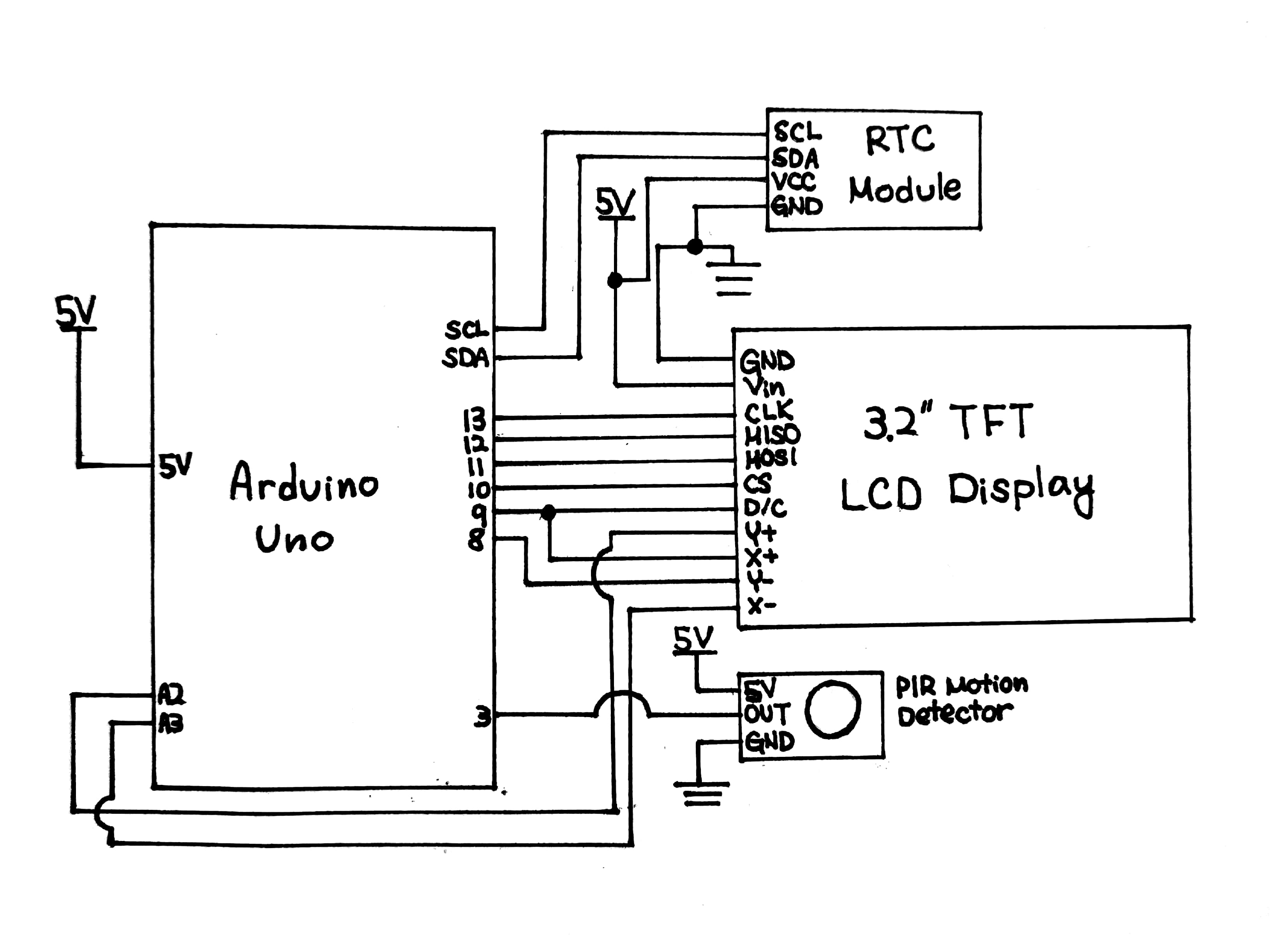
Schematic of the box at final demo
]]>
For the prototype, we started working on the memory aid that Jim identified would be a great asset in his life. Essentially, it would serve as a reminder as he’s rushing out the door to make sure that he has everything that he needs for his various meetings/that day. If you would like to read about how the initial meeting went where we identified this need, feel free to check out our documentation below.
Product
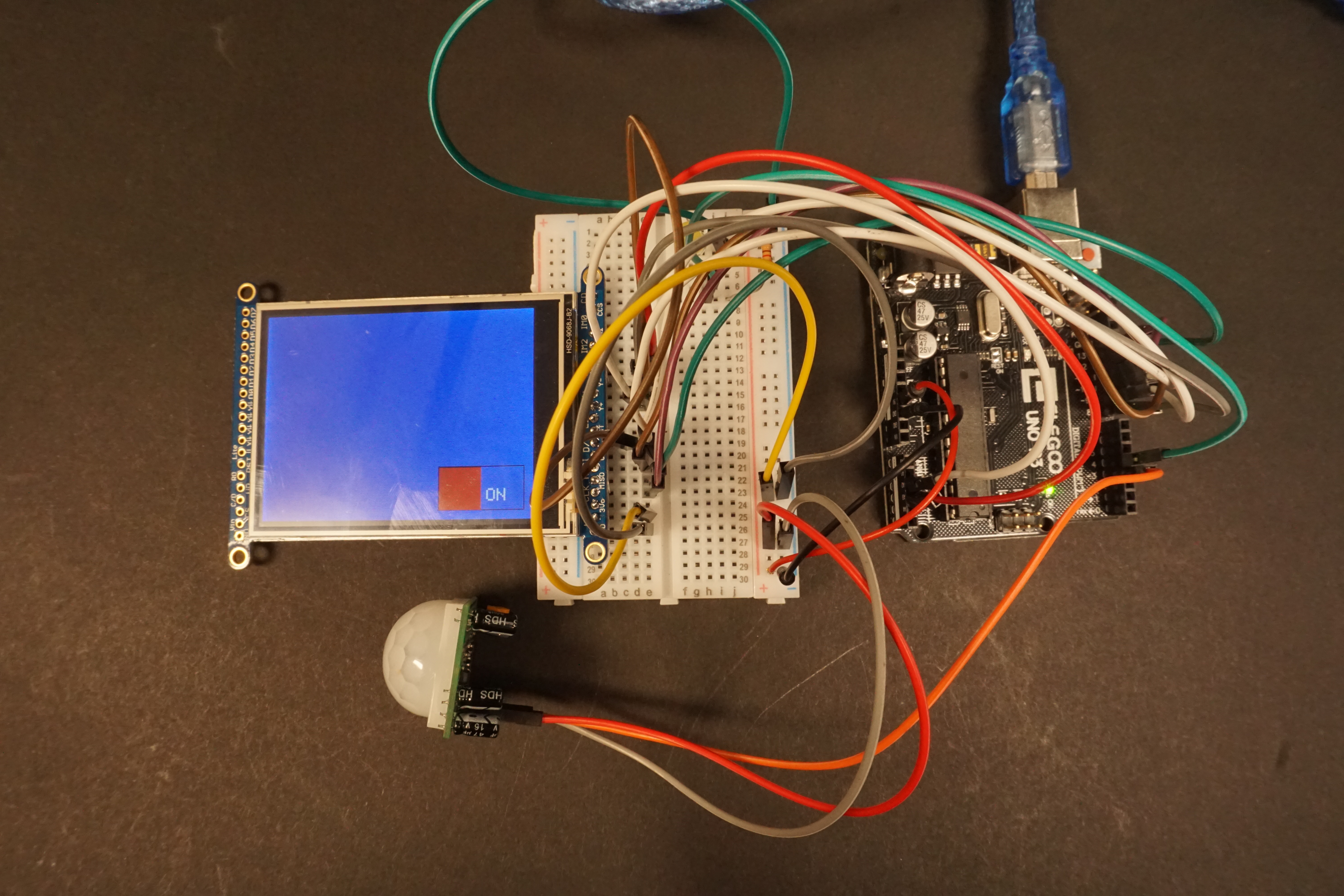
Overall view of prototype
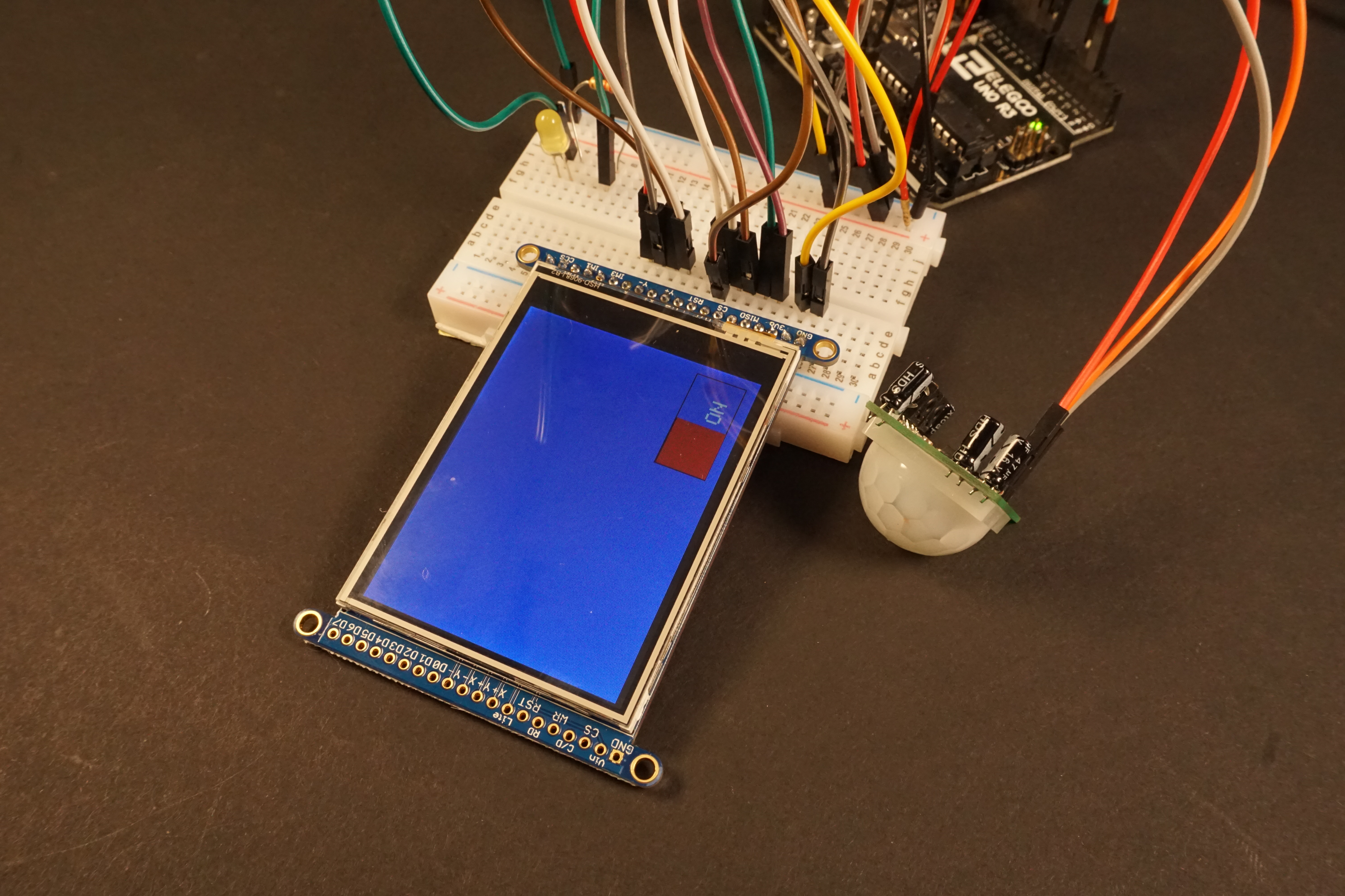
TFT Display and Motion Sensor
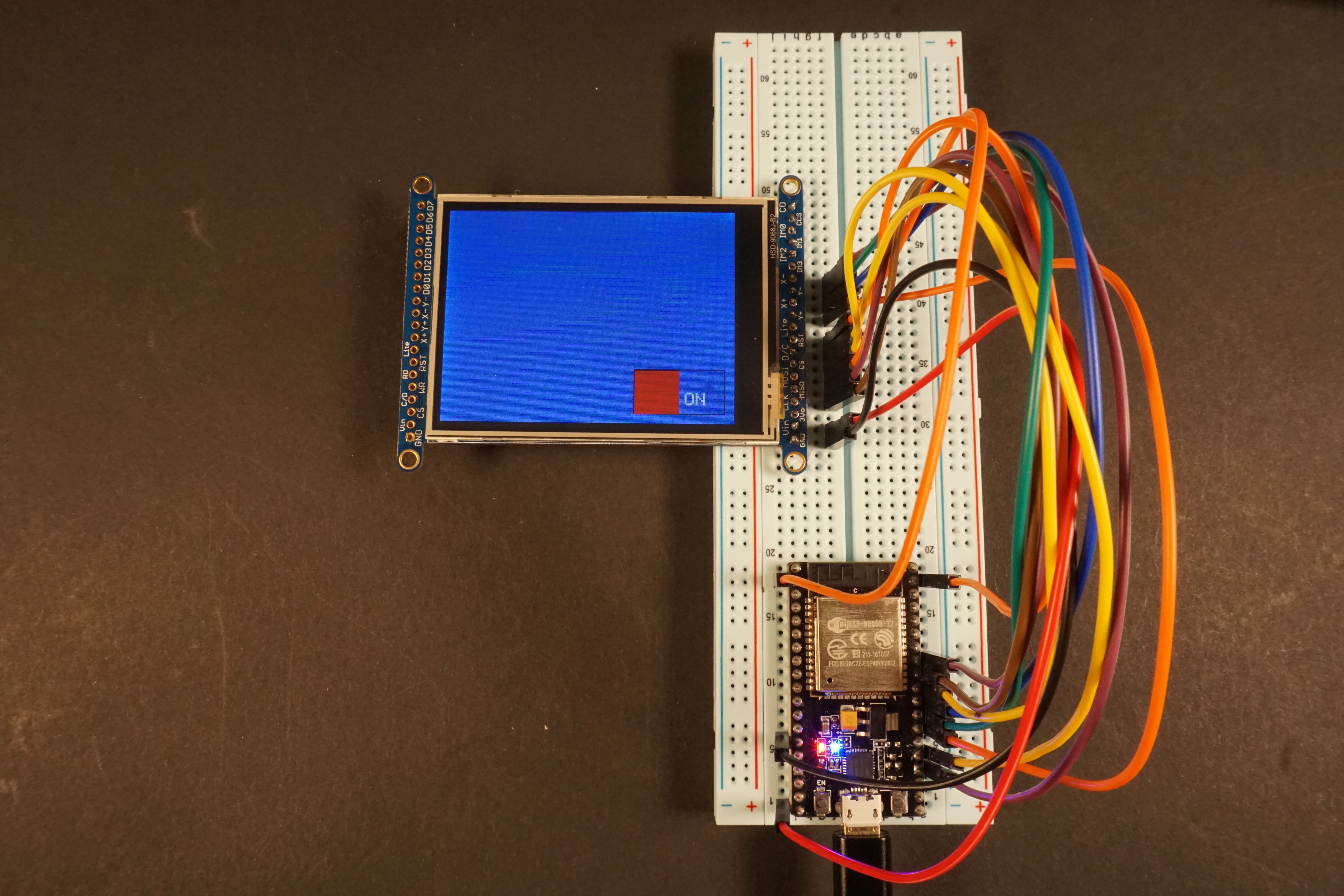
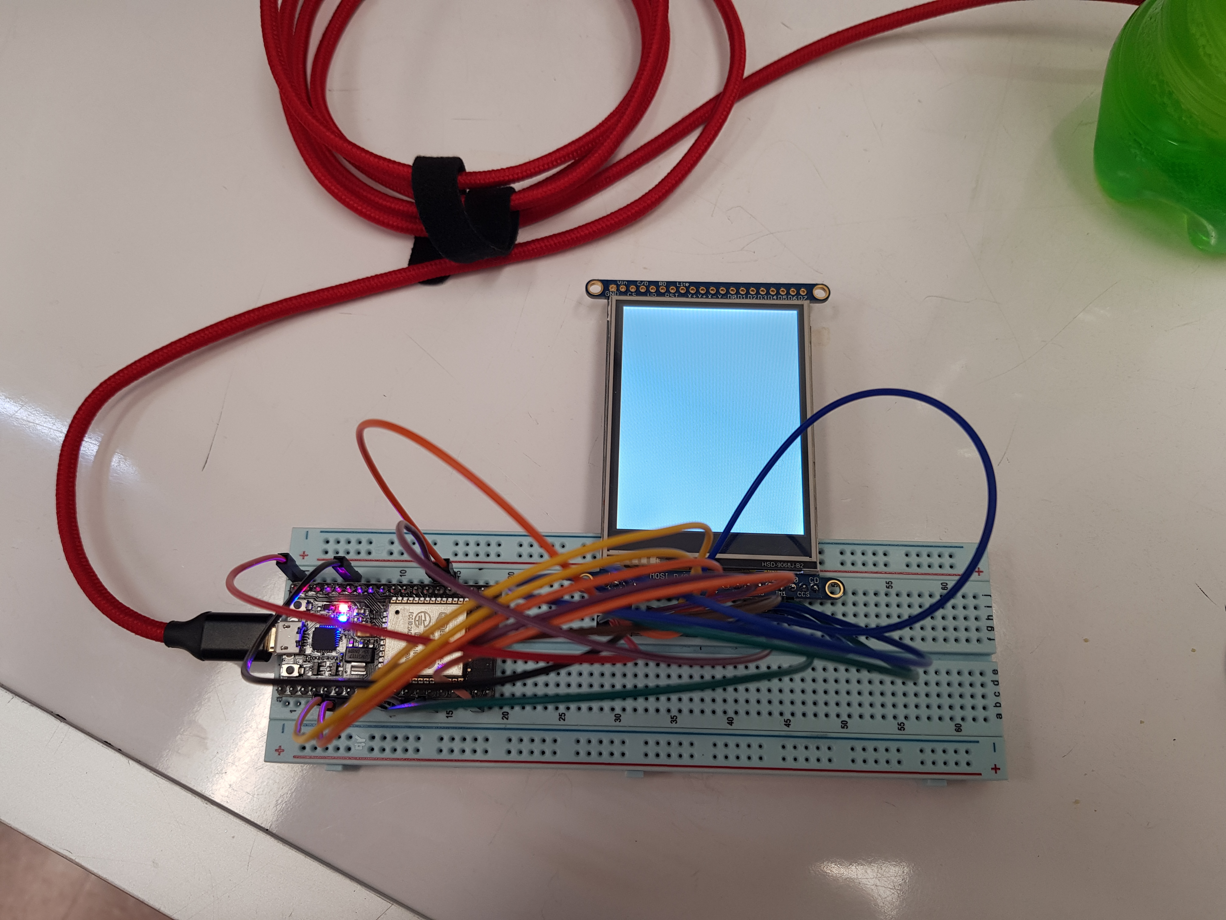
TFT Display connected to ESP32 (goal)
Our prototype demonstrates similar behavior to the final result we are trying to achieve as far as the hardware component. The motion sensor detects movement so that the system can save energy. The touchscreen display features a button that allows the user to toggle between buttons under a list of everyday items for Jim. Changing the red button green means that the user (Jim) has answered yes to having all the items he needs and is ready to leave his house. The current prototype works with inputs (the items) dictated by the user but ultimately we would like to have the display connected to the ESP32 (image above) and for the ESP32 to communicate with Jim’s Google Calendar so that it can easily know what he’ll need for every day. Unfortunately we didn’t receive the ESPs until Monday so we had to temporarily set everything up with an Arduino for this demo. The final product is intended to be stored inside a box next to Jim’s front door that can be portable.
Process
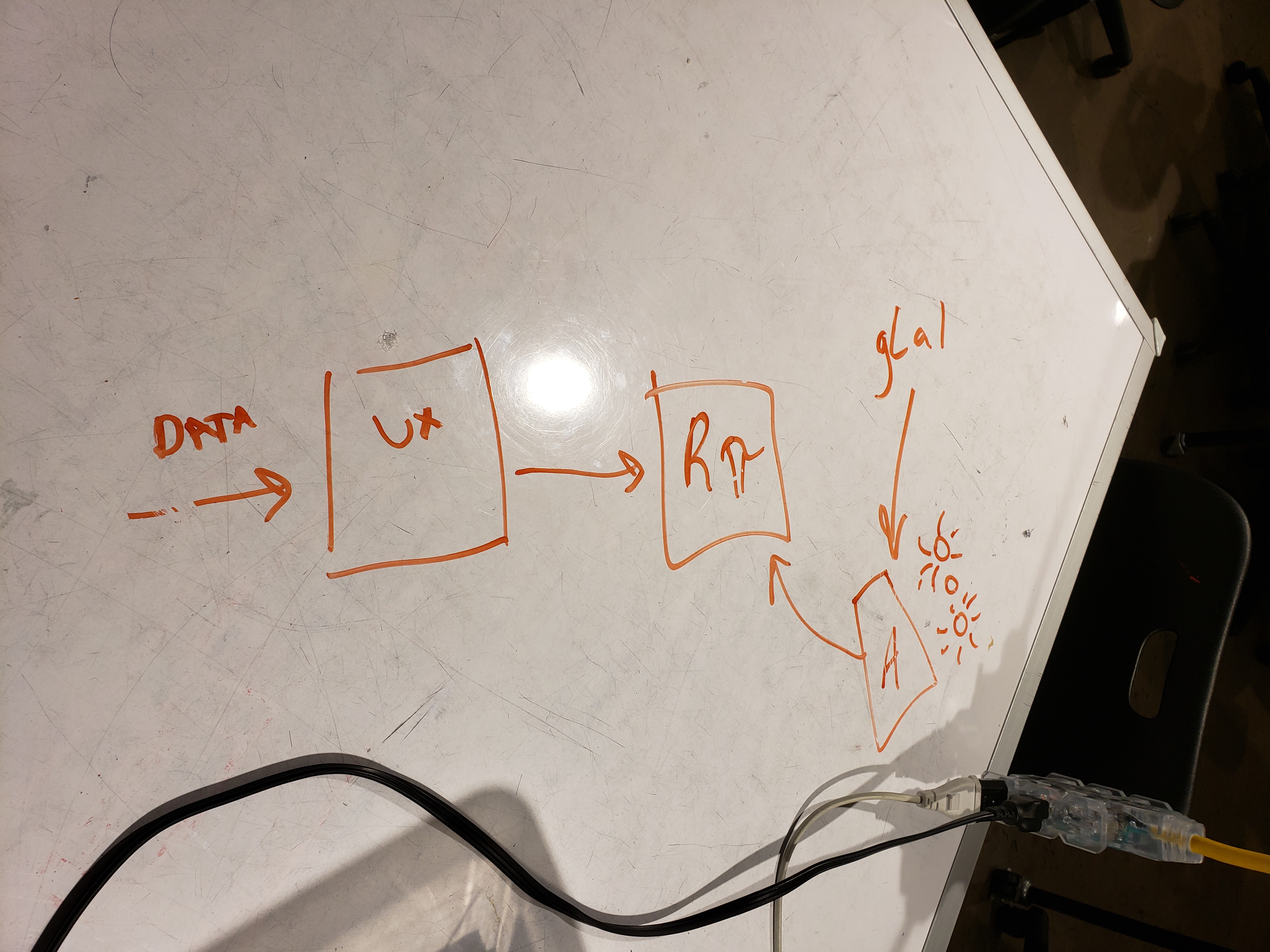
Whiteboard diagram back when the idea was to host a server using a raspberry pi instead of Google Calendar
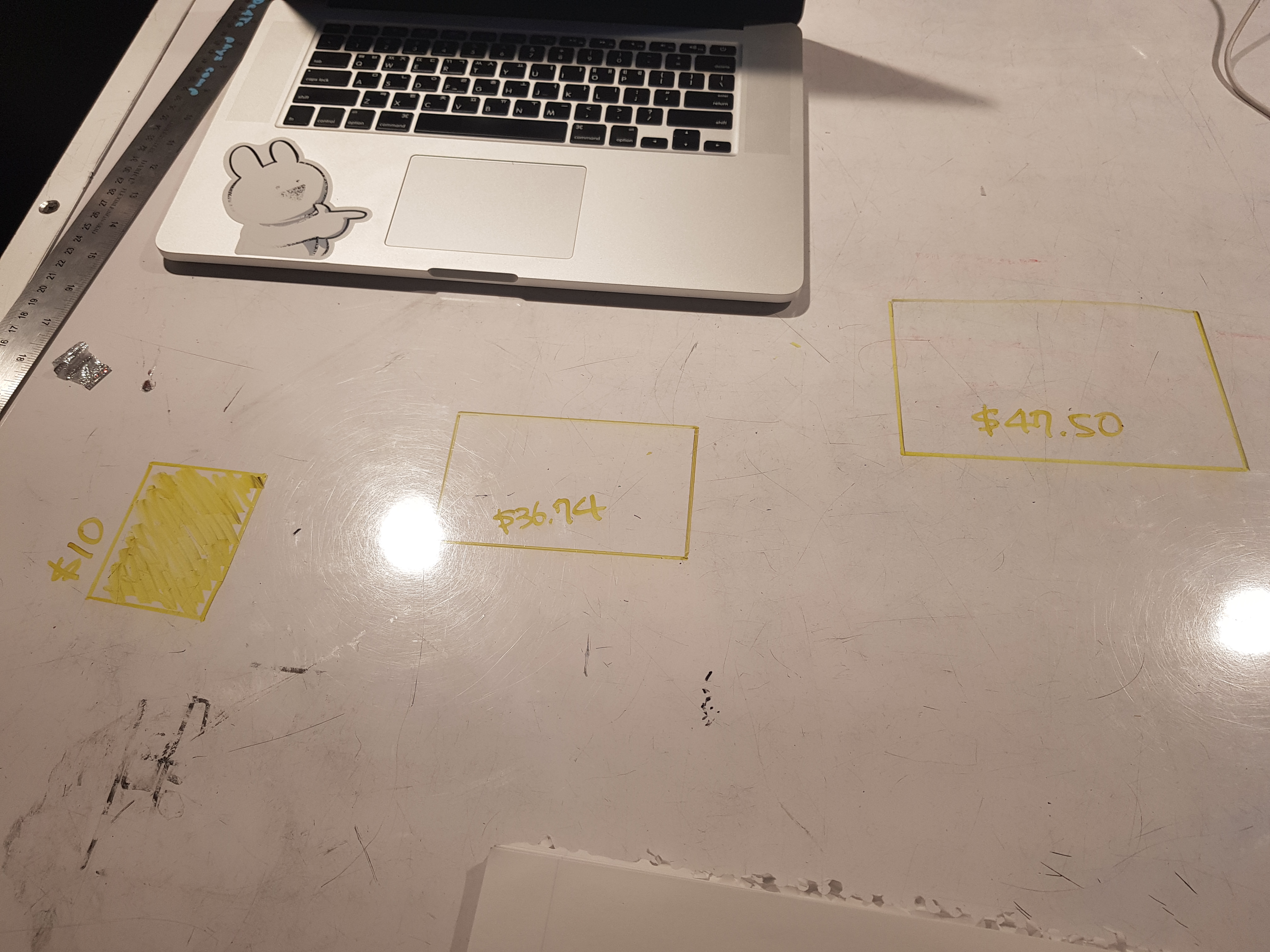
Drawing out the display sizes we could find online with a marker and ruler to debate each option, taking into account price and later shipping times
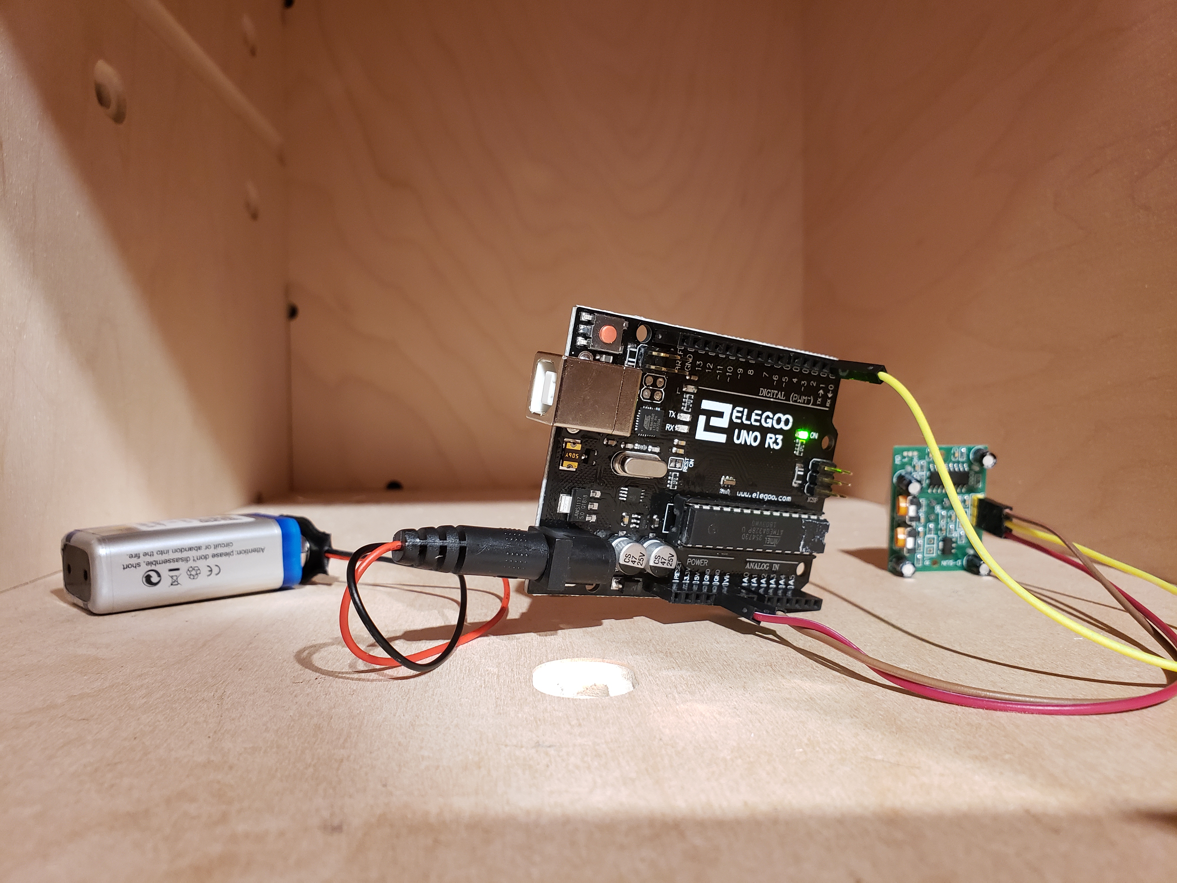
Testing if the motion detector was working as well as the range by giving it a time out in the cubbies
Sketches of icons for the common items that Jim often needs
First attempt to connect tft display to esp32
Jumpers soldered for SPI use
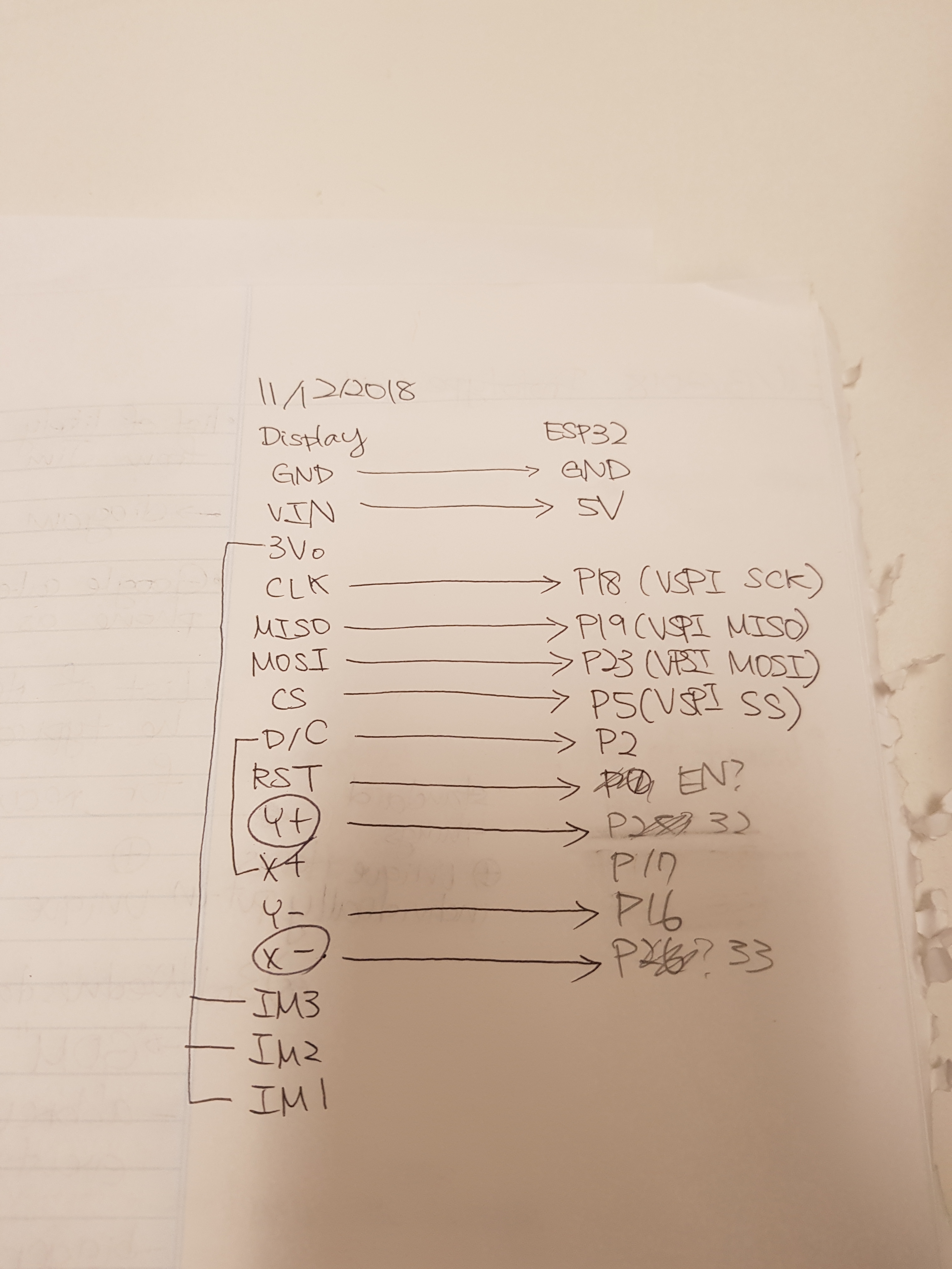
Record of pins between display and esp32
Reminder screen that displays once motion detector is triggered with daily items listed out (day of the demo)
Process
One of the major challenges for us was connecting all the ESP pins to the TFT Display pins. One of our team members is currently working on tackling this issue but we didn’t have time to do it before the demo. The bulk of the problem is the ESP32 having way more pins than the Arduino and figuring out how those pins act based off the schematic included. The majority of the other pieces (calibrating the motion sensor, connecting the motion sensor to the arduino, researching APIs to incorporate Google Calendar) was fairly easy to troubleshoot except for the API data which requires more research to implement.
We received some great advice/ideas/suggestions from this crit. During the in class portion, we received a suggestion that we should assign items to recurring events so Jim doesn’t have to manually log the items in every time. As soon as we got time to talk to Jim one on three, we asked him to send us a list of common items that he needs whenever it’s convenient for him so we can specifically look in Google Calendar for the event name and assign the items as a result. He would still have to enter the items manually for new events, however. Zach came around and gave a critique that Jim may want to use his descriptions and it would be better if the code could parse for a keyword such as list: to start the list. He also told us that he often abbreviates common events – such as GOM for Gathering of Men which will be useful for us to keep an eye out for when the Google Calender API is up and running.
We received some general aesthetic feedback as well that bigger text and a bigger screen if possible would be nice. He also told us that he would prefer to confirm he has all his objects at the end, rather than individually checking items as he goes. We also suggested there could be some sound from the box or a phone notification in case he bypasses the box without clicking cancel (something we have to implement for the final product). Jim gave us the helpful feedback that though his phone is often on him, he doesn’t always have it on so a phone notification might not be the best method. We also got into a handy conversation with Zach about using a 9V battery vs plugging the device into the wall. As a result, we now know to keep an eye out for the distance between the front door and the nearest outlet.
Our next steps for this project is to get the Google Calendar API up and running so that we can make sure everything is working right/design the user experience from the web portion of the project. We also have to resolve how to get the TFT Display Screens to properly communicate with the ESP32. Lastly, we must figure out how to display an icon image on the display screen or draw the item out by coordinates for better legibility and to make it more interesting.
]]>
The LEDs poking out indicate if the chargers are inside my backpack in an organized fashion.
This backpack lets me know if I have the chargers I need in my backpack by lighting up the LEDs on the top and forces me to organize them at the same time.
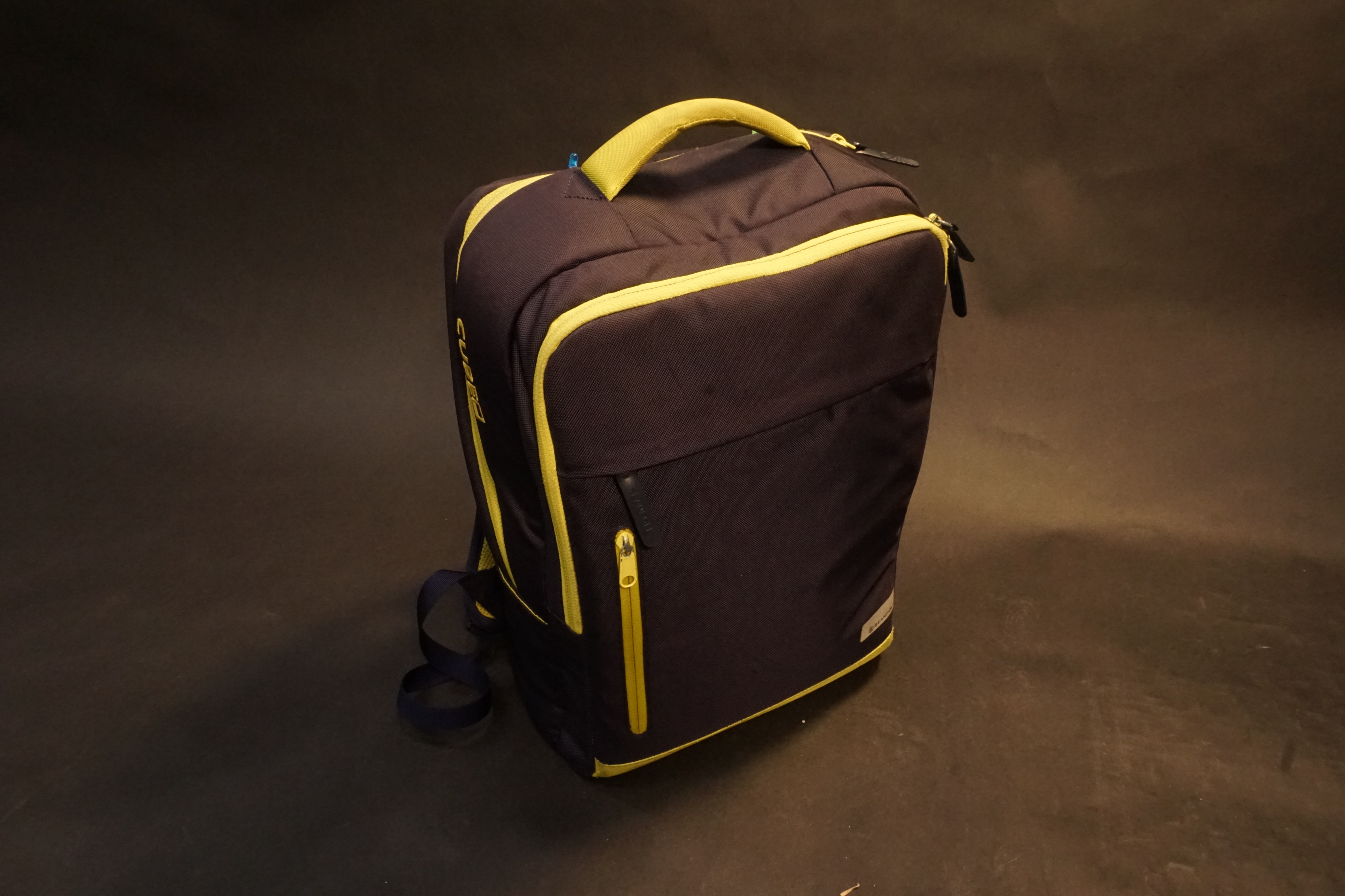
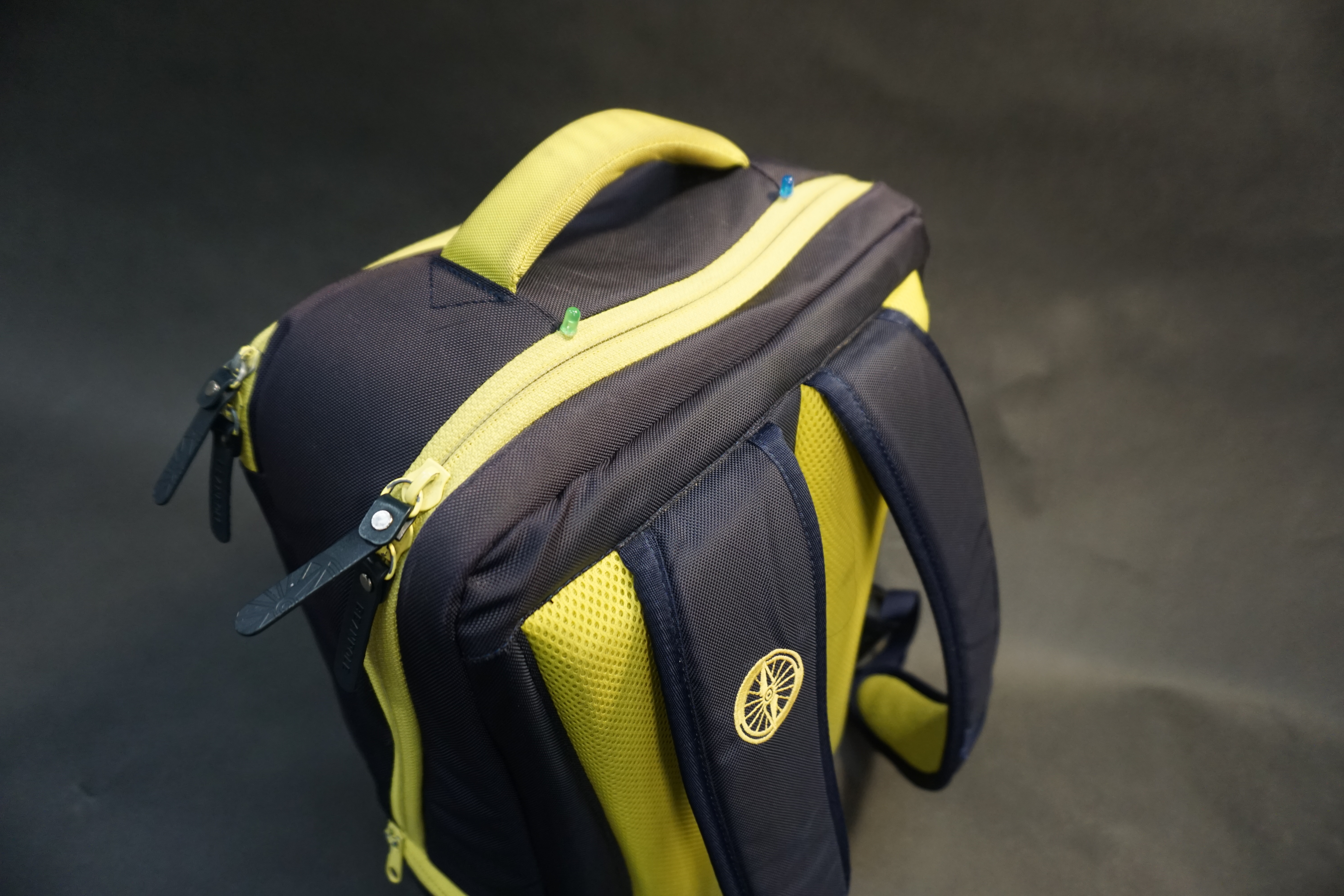
Front view of the Semi Hi-Tech Backpack
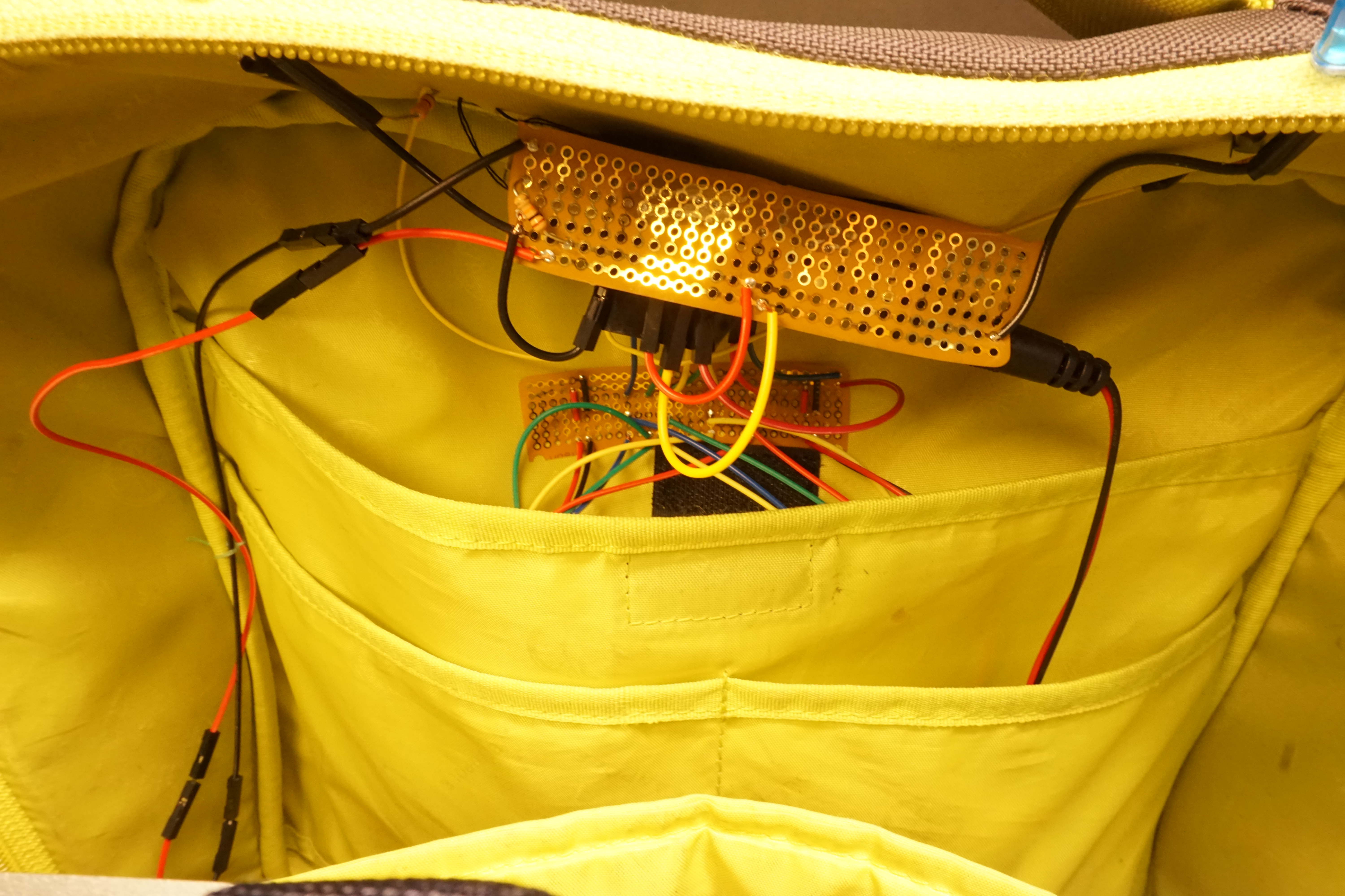
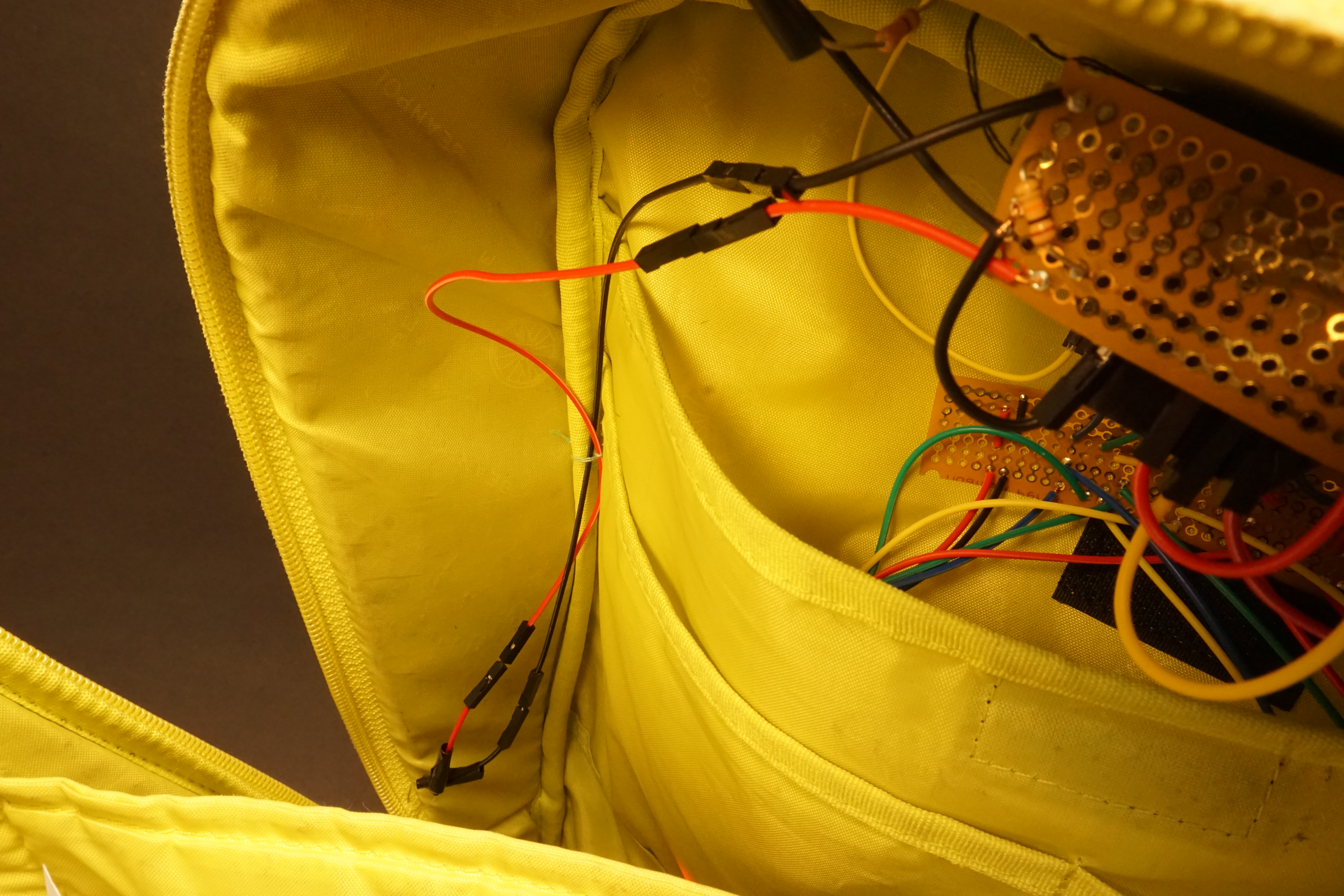
Overview of the electronics inside the backpack
Wire for the pressure sensor on the bottom of the backpack runs down the side.
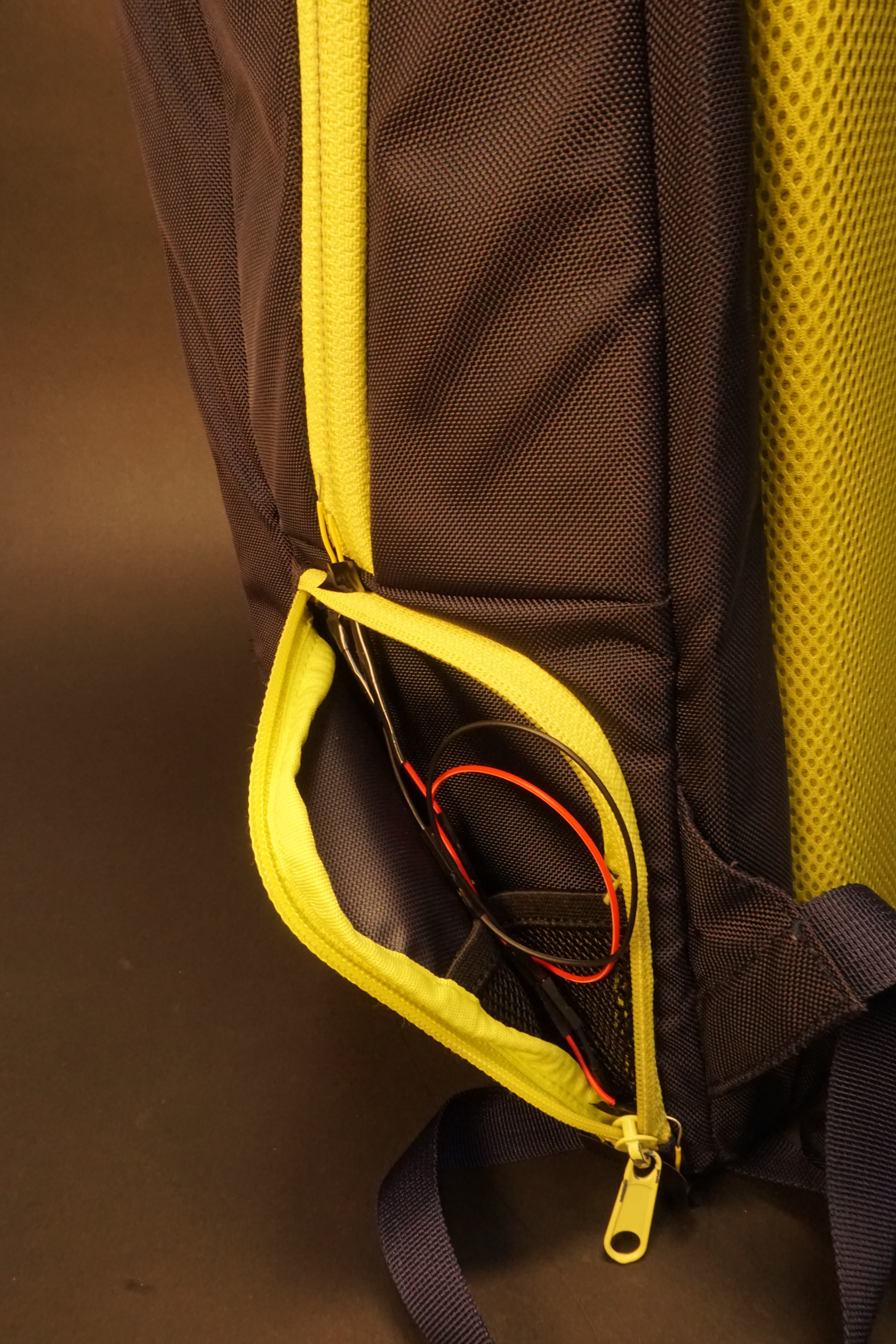
Wire connecting the pressure sensor is hidden using the side pocket.
Code for the project:
/*
Project Title: Semi Hi-Tech Backpack
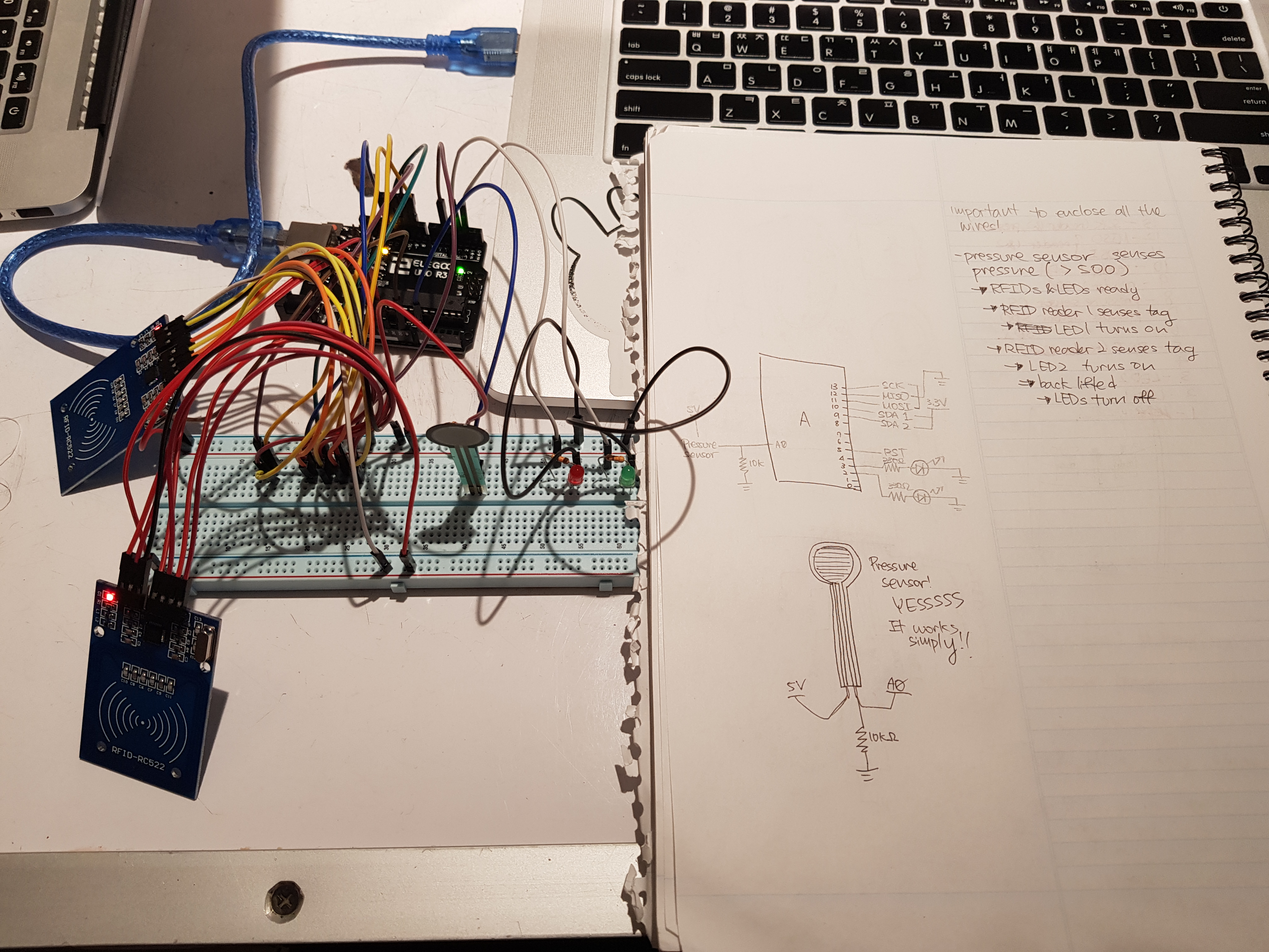
Description: The project uses two RFID sensors to read RFID tags and compare it to the IDs of known tags. When the correct RFID tag is read by the reader, respective LEDs would turn on to indicate that the RFID tag has been sensed. This entire code will only run when the force sensitive resistor reads pressure, which is equal to when the backpack is put on the floor.
RST Pin 5
MOSI Pin 11
MISO Pin 12
SCK Pin 13
*/
//include libraries
#include <SPI.h>
#include <MFRC522.h>
//define important rfid reader pins
#define RST_PIN 5
#define SS_1_PIN 9 //same to reader 0
#define SS_2_PIN 10 //same to reader 1
//some necessary RFID stuff
#define NUM_OF_READERS 2
MFRC522 mfrc522[NUM_OF_READERS]; //Create MFRC522 instance
//set "simpler" pins
const int PRESSUREPIN = A0;
const int LED1PIN = 2;
const int LED2PIN = 3;
//"simpler" variables
int force;
void setup() {
//Initiate SPI bus
SPI.begin();
//Initiate each MFRC522 card
mfrc522[0].PCD_Init(SS_1_PIN, RST_PIN);
mfrc522[1].PCD_Init(SS_2_PIN, RST_PIN);
//set up "simpler" pins
pinMode (PRESSUREPIN, INPUT);
pinMode (LED1PIN, OUTPUT);
digitalWrite (LED1PIN, LOW);
pinMode (LED2PIN, OUTPUT);
digitalWrite (LED2PIN, LOW);
}
void loop() {
//read pressure
force = analogRead(PRESSUREPIN);
//IDs I'm looking for
byte card1[4] = {69, 96, 94, 201};
byte card2[4] = {181, 70, 94, 201};
//backpack is resting on the floor  if (force > 100) {
//create variables for rfids that the reader finds
byte readCard1[4];
byte readCard2[4];
//Sensing the stickers
if (mfrc522[0].PICC_IsNewCardPresent() && mfrc522[0].PICC_ReadCardSerial()) {
byte readCard1[4];
for (uint8_t i = 0; i < 4; i++) { //put the id number that the reader found into the variable
readCard1[i] = mfrc522[0].uid.uidByte[i];
}
//compare the wanted id and found id
if (compareArrays(readCard1, card1)) {
digitalWrite(LED1PIN, HIGH);
}
}
if (mfrc522[1].PICC_IsNewCardPresent() && mfrc522[1].PICC_ReadCardSerial()) {
byte readCard2[4];
for (uint8_t i = 0; i < 4; i++) {
readCard2[i] = mfrc522[1].uid.uidByte[i];
}
if (compareArrays(readCard2, card2)) {
digitalWrite(LED2PIN, HIGH);
}
}
//Halt PICC
mfrc522[0].PICC_HaltA();
mfrc522[1].PICC_HaltA();
//Stop encryption on PCD
mfrc522[0].PCD_StopCrypto1();
mfrc522[1].PCD_StopCrypto1();
}
//if backpack is off the floor, reset every value
else {
digitalWrite(LED1PIN, LOW);
digitalWrite(LED2PIN, LOW);
}
}
bool compareArrays(byte array1[], byte array2[]) {
for (int i = 0; i < 4; i++) {
if (array1[i] != array2[i]) return false;
}
return true;
}
if (force > 100) {
//create variables for rfids that the reader finds
byte readCard1[4];
byte readCard2[4];
//Sensing the stickers
if (mfrc522[0].PICC_IsNewCardPresent() && mfrc522[0].PICC_ReadCardSerial()) {
byte readCard1[4];
for (uint8_t i = 0; i < 4; i++) { //put the id number that the reader found into the variable
readCard1[i] = mfrc522[0].uid.uidByte[i];
}
//compare the wanted id and found id
if (compareArrays(readCard1, card1)) {
digitalWrite(LED1PIN, HIGH);
}
}
if (mfrc522[1].PICC_IsNewCardPresent() && mfrc522[1].PICC_ReadCardSerial()) {
byte readCard2[4];
for (uint8_t i = 0; i < 4; i++) {
readCard2[i] = mfrc522[1].uid.uidByte[i];
}
if (compareArrays(readCard2, card2)) {
digitalWrite(LED2PIN, HIGH);
}
}
//Halt PICC
mfrc522[0].PICC_HaltA();
mfrc522[1].PICC_HaltA();
//Stop encryption on PCD
mfrc522[0].PCD_StopCrypto1();
mfrc522[1].PCD_StopCrypto1();
}
//if backpack is off the floor, reset every value
else {
digitalWrite(LED1PIN, LOW);
digitalWrite(LED2PIN, LOW);
}
}
bool compareArrays(byte array1[], byte array2[]) {
for (int i = 0; i < 4; i++) {
if (array1[i] != array2[i]) return false;
}
return true;
}
(Schematic photo)
Process
The problem I needed to solve was dealing with the monstrosity of chargers I carried everyday. I usually carry four chargers, which are for my laptop, iPad, cellphone, and wireless earbuds. I had to carry them all the time because otherwise it would be a painful day to have a laptop or phone not working. On top of that, unfortunately, none of the chargers were the same, so I had to carry four different wires which eventually tangled with each other and created a big mess in my backpack.
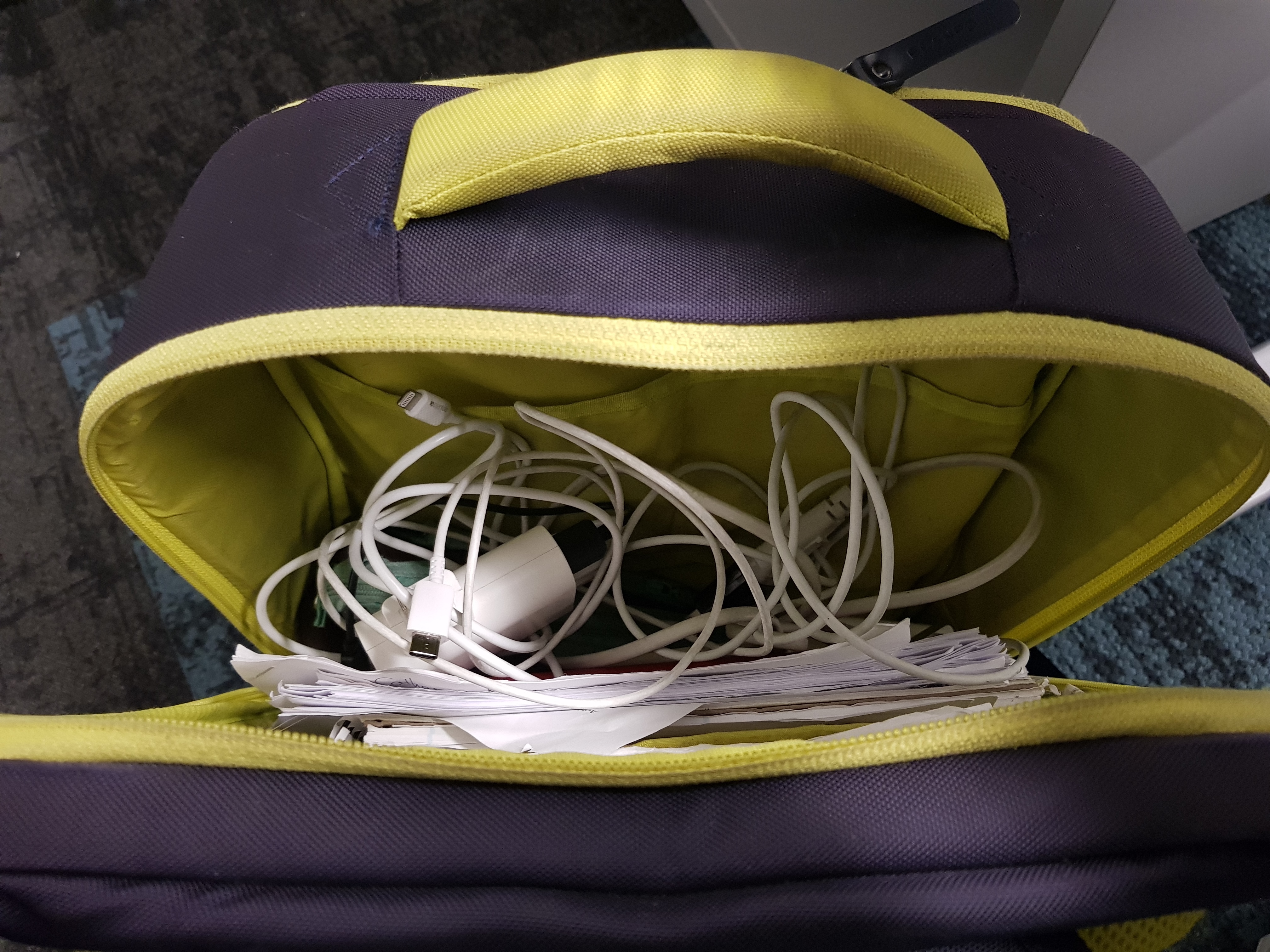
Chargers inside my backpack are all tangled up.
My initial idea was to create a small box in which I could organize all of my chargers inside. Since I had four wires, the idea was to have a RFID tag on each of the wires and have four RFID readers to sense that each wire has been placed in the right section of the box. The readers would look for the tag that they have been assigned to, and once they find the correct tag, they would turn on the LED on the outside and all I would need to grab would be the box with the LED lit up.
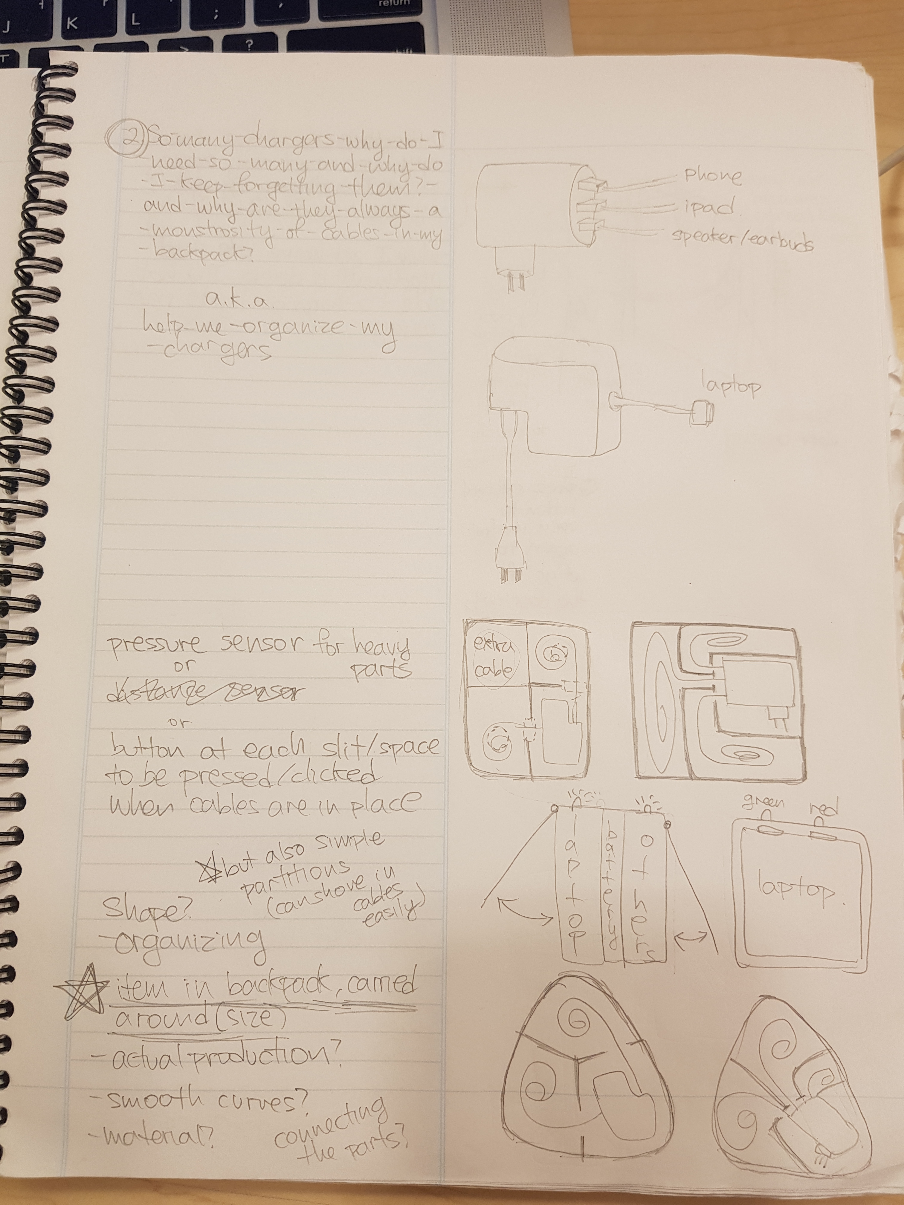
Initial idea for charger organizer box on the bottom right corner
It also involved exploring the RFID tags I could use, which ranged from cards and key fobs to little circular stickers.
But this seemed to be unnecessary and less rational at some point because if I had a box, all I would need to do is open it to check if I have all chargers. Plus, the smallest RFID tag I could find, the sticker, was still too large to put on a wire, which basically had no flat surface. The biggest problem I had to solve was if I always carry my chargers in my backpack, so creating another item that I potentially may forget to throw into my backpack seemed like it was not the ultimate solution. Thus, I had to come up with an alternative which would fundamentally tackle the situation.
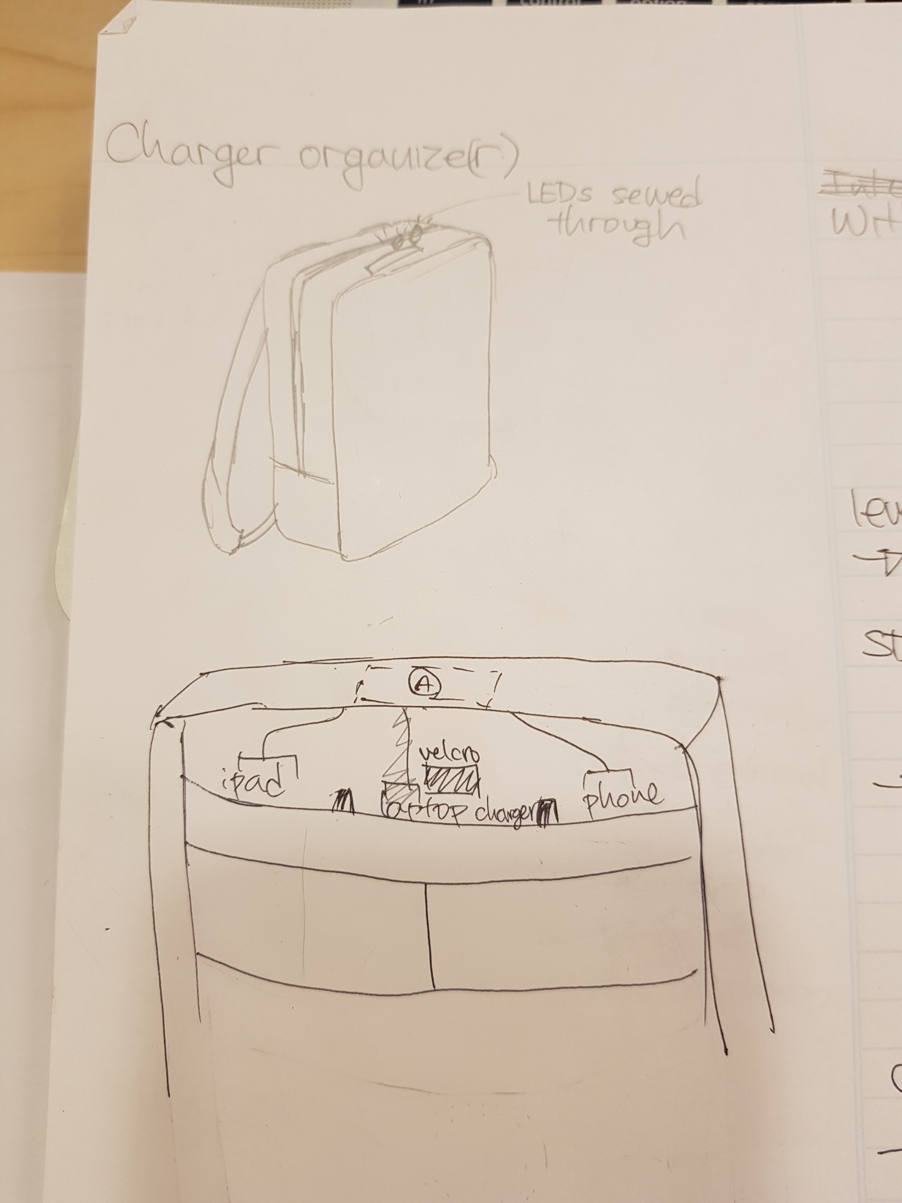
Electronics incorporated into backpack, initial sketch
A new iteration was to incorporate the electronics into my backpack. The core objective was to make my backpack know if it had all of my chargers. So all I had to do was make the RFID readers a part of the backpack and have LEDs poke out so that I can see it easily without opening it. I was able to convince myself that this was plausible because; 1. by pure luck I learned that I could pierce through the fabric of the zippers with the LED; 2. I had pockets in my backpack that I never used but was large just enough that I would have to really force myself to organize the wires before I put them in; and 3. my backpack has a rather stiff box shape which would make it easier to organize and attach the electronics and keep them in place.
For the electronics I went through the process of learning how RFID readers and tags work, learning how to connect two RFID readers to one Arduino Uno, learning what code is used with the RFID readers, and then adding two more readers. I also realized that I may have battery issues if the LEDs were on all the time, so I also added a force sensitive resistor to the bottom of the backpack that would initiate the entire program when the FSR would be pressed by the backpack, which means when it is put down on the ground, and would reset the entire program when there is no pressure on it. In the midst of this, I ran into multiple problems in every facet, which can be summarized to:
- The function dump_byte_array that was used in an example sketch was difficult to decipher and mold into the way I wanted to code to run. I tried multiple ways I could think of but it just simply did not give the output that I wanted it to. This was harder especially when I had two readers. I could already know that if I could not figure it out with two readers, I definitely would not be able to do it with four readers.
- Connecting four RFID readers and two controlled LEDs to one Arduino Uno board was rough. I was basically running out of pins. Even when I shared every pin that could be shared, I was using all of the digital pins with a bunch of wires, which would be difficult to organize in my backpack.
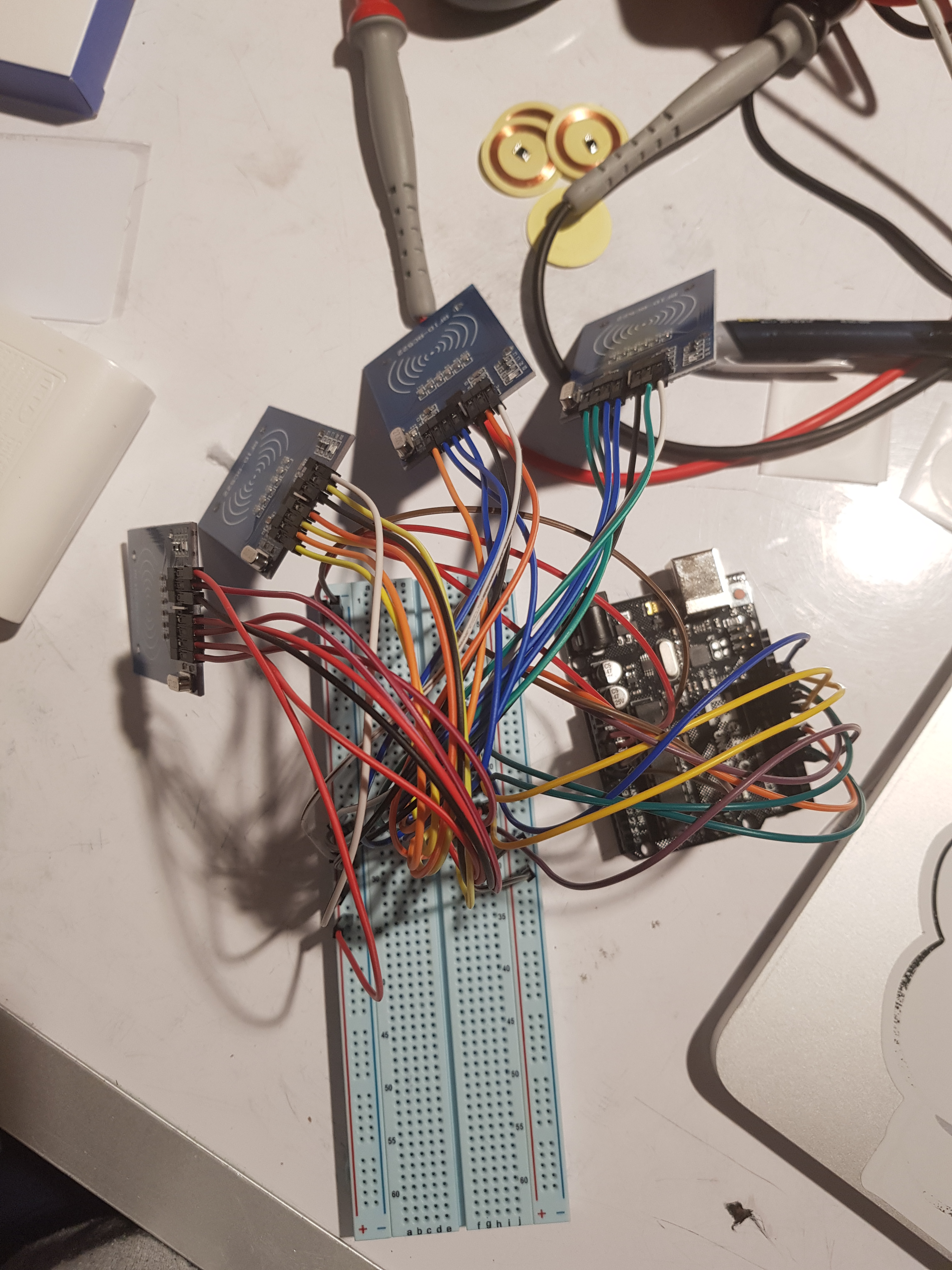
Four RFID readers involved lots of wires and lots of pins.
- Placing four RFID readers in my backpack also became an issue. My backpack has one big pocket and two smaller pockets, so I was planning to divide the big pocket and place one reader in each pocket, but that meant some readers could possibly overlap with each other, which sometimes made the entire electronics stop working.
- I still had the problem of putting a circular sticker on wires which had no big enough surface to put the sticker on.
To resolve this, I decided to stick to two RFID readers and two RFID tags only. One tag was put on my laptop charger and the other was put on an adaptor where I could plug all three of my chargers into one outlet. This simplified the electronics immensely and also solved the problem of placing an RFID tag on each charger.
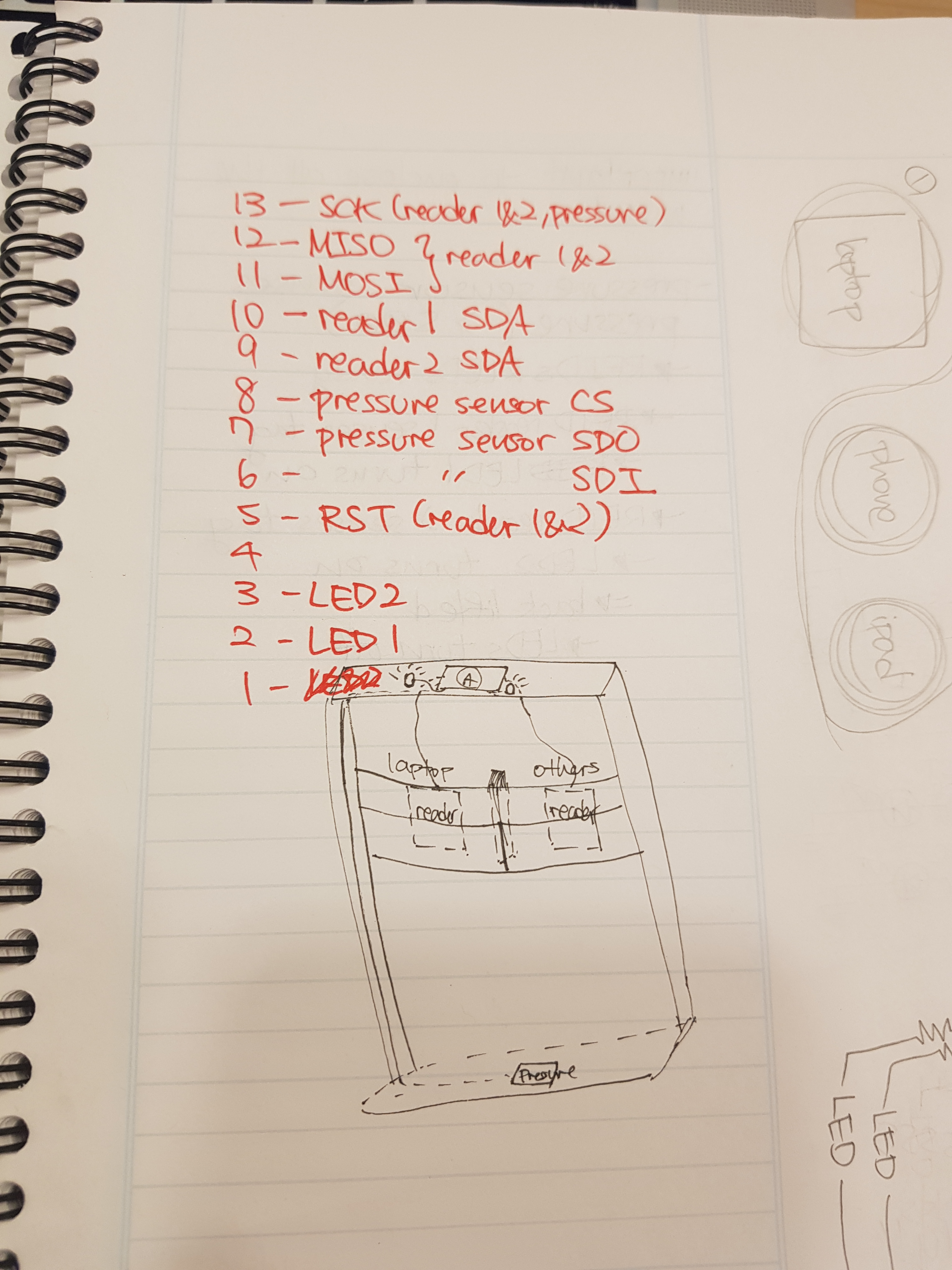
Refined sketch of two RFID readers and a pressure sensor on the bottom
Resolved to two RFID readers with two LEDs and an FSR
Discussion
As for the final product, I am proud of how I incorporated electronics into a pre-existing object but frustrated about the ‘finicky’ nature RFID readers. As I was planning and sketching for the final product, I did expect that I inevitably would have to solder electronics while they are inside my backpack, regardless of planning the wire plot as much as I can.
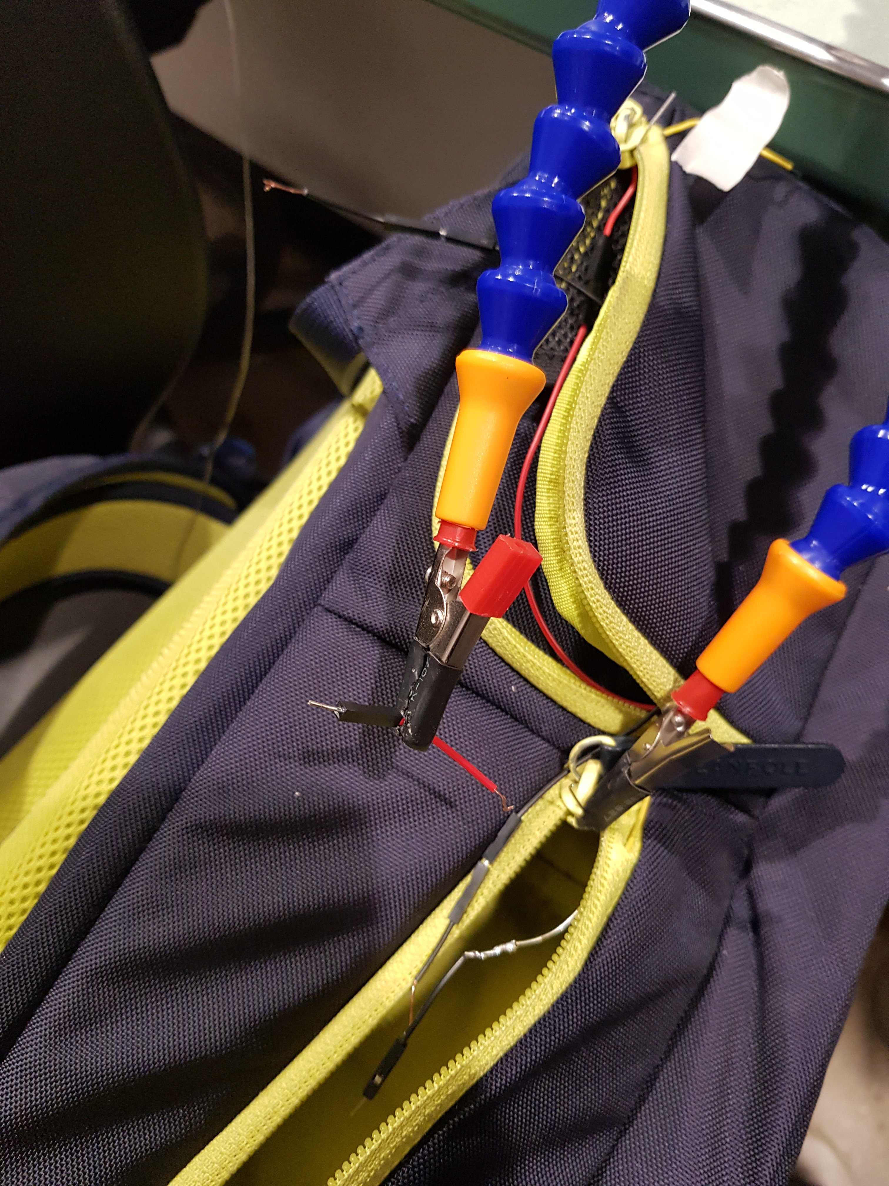
Soldering as wires are piercing through the backpack’s fabric
I definitely would allocate more time into soldering things because it took more time than I expected. I think I focused too much on the code, which was also difficult not to mention. The physical restraints of soldering very close to fabric or soldering in a smaller space were potentially dangerous (and I was very nervous about it too), but in the end I soldered everything into place without causing any hazards or resulting in any unconnected electronics. This success allowed my backpack, the project, to look really natural from the outside, and this specifically brought a lot of positive feedback such as; “Super minimalistic and subtle but still gets the job done!”, “From the outside your backpack looks normal, which is cool too”, and “really cool how you integrated it into the backpack and you can’t see any wires from the outside!” I’m particularly glad and proud that the majority of the feedback I received was about how it was integrated nicely into the object.
There also was a followup feedback about tidying the inside saying “maybe make wires on inside neater?” and “For very far off improvement, it would be cool if it was weather-proof. Since you put a lot of items inside your backpack, I’m worried about durability”, which I totally agree on. This falls into my initial wish of allocating more time into soldering and tidying up the insides. The wires in the current state do get in the way, so I would need to do a better job on sewing the wires more tightly and tucking them away to a corner.
For the frustration with the readers, I want to research more into it and find a way to fix it. The sad part for the critique was that it did not work, and I was tired of it. So, the RFID readers apparently would ‘get tired’ (as I like to call it) after a few runs of reading the tags. It would work perfectly as intended, but all of a sudden it would not respond. And when I ran the example code for using two readers, the serial feedback would say that communication failed and I would need to check the connection. The problem was odd because if I switched out the reader to a different one several times, then it was fine. When the new reader ‘got tired’ and I switched it back to the first reader I was using, it would work perfectly fine again. After I soldered everything the same problem happened, and this time it was much harder to switch out the readers because they were supposed to be tucked away inside the deep pocket. I really want to fix this part and make it work without any weird stops.
]]>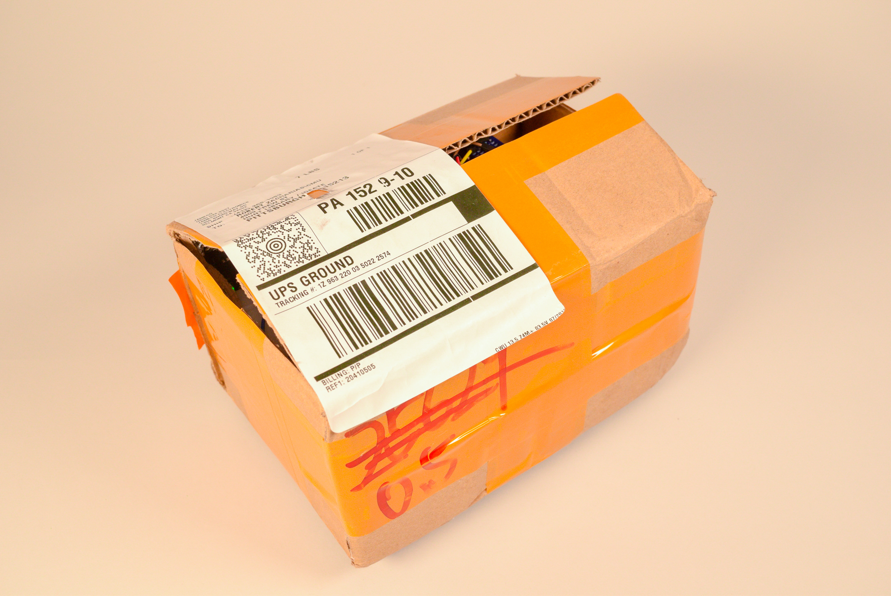
The appearance of moving courier box.
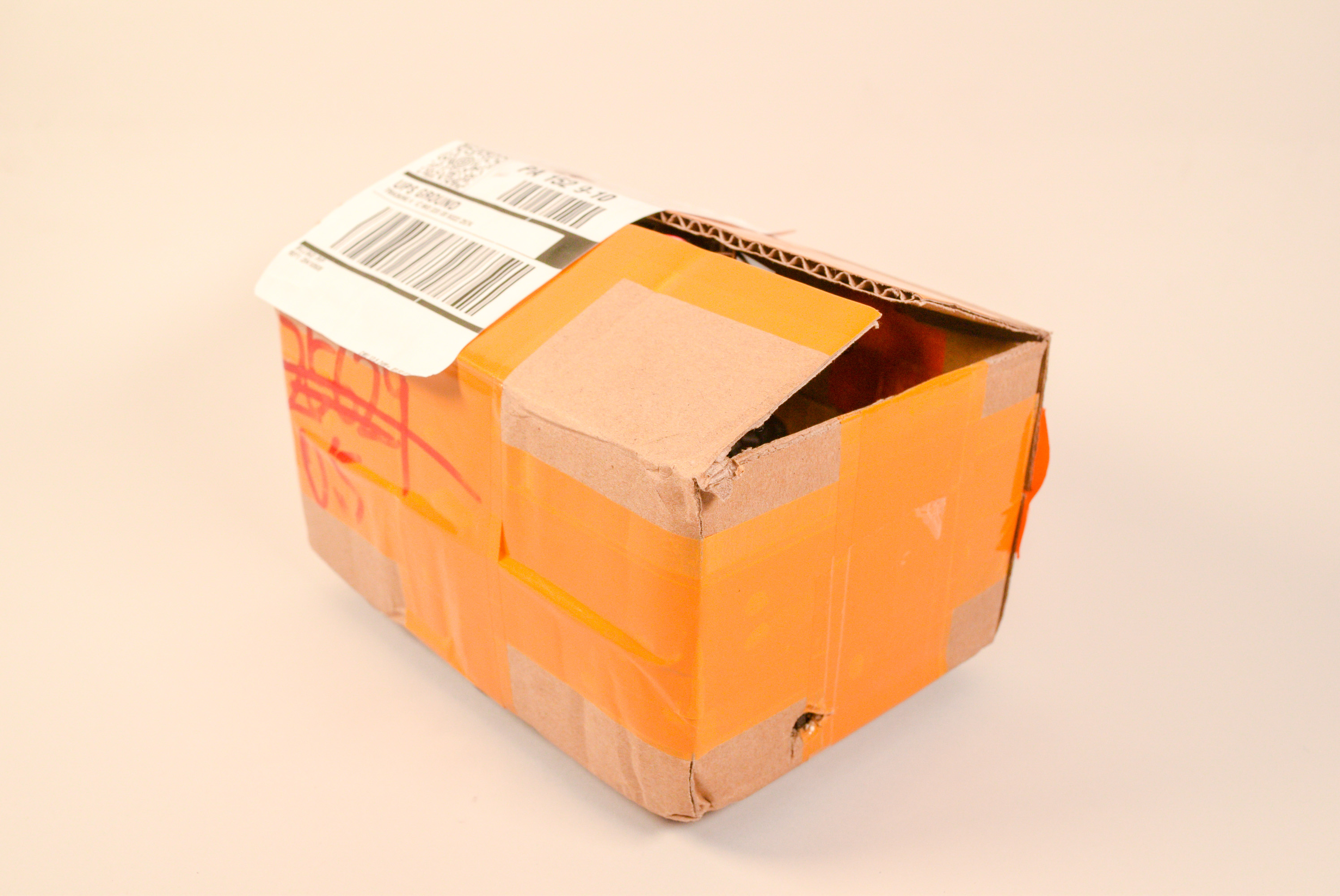
The appearance of moving courier box.
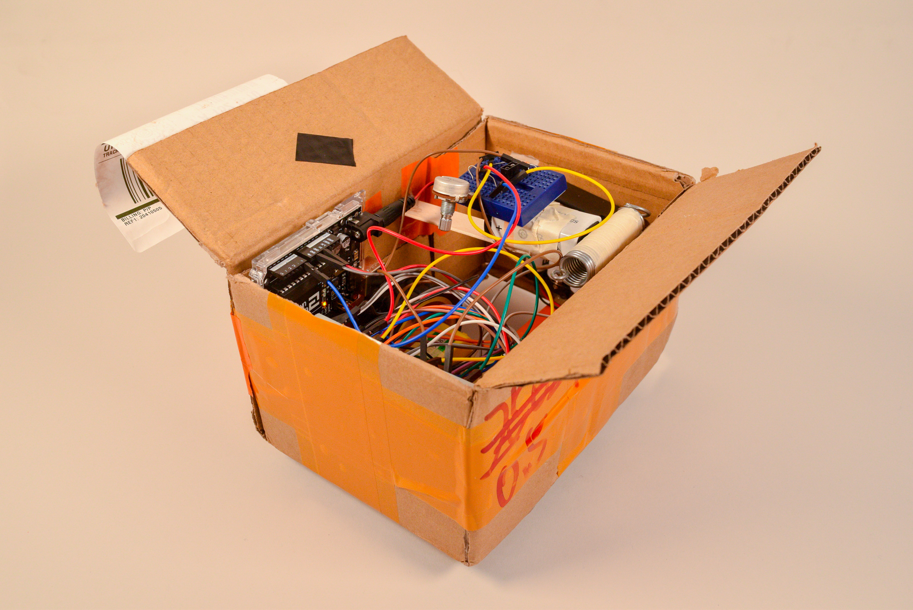
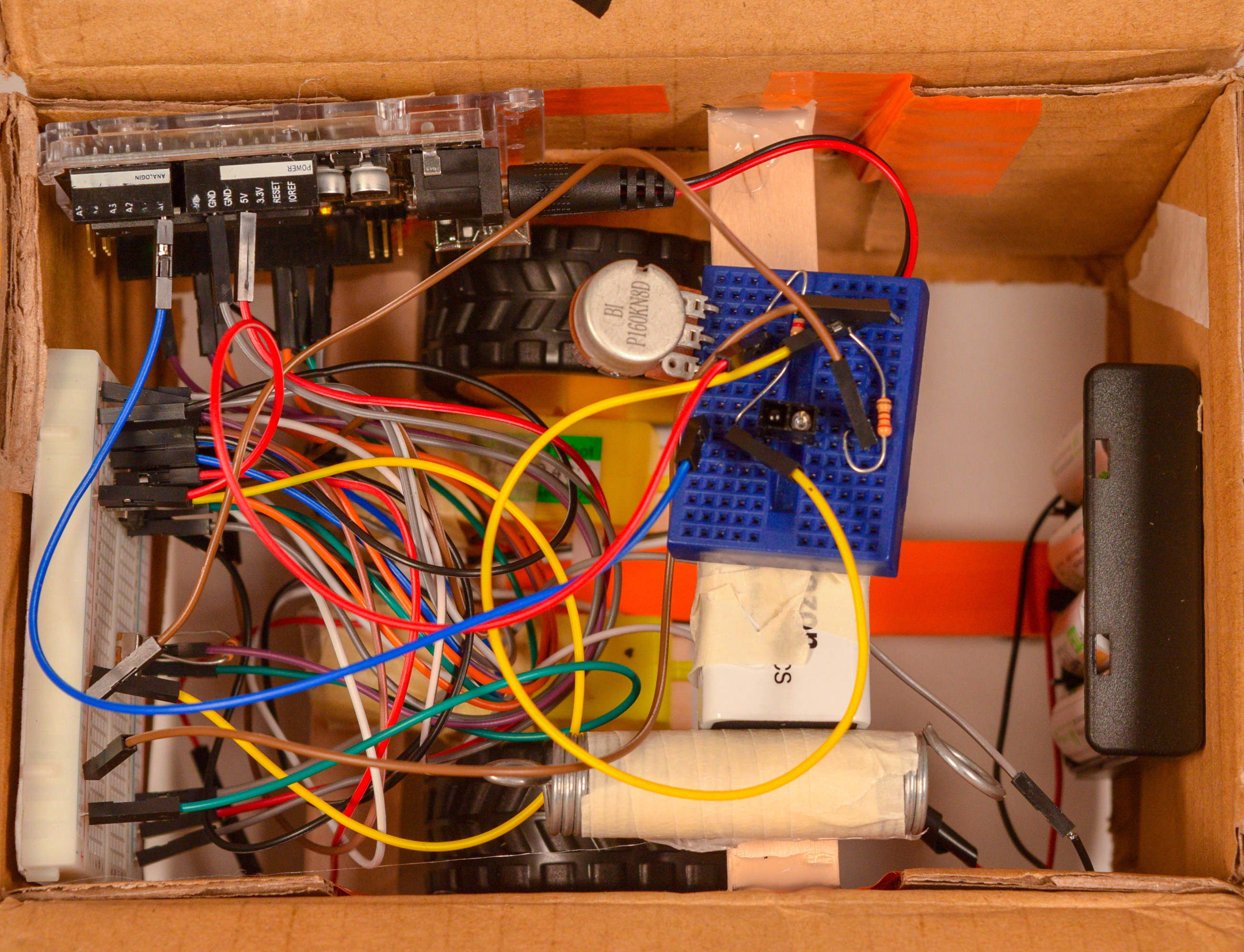
The internal structure of moving courier box.
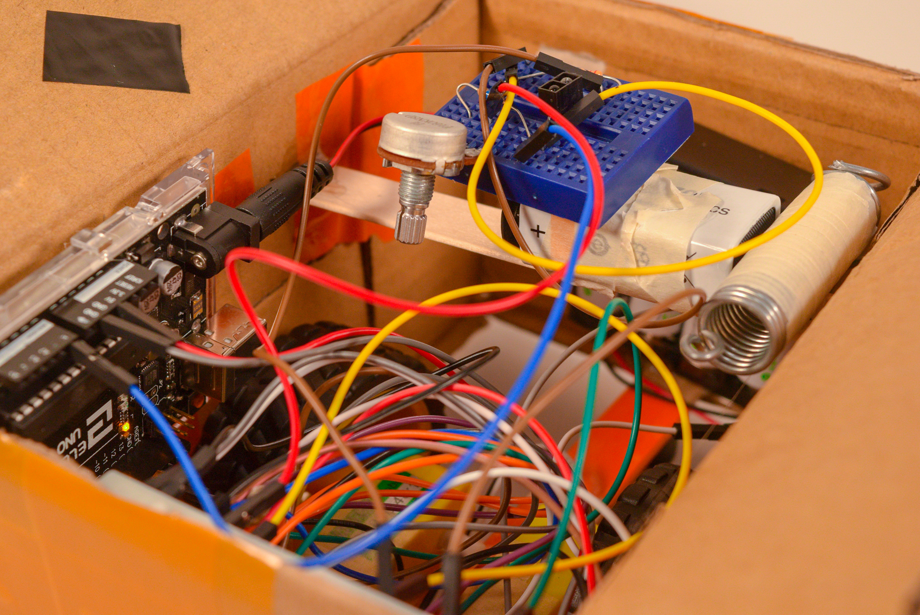
The internal structure of moving courier box.
The top view of moving courier box.
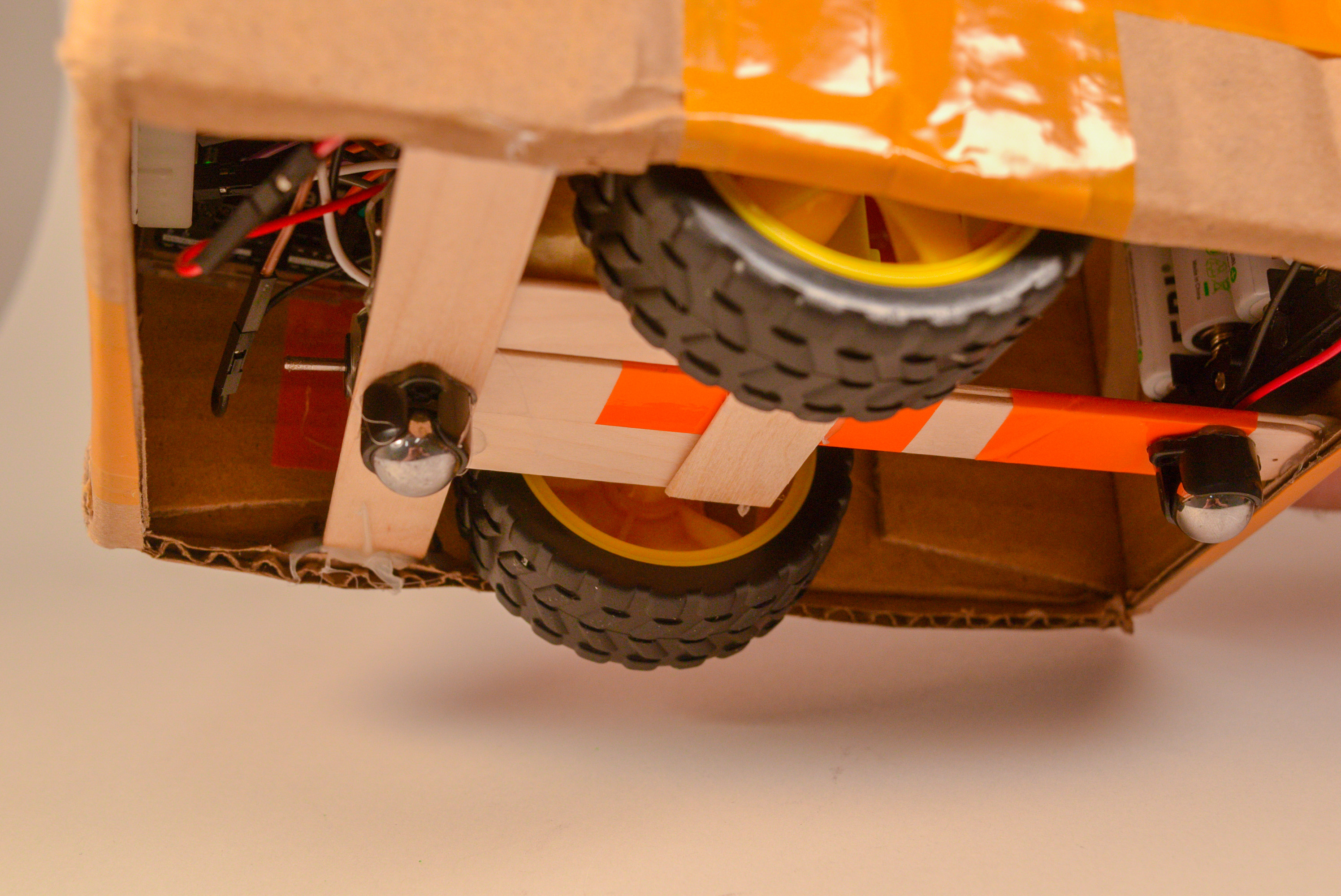
Bottom of moving courier box.
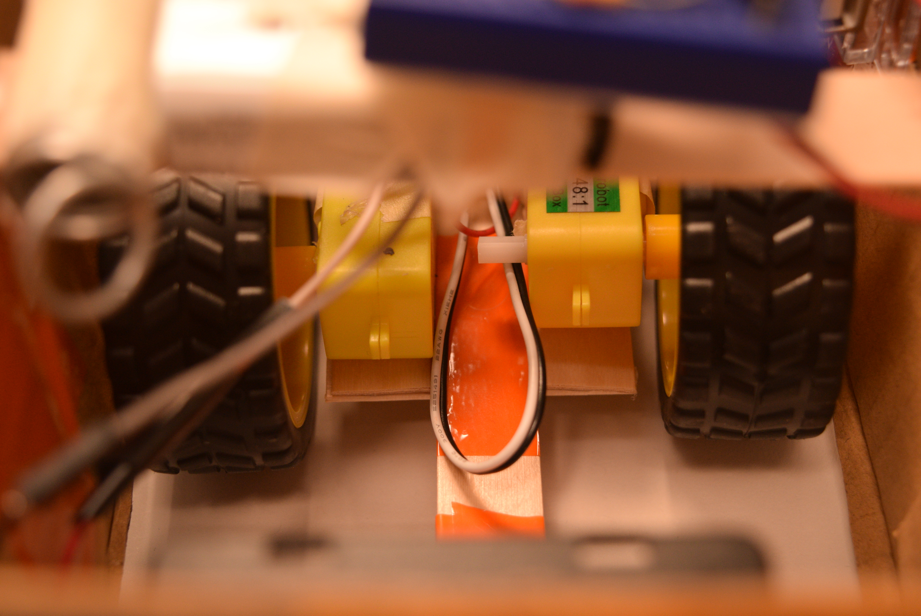
The driving motors and wheels of the moving courier box.
Narrative Description
The project was inspired by an Arduino project found online where a prank was done to people who were trying to get tissue from a tissue box. The tissue box would sense a hand is getting close and the box would move away from the approaching hand, not letting the person get the tissue. The aim of this project was similar, which was producing an object that would sense a human approaching and run away.
The object was intentionally chosen as an object that would be an everyday-item that people would expect to see at any place instead of an item specially made for this project. This induces the surprise of the project by making an object that people would not expect to move. Original ideas included chairs or tables in the lab, but because of physical constraints, the object was chosen to be a courier box.
progress images
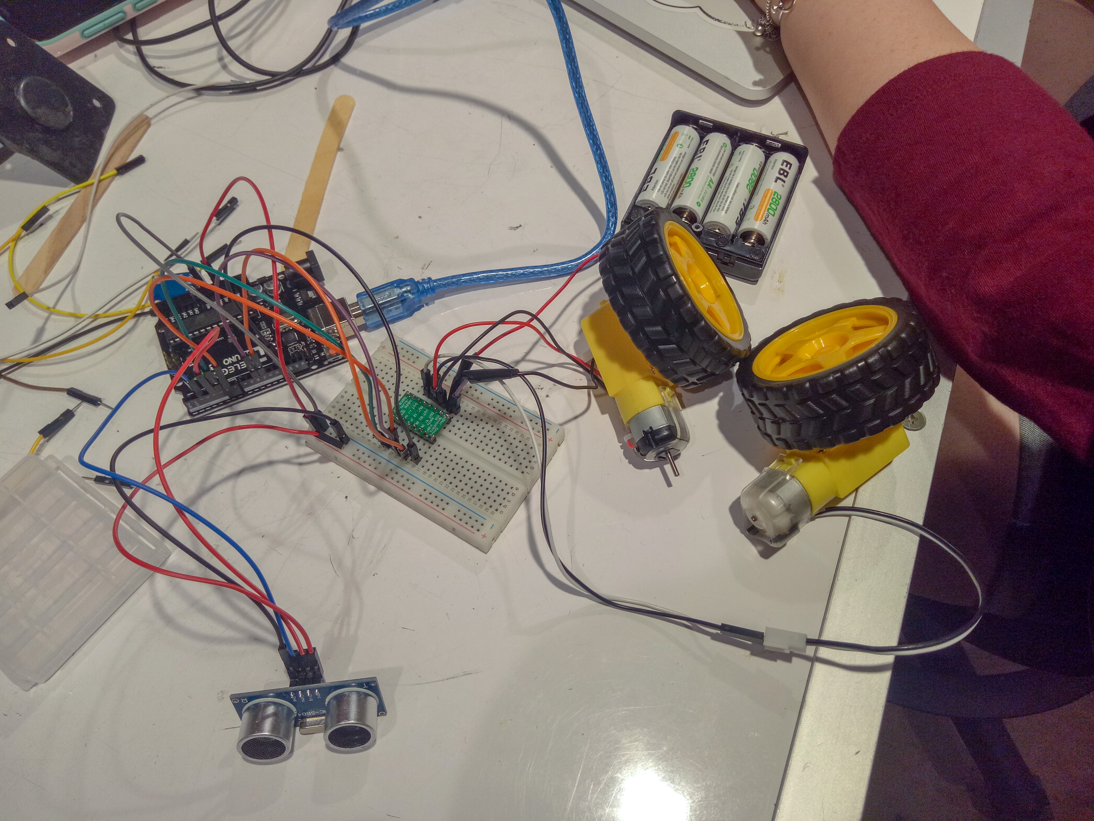
An ultrasonic ranger was used in our first attempt. However, it didn’t work well.
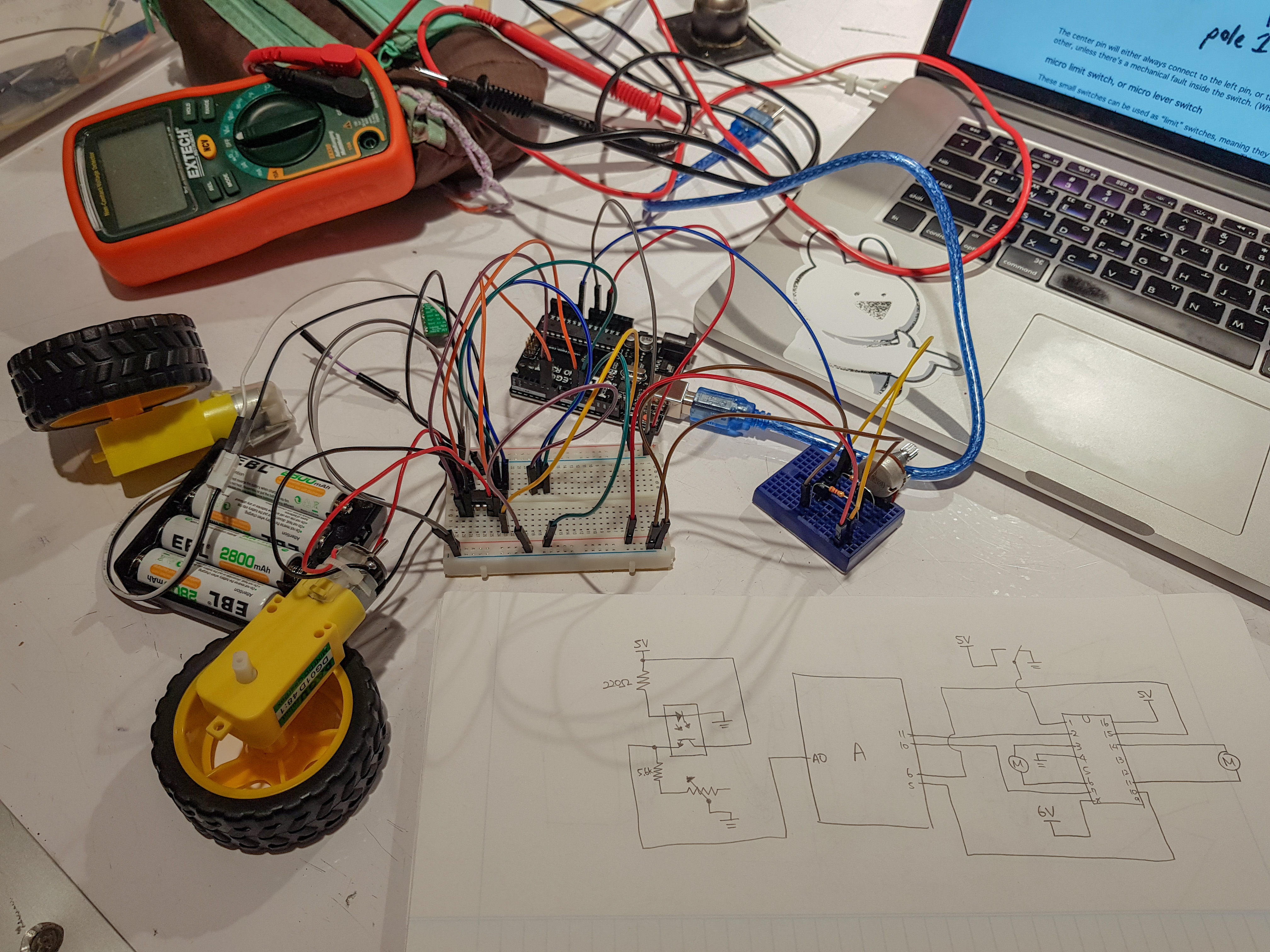
After several attempts, the IR sensor was selected since its good performance. The code and circuit parts were basically completed.
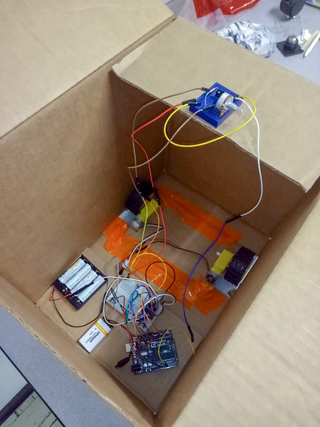
The power output of the motors was not enough to support the movement of the large box. Also, the bottom cardboard was bent due to the weight of the battery and other stuff. Therefore, we decided to change the size of the box.
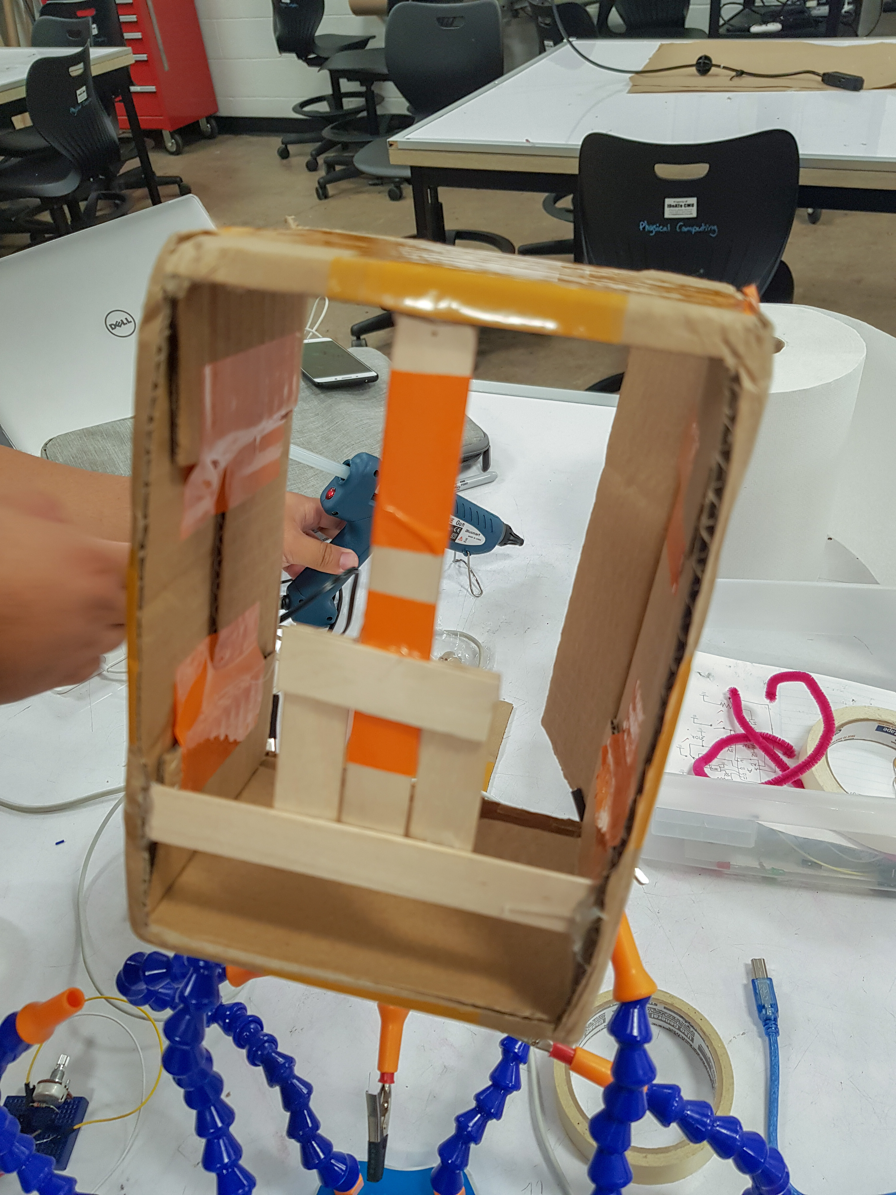
Having learned the lesson for the first time, we made the underside support structure out of wood to make sure the motors and wheels could work properly.
Discussion
Our initial concept was that once a hand approaches above the box in an attempt to open it, the box would sense the hand and run away from it in a random direction with random speed, using the random numbers that were generated by the Arduino.
Instead of the ultrasonic ranger that was introduced in class, an IR sensor has been used due to the instability of the data that the ultrasonic ranger gave and the smaller size of the IR sensor.
After the completion of the code and circuit parts, we tried to put it in a large cardboard box, but the power output of the motor was not enough to support the movement of the box. What’s more, the bottom cardboard was bent due to the weight of the battery and other stuff. Therefore, we had to choose a smaller courier box to achieve our initial goal.
The IR sensor’s unstable data and the physical installation of the electronics into the box resulted in a wobbly irregular movement of the box. It was not behaving perfectly as originally planned, but the mere appearance of a package box with a label moving around on a table still had a surprising element of an ordinary item moving as intended.
Schematic
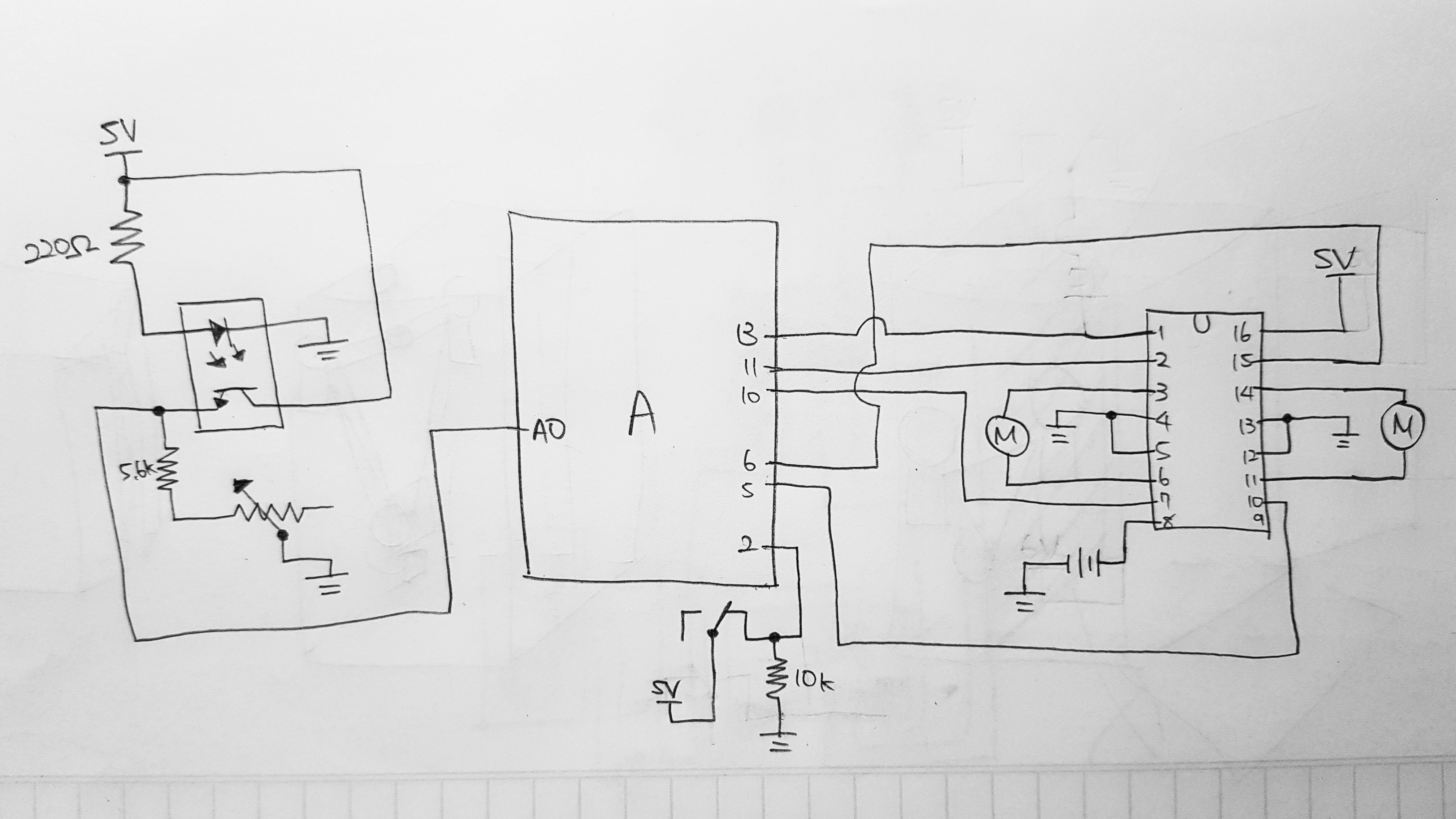
Schematic of the moving courier box
Code
//pin numbers

const int MOTORR1 = 6; //first pin for motor on the right

const int MOTORR2 = 5; //second pin for motor on the right

const int MOTORL1 = 10; //first pin for motor on the left

const int MOTORL2 = 11; //second pin for motor on the left

const int IRSENSOR = A0;

const int SWITCHPIN = 2;

const int DRIVERPIN = 13;

int direc;

int speedR;

int speedL;


void setup() {

  //Initialize pins

  pinMode(MOTORR1, OUTPUT);

  pinMode(MOTORR2, OUTPUT);

  pinMode(MOTORL1, OUTPUT);

  pinMode(MOTORL2, OUTPUT);

  pinMode(IRSENSOR, INPUT); //sensing distance

  pinMode(SWITCHPIN, INPUT); //decides whether to turn the driver on or off

  pinMode(DRIVERPIN, OUTPUT); //on/off will be delivered to driver

  //box will start not moving

  digitalWrite(MOTORR1, LOW);

  digitalWrite(MOTORR2, LOW);

  digitalWrite(MOTORL1, LOW);

  digitalWrite(MOTORL2, LOW);

  randomSeed(analogRead(0)); //don't plug anything into 0

  //Serial.begin(9600);

}


void loop() {

  //box will check if anything is too close

  int distance = analogRead(IRSENSOR);

  //Serial.println(distance);

  direc = random(2);

  speedR = random(255);

  speedL = random(255);

  int switchVal = digitalRead(SWITCHPIN);

  //driver turned on

  if (switchVal == HIGH) {

    digitalWrite(DRIVERPIN, HIGH);

    //maximum distance below is 50 for now, but it can be adjusted by wiggling the potentiometer

    //IR sensor will give low number when nothing is nearby and high number when something is close

    if (distance > 50 ) { //people are too close, so it wants to run away

      if (direc == 0) { //box moves forward

        //speed for motors will be different from each other

        //speed for each motor will be random so that the box will move at a random direction

        analogWrite(MOTORR1, speedR);

        analogWrite(MOTORR2, 0);

        analogWrite(MOTORL1, speedL);

        analogWrite(MOTORL2, 0);

        //Serial.println("forward,"+ String(speedR));

        delay(3000);

      }

      if (direc == 1) { //box moves backward

        analogWrite(MOTORR1, 0);

        analogWrite(MOTORR2, speedR);

        analogWrite(MOTORL1, 0);

        analogWrite(MOTORL2, speedL);

        //Serial.println("backward");

        delay(3000);

      }

    }

    else {

      digitalWrite(MOTORR1, LOW);

      digitalWrite(MOTORR2, LOW);

      digitalWrite(MOTORL1, LOW);

      digitalWrite(MOTORL2, LOW);

    }

  }

  else {

    digitalWrite(DRIVERPIN, LOW);

    //Serial.println("driver off");

  }

}
if (direc == 0) { //box moves forward
//speed for motors will be different from each other
//speed for each motor will be random so that the box will move at a random direction
analogWrite(MOTORR1, speedR);
analogWrite(MOTORR2, 0);
analogWrite(MOTORL1, speedL);
analogWrite(MOTORL2, 0);
//Serial.println("forward,"+ String(speedR));
delay(3000);
}
if (direc == 1) { //box moves backward
analogWrite(MOTORR1, 0);
analogWrite(MOTORR2, speedR);
analogWrite(MOTORL1, 0);
analogWrite(MOTORL2, speedL);
//Serial.println("backward");
delay(3000);
}
}
else {
digitalWrite(MOTORR1, LOW);
digitalWrite(MOTORR2, LOW);
digitalWrite(MOTORL1, LOW);
digitalWrite(MOTORL2, LOW);
}
}
else {
digitalWrite(DRIVERPIN, LOW);
//Serial.println("driver off");
}
}
Author
]]>Short description: This person created a split-flap display that shows the weather including the temperature and conditions using abbreviations on the display based on the weather information from the Internet using Wi-Fi and a weather API app.
My response: I like this project and actually I’d like to have one because I always check the weather in the morning and when I’m in a hurry, even checking my phone (unlocking it, going through the weather app, waiting for it to connect) takes precious time. With this display, it would automatically show the weather like a calendar.
I would, though, wish it would show the weather conditions with diagrams instead of the abbreviations the creator made because it would be more intuitive to understand for people who, for instance, buy it. Abbreviations would be useful for the creator because he or she came up with it, but for people who use it the first time, they would have to learn the abbreviations first.
]]>