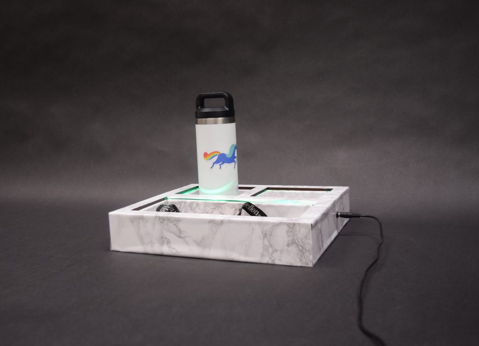
It’s happened to everyone: we misplaced our keys again, left our water bottle behind, forgot our student ID in our dorm. The Forget-Me-Not tray is the one-stop storage for all your important daily essentials. Not only does this centralize a location for all your daily items, the Forget-Me-Not tray uses subtle LED lights to remind you whether you’ve placed your items inside the tray or not.
The Product
This tray features three comfortably-sized compartments that can house small-to-medium sized items that you can’t leave the house without.

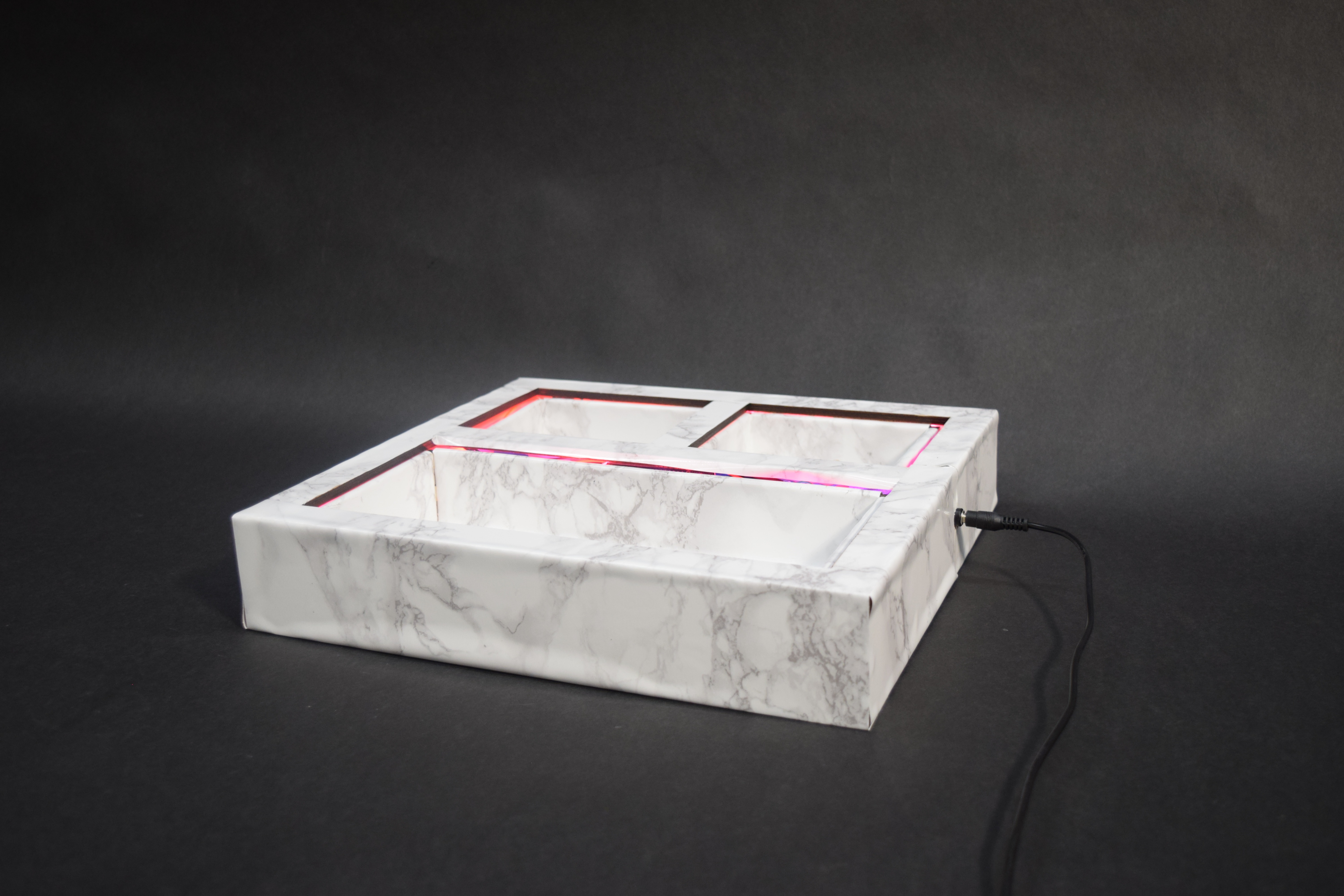
The tray’s LED lights are powered by a single 5V power supply. I laser cut a hole into the tray to fit a detachable outlet for this power supply. This offers the user flexibility in case they’d like to turn the LED lights off for bed.
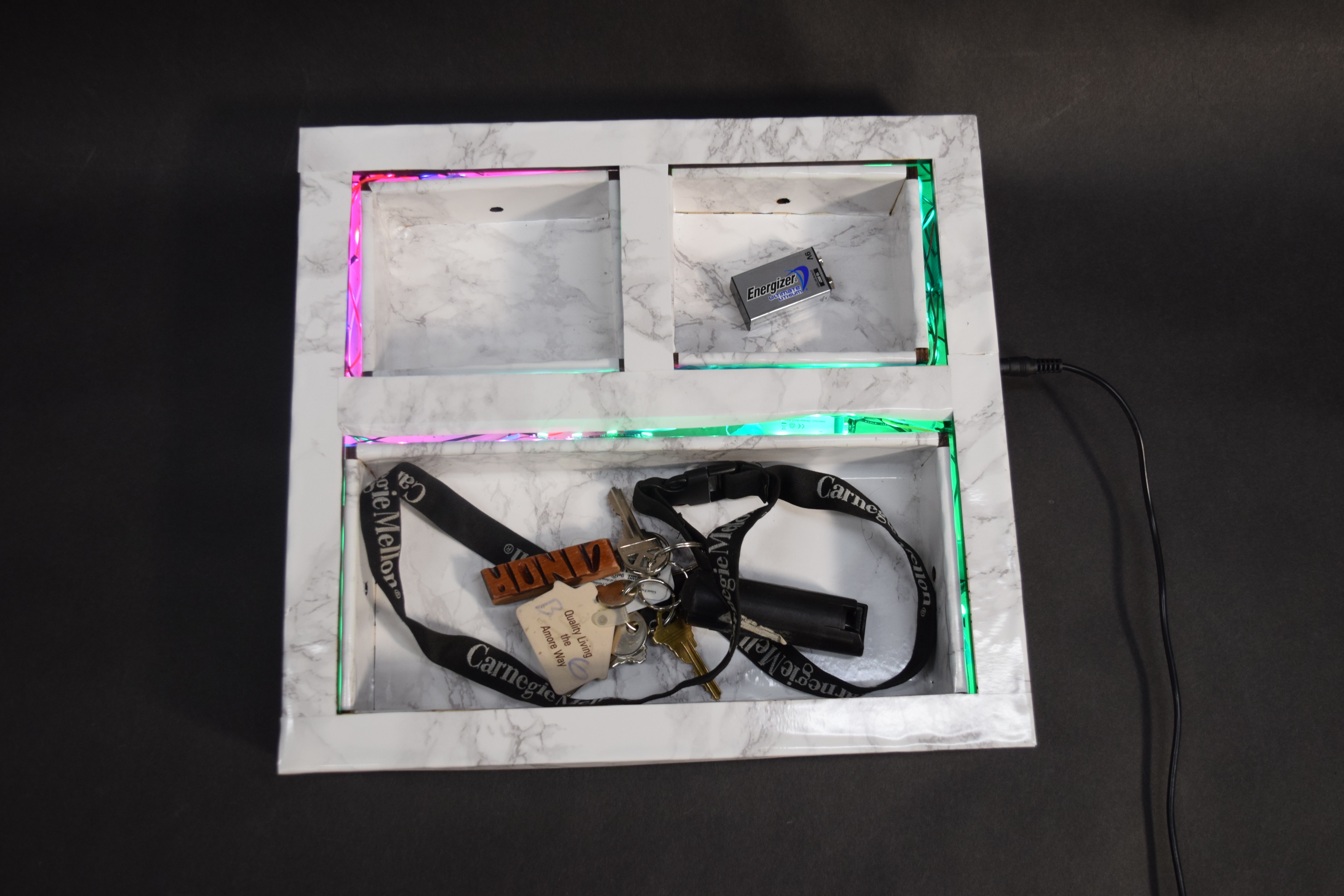
A bird’s eye view of the tray when two of its three compartments have items in them. Once an item is placed inside the tray, the LED lights will switch from pink to green.
I laser cut holes into each compartment where three sets of breakbeam sensors were located. Each set included an emitter, which would send out a beam of human-invisible infrared light, and a receiver. Once items were placed inside the compartment, it would break beam of light. I used this signal to tell the Arduino which color to program the LED lights.
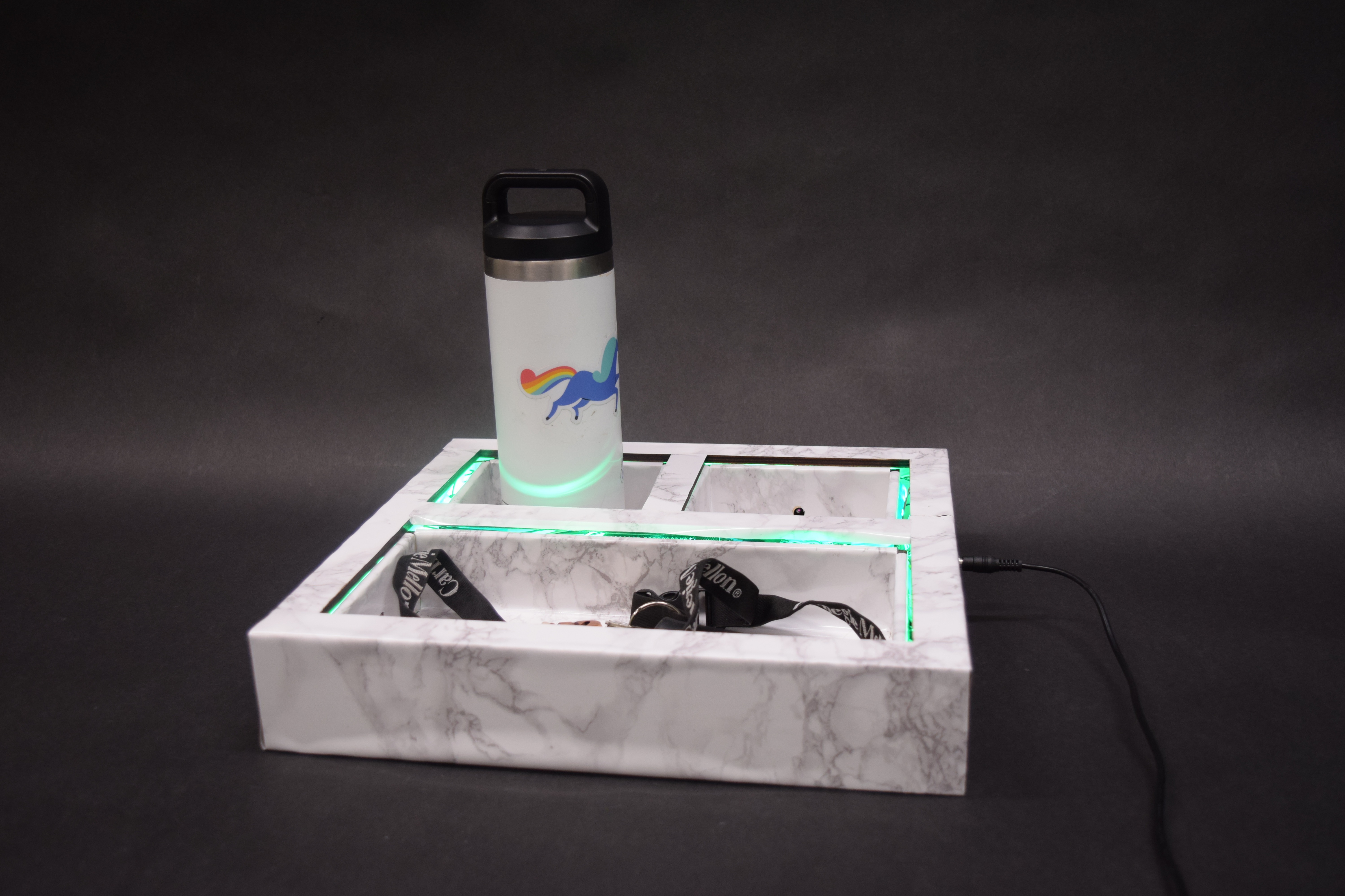
Lastly, the aesthetic appeal of the tray was important to me. This meant hiding the internal wiring, including the Arduino, and covering the plywood grain with a roll of white marble contact paper I got from Amazon to give it a polished look.
My keys are probably the most important item that I can’t forget when walking out my door (otherwise I’ll be locked out!). This tray is the place where I’ll be reminded to put them in a safe spot so I can start my day worry-free.
The Process
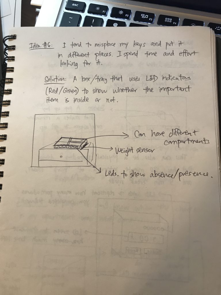
This was my original brainstorm sheet with my problems statement and my proposed solution. It was straightforward, and none of the major parameters changed from the brainstorming to execution stage (which I think is quite rare for a project, but perhaps meant that this project was in scope). Originally, I wanted to put large LEDs on the border of the box to display whether or not an item was inside or not, but eventually pivoted when I realized that perhaps it would be too bright and distracting as an everyday object.
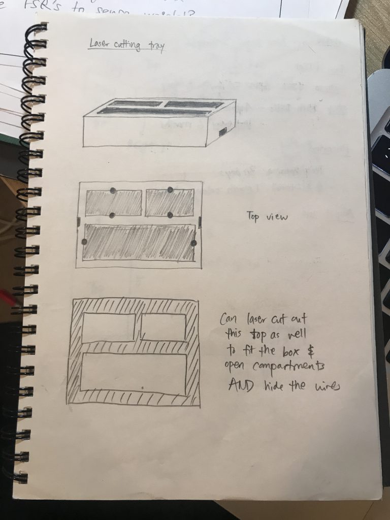
I bounced my ideas of laser cutting a tray off a few of my classmates and Zach, and they helped guide me to an idea of laser cutting three separate boxes, with one very large box to contain them both. This seemed pretty ambitious to me, since I had 0 laser cutting experience prior to this project. But with the time and curiosity I had, I decided to try it out, as it was my best shot of creating a completely enclosed, “wireless” Arduino project.
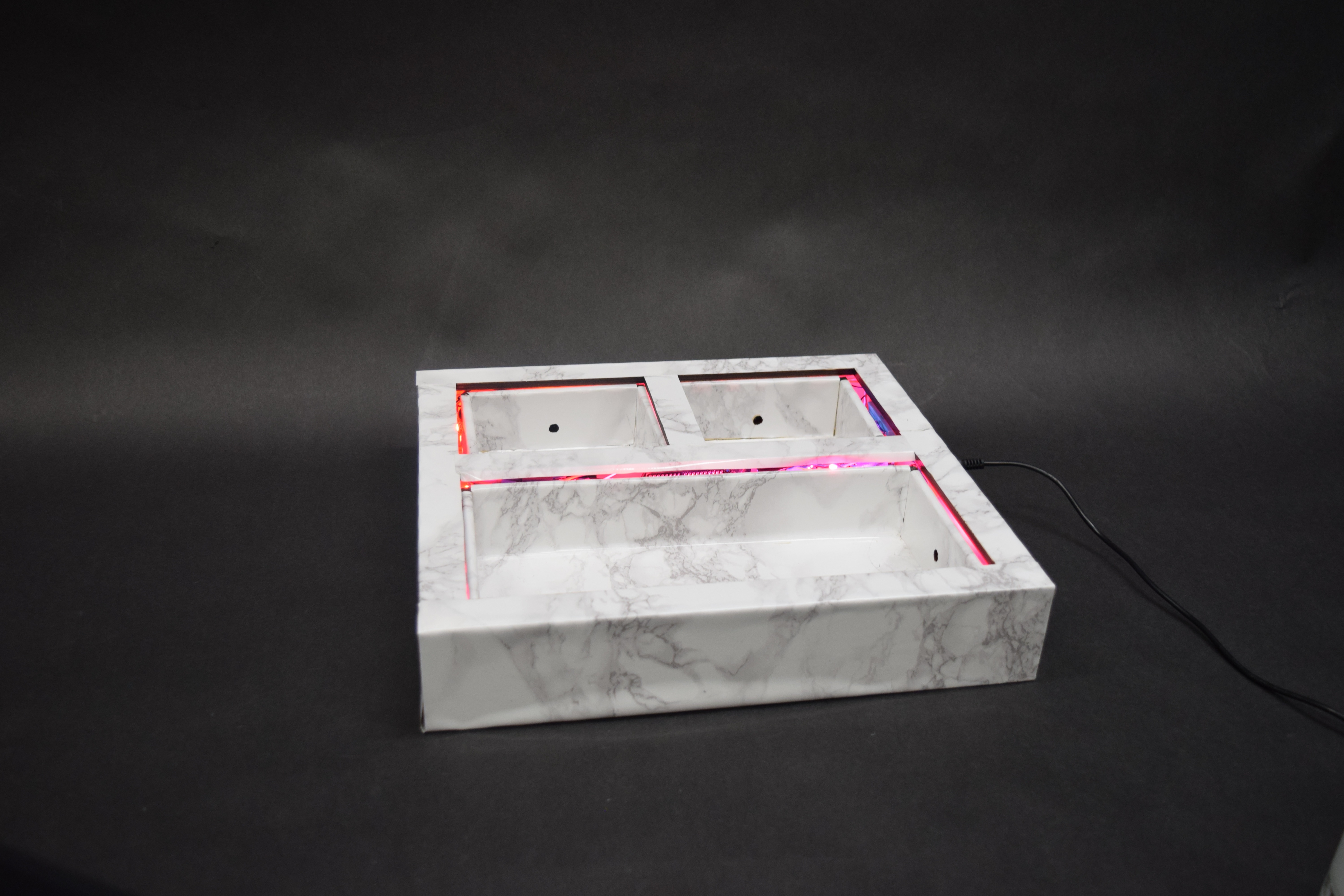
Once I created my first laser cut prototype of three boxes, hot-glued the pieces together, and placed them into the larger laser cut tray, I noticed that the compartment-sized boxes that I cut out of my tray top were too small for the compartments. So, I decided to go back and laser cut larger compartment windows on the tray top. This time, I accidentally cut them slightly too large, but I realized that it could actually provide an avenue of subtle light, if I placed the LEDs within the internal rivers of the tray.
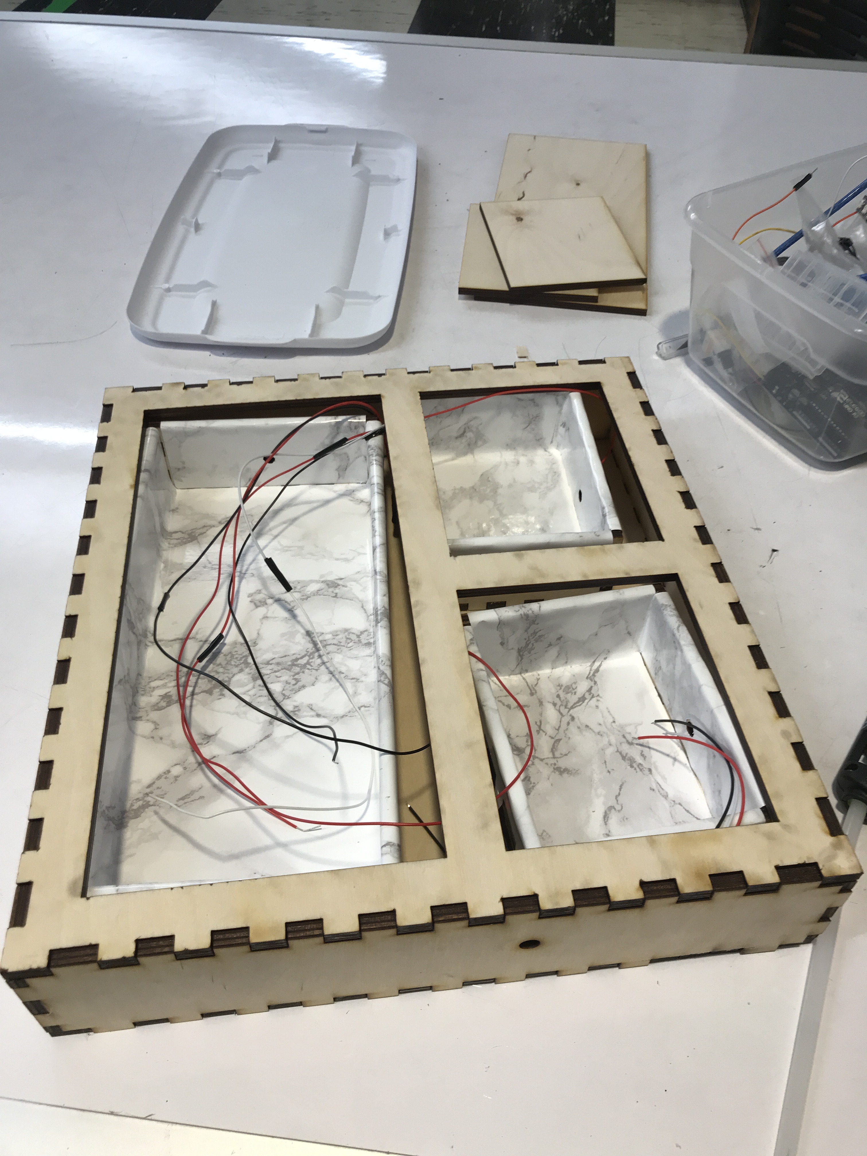
As you can see, the tray top has compartment holes that are slightly too large for the three boxes inside the tray. I decided to use this to my advantage, and install the LED strips along the border of these inside boxes. Originally, I wanted to install the LED strips along the outside of the tray, but realized that this was a great instance of “It’s a feature, not a bug” and put the LED strips inside the tray for a more subtle, glowy lighting effect. Additionally, since this presentation of the project was important to me, I decided that I wanted to somehow cover the burn marks that the laser cutter made on the plywood. Luckily, I’ve been into a DIY phase while watching YouTube and came across the concept of contact paper. This helped brighten and polish the tray’s look immediately, and it got a lot of positive feedback and gasps (“is that real marble?”).
While the functionality is simple and straightforward (remember to put your items in one place), many many hours were invested into this project. Despite a number of roadblocks, I was able to finish this project in time for the in-class demo, where I received quite a few interesting suggestions from my peers as feedback.
One of my classmates noted that it would be even more functional if I could specify the items that could be inside each compartment, so that it could enforce a stricter sense of accountability and precision with what important items should not be forgotten. I had considered the idea of using RFID tags, which could extend the ability for custom objects to be recognized, but I preferred not to place an identifying RFID tag on each of my objects, since the objects I intended to put inside (e.g. my keys, my water bottle, my wallet) experience a lot of wear-and-tear, and the tag might eventually fall off. Another student suggested that the items could be identified specifically using FSRs to sense weight, which I thought could be a promising lead, but would require a degree of precision. This is definitely a route that I could explore deeper to help make the tray even “smarter.”
Another particularly interesting suggestion a classmate had was adding more feedback to reinforce the “learning” to place things inside the tray. I hadn’t considered using alternative methods of feedback, like haptic feedback or even a sound alert. While I think haptic feedback might not be appropriate given the size of the tray (it can’t be handheld), I could have explored further with gentle sound feedback that can increase sensory associations (like a beep on a checkout machine) and improve accountability.
Overall, I feel happy with my project. My learning goals for this assignment were to 1) try out a completely new sensor that hasn’t been talked about in class, and 2) focus on polishing the presentation of the project, specifically with laser cutting, which I hadn’t done before and wanted to learn. I think I’ve been able to achieve these two learning goals for the most part; my project’s technical aspects work very reliably, and I was able to hide all the internal wiring inside the tray. I also feel pleased that I scoped this project well, recognizing when I should focus on debugging rather than continuing to develop more features. If I had more time, I would have loved to develop this project more technically, adding on more predictive sensors like my classmates suggested.
The challenges of this project for me were less technical, and more mechanical. I was able to get a MVP working by scrapping together an old Amazon box and punching out holes for the breakbeam sensors to peep through.
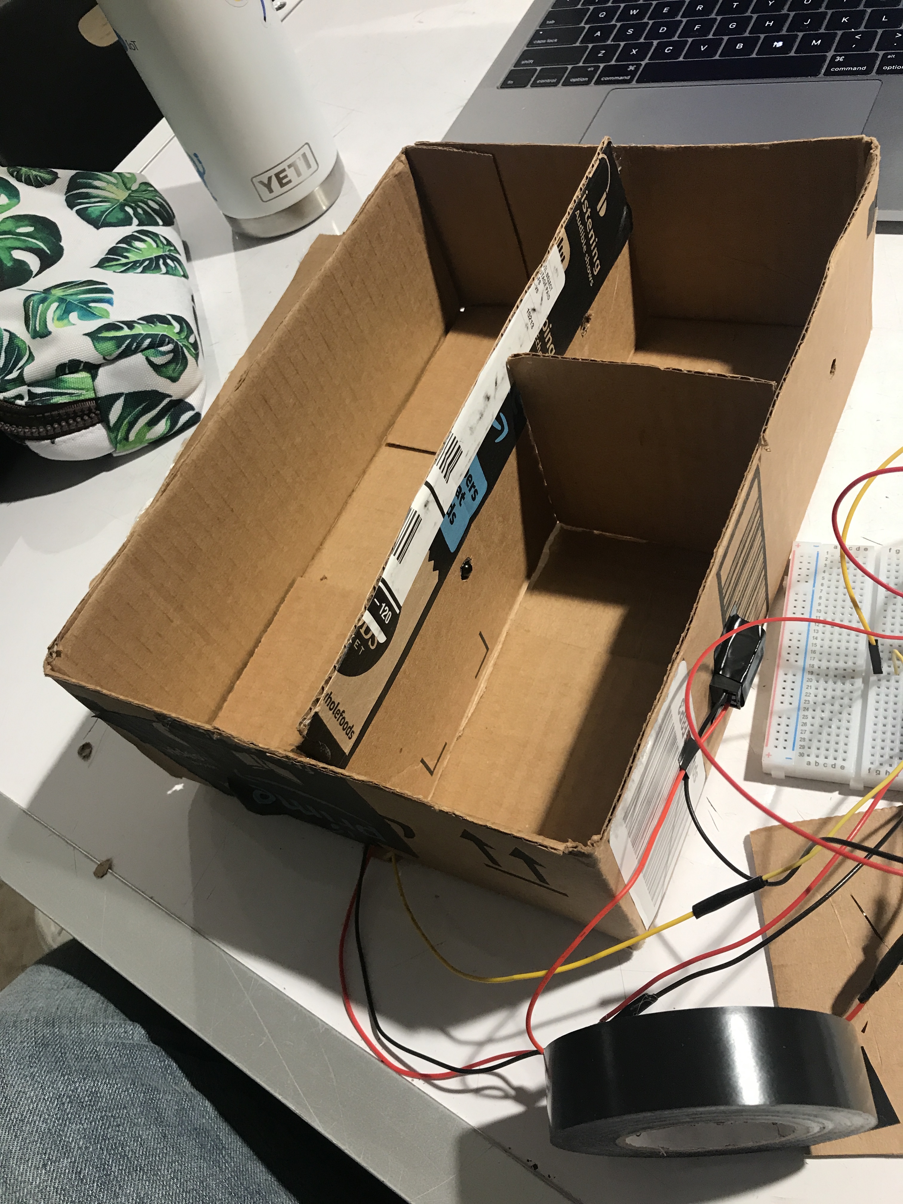
MVP of the tray with a scrappy Amazon cardboard box, with a first set of breakbeam sensors installed.
Once I got one pair of sensors working with deployed code on my Arduino, I focused on learning how to laser cut. This involved a week-long journey of asking my friends in IDEATE/Mechanical engineering how to navigate laser-cutting software, finally being able to cut out my tray, only to find out that the measurements were off, and so on. During my third time cutting this tray during open fabrication hours, I told the supervisor on duty that I’d been trying to cut this tray a number of times. I felt ready to be “hacky” and use an uneven frame with an Arduino that wouldn’t really fit. But I was told that it was part of the process, and seeing other students filter into the room, ambitiously and studiously cutting their own projects, gave me the spark that I needed to laser cut a perfect and even fourth tray. Seeing the tray finally come together, with the correct holes for the power supply and breakbeam sensors, with enough space to fit the Ardunio, was extremely gratifying, and I learned that it really does take many iterations to get a physical prototype right. Also, patience is indeed a virtue.
In the future, I’d love to further develop this project, but probably not on the same tray; I’d start from scratch. One issue with my tray was that there was barely enough space between the compartments to fit all the wiring (which surprised me, as I thought 1-inch margins were quite generous). I would laser cut the tray with larger margins for ample wiring space, and also use non-reflective aluminum foil paper to create a light barrier between each compartment, such that the different LED lights don’t blend together. I would also take my time to do a few iterations on cheaper material, like cardboard, so I have a better sense of the size/proportions of the prototype, and save time fixing mistakes that could’ve been recognized earlier on (for example, the holes I initially laser cut for my breakbeam sensors were too high off the ground, and didn’t recognize every object placed in the compartment).
Schematic
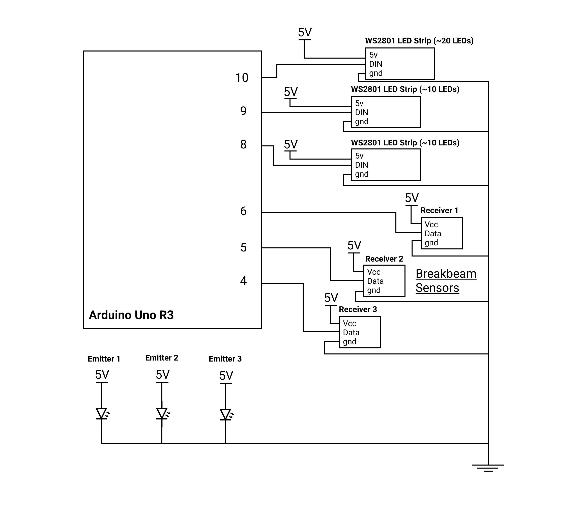
Electrical schematic of Forget-Me-Not Tray.
- /*
- * Linda Xia
- * 60-223 Physical Computing
- * Title: Forget-me-not Tray
- *
- * Description: This code is pretty straightforward. It uses the Adafruit NeoPixel library in order to power the three LED strips (WS2801), which
- * are situated on the outside of each of the three trays. Each of the three trays has a breakbeam sensor hidden in the walls. This code indicates
- * that once any of the breakbeam sensors indicate that there is a Very Important Thing (VIT) is placed in the tray, then the appropriate LED strip
- * for that tray will turn from an alarming red to comfortable green. Suggested pins for breakbeam sensors and LED strips are below.
- *
- * I drew from two examples: 1) Adafruit NeoPixel Library - simple, and 2) https://learn.adafruit.com/ir-breakbeam-sensors/arduino.
- *
- *
- *
- */
- #include <Adafruit_NeoPixel.h>
- #ifdef __AVR__
- #include <avr/power.h>
- #endif
- /* ARDUINO LED PIN */
- #define LEDPIN 13
- /* BREAKBEAM SENSOR PINS */
- #define A_BREAKBEAM_PIN 4
- #define B_BREAKBEAM_PIN 5
- #define C_BREAKBEAM_PIN 6
- /* LED STRIP PINS */
- #define PIN 10
- #define PIN_B 8
- #define PIN_C 9
- /* Defines the number of NeoPixels attached to the Arduino */
- #define NUMPIXELS 50
- /* When we setup the NeoPixel library, we tell it how many pixels, and which pin to use to send signals.*/
- Adafruit_NeoPixel pixels = Adafruit_NeoPixel(NUMPIXELS, PIN, NEO_GRB + NEO_KHZ800);
- Adafruit_NeoPixel pixelsB = Adafruit_NeoPixel(NUMPIXELS, PIN_B, NEO_GRB + NEO_KHZ800);
- Adafruit_NeoPixel pixelsC = Adafruit_NeoPixel(NUMPIXELS, PIN_C, NEO_GRB + NEO_KHZ800);
- int sensorState = 0;
- int sensorStateB = 0;
- int sensorStateC = 0;
- int lastState = 0;
- int lastStateB = 0;
- int lastStateC = 0;
- int delayval = 500;
- void setup() {
- /* Initializes LED Pin on Arduino for debugging output of breakbeam sensors.*/
- pinMode(LEDPIN, OUTPUT);
- /* Initialize the sensor pin as an input */
- pinMode(A_BREAKBEAM_PIN, INPUT);
- digitalWrite(A_BREAKBEAM_PIN, HIGH); // turn on the pullup
- pinMode(B_BREAKBEAM_PIN, INPUT);
- digitalWrite(B_BREAKBEAM_PIN, HIGH); // turn on the pullup
- pinMode(C_BREAKBEAM_PIN, INPUT);
- digitalWrite(C_BREAKBEAM_PIN, HIGH); // turn on the pullup
- Serial.begin(9600);
- // This initializes the NeoPixel library.
- pixels.begin();
- pixelsB.begin();
- pixelsC.begin();
- }
- void loop(){
- /* Reads the state of the breakbeam sensor value: */
- sensorState = digitalRead(A_BREAKBEAM_PIN);
- sensorStateB = digitalRead(B_BREAKBEAM_PIN);
- sensorStateC = digitalRead(C_BREAKBEAM_PIN);
- /* If the sensor beam is broken (sensorState == LOW), then write to the LED on the Arduino for debugging output. */
- if (sensorState == LOW || sensorStateB == LOW || sensorStateC == LOW) {
- digitalWrite(LEDPIN, HIGH);
- }
- else {
- digitalWrite(LEDPIN, LOW);
- }
- /*
- * If the sensorState value is HIGH for any of the break, then the IR beam in the breakbeam sensor hasn't been broken and an object hasn't
- * been placed inside the tray. Therefore, the tray color remains an alarming red and signals to the user: "HEY. You forgot to put your VIT (Very Important Thing) in your
- Forget-me-not Tray!"
- Also, the previous state (lastState) has to be different from the current state in order to detect a change in state from the breakbeam sensor.
- *
- */
- if (sensorState && !lastState) {
- Serial.println("Unbroken");
- for(int i=0;i<NUMPIXELS;i++) {
- // pixels.Color takes RGB values, from 0,0,0 up to 255,255,255
- pixels.setPixelColor(i, pixels.Color(220,20,60)); // Moderately bright red color.
- pixels.show(); // This sends the updated pixel color to the hardware.
- }
- }
- if (sensorStateB && !lastStateB) {
- Serial.println("Unbroken");
- for(int i=0;i<NUMPIXELS;i++) {
- // pixels.Color takes RGB values, from 0,0,0 up to 255,255,255
- pixelsB.setPixelColor(i, pixelsB.Color(220,20,60)); // Moderately bright red color.
- pixelsB.show(); // This sends the updated pixel color to the hardware.
- }
- }
- if (sensorStateC && !lastStateC) {
- Serial.println("Unbroken");
- for(int i=0;i<NUMPIXELS;i++) {
- // pixels.Color takes RGB values, from 0,0,0 up to 255,255,255
- pixelsC.setPixelColor(i, pixelsC.Color(220,20,60)); // Moderately bright red color.
- pixelsC.show(); // This sends the updated pixel color to the hardware.
- }
- }
- /*
- * Otherwise, you actually have placed an item in the tray, and the breakbeam sensor has detected it! Since there are three different LED
- * strips in the hardware component of this project, there are three respective variables: @pixels, @pixelsB, @pixelsC.
- * They operate independently from each other.
- */
- if (!sensorState && lastState) {
- Serial.println("Broken");
- for(int i=0;i<NUMPIXELS;i++) {
- // pixels.Color takes RGB values, from 0,0,0 up to 255,255,255
- pixels.setPixelColor(i, pixels.Color(0,150,0)); // Moderately bright green color.
- pixels.show(); // This sends the updated pixel color to the hardware.
- }
- }
- if (!sensorStateB && lastStateB) {
- Serial.println("Broken");
- for(int i=0;i<NUMPIXELS;i++) {
- pixelsB.setPixelColor(i, pixelsB.Color(0,150,0)); // Moderately bright green color.
- pixelsB.show(); // This sends the updated pixel color to the hardware.
- }
- }
- if (!sensorStateC && lastStateC) {
- Serial.println("Broken");
- for(int i=0;i<NUMPIXELS;i++) {
- pixelsC.setPixelColor(i, pixelsC.Color(0,150,0)); // Moderately bright green color.
- pixelsC.show(); // This sends the updated pixel color to the hardware.
- }
- }
- // Reset the lastState variables to the current sensorState
- lastState = sensorState;
- lastStateB = sensorStateB;
- lastStateC = sensorStateC;
- }
Leave a Reply
You must be logged in to post a comment.