Overview
Summary
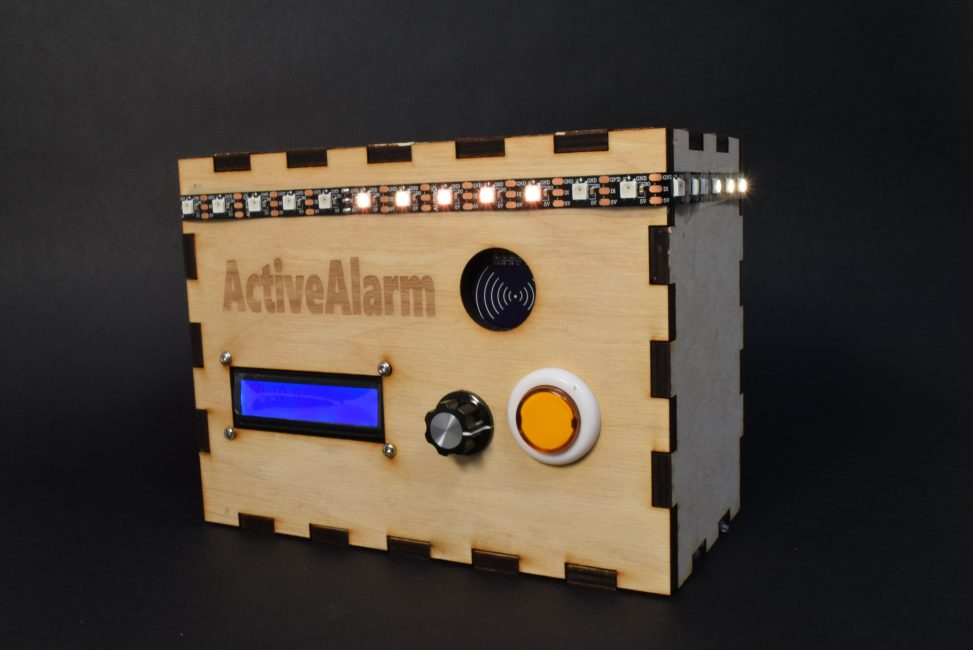
My project was an alarm clock that forces the user to get up and get active – the alarm will only stop ringing when the user goes to certain locations in their room in a specific, randomized order.
I noticed that I can only really wake up if I’m forced to get out of my bed and get moving. A lot of people also feel similarly, so it isn’t uncommon to place a phone alarm across the room to force one to get up and turn it off. But after that, it quite easy to slip back into bed and drift into sleep again. What if you had to go to multiple locations in your room, maybe in hard to reach nooks and crevices, in a specific order that is generated by the alarm? That way, you have to really get moving in order to truly turn it off. By that point, ideally, you won’t feel as strong of an urge to slip into bed.
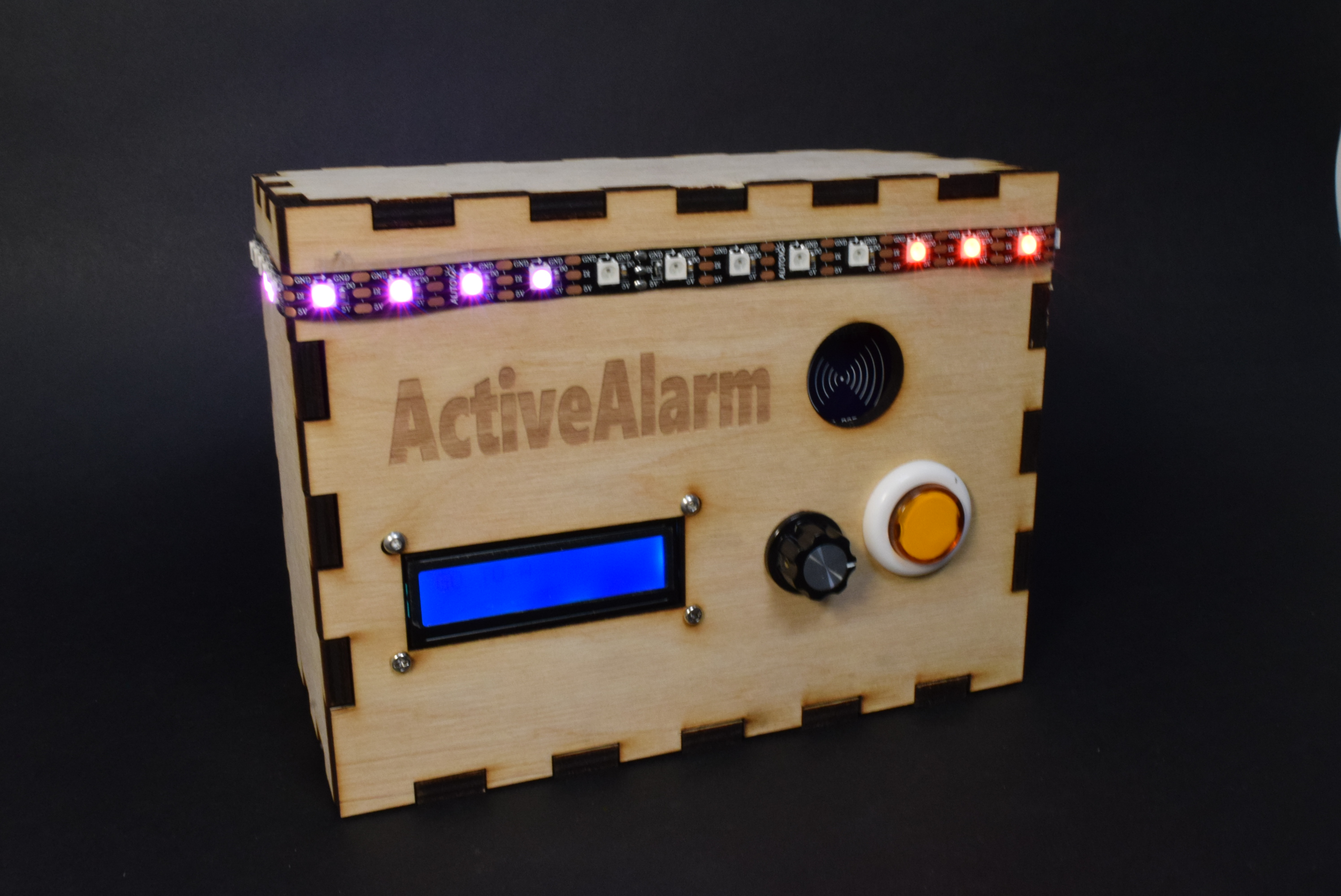
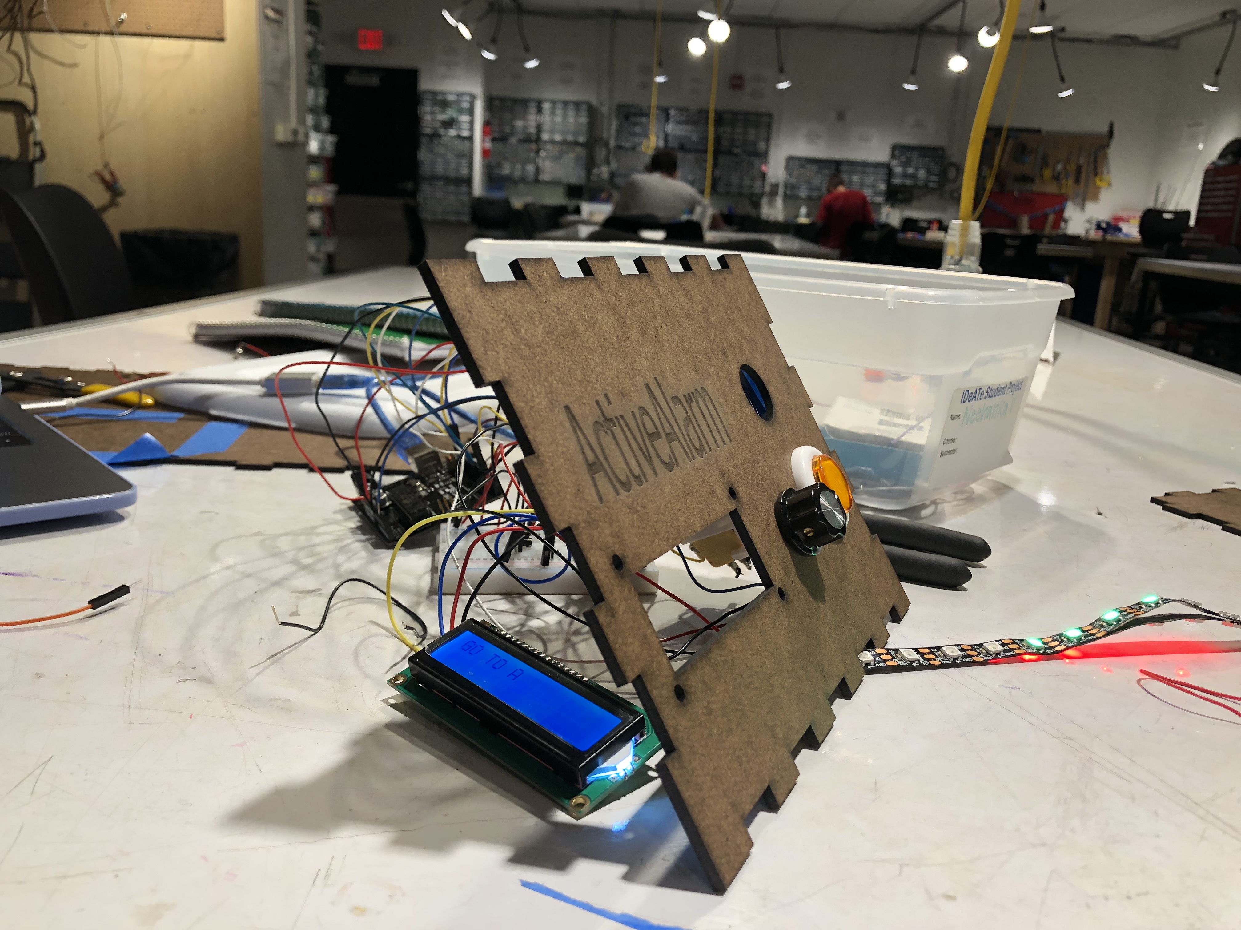
A front view of the alarm
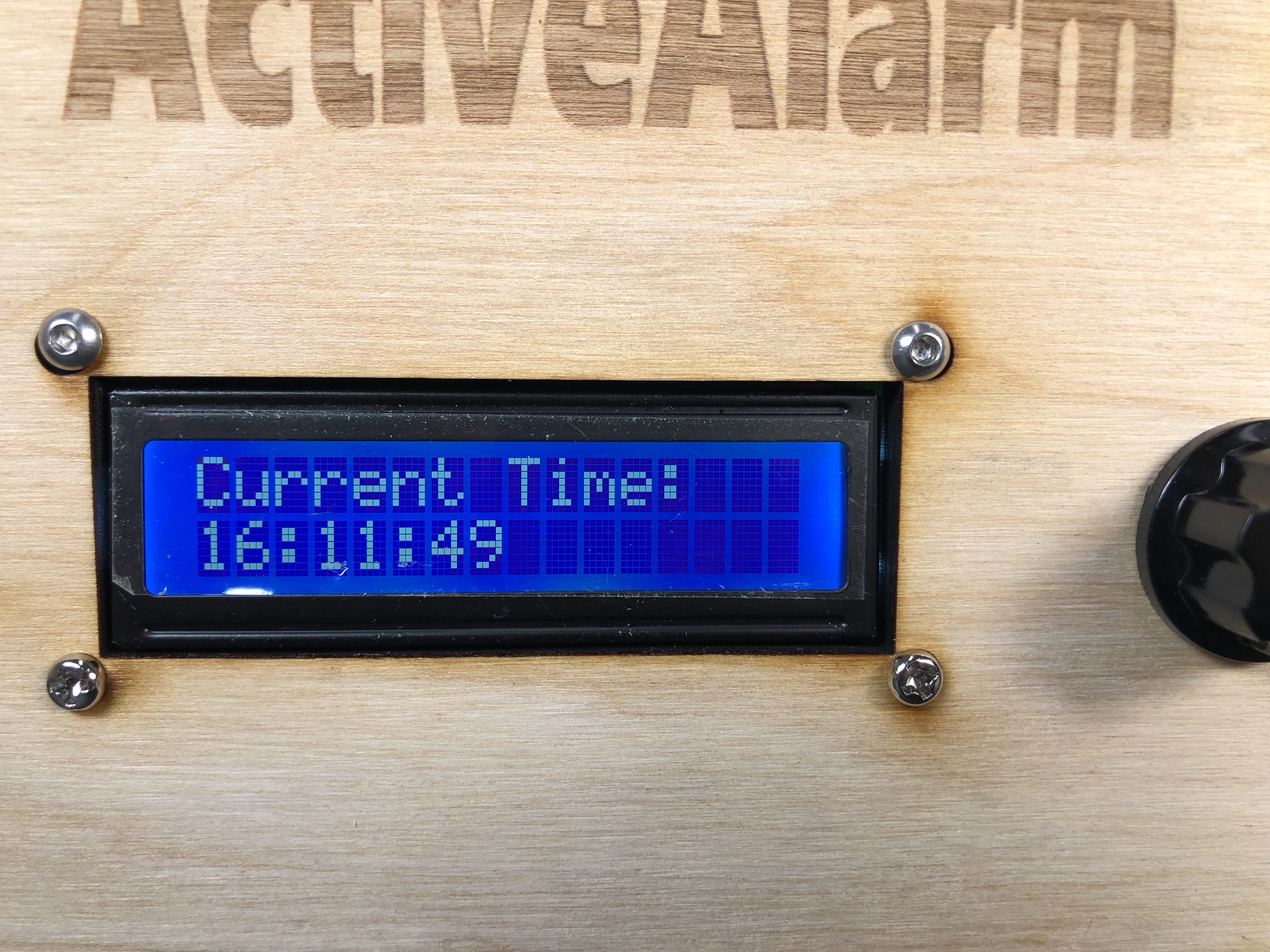
A close up of the LCD that will show the commands
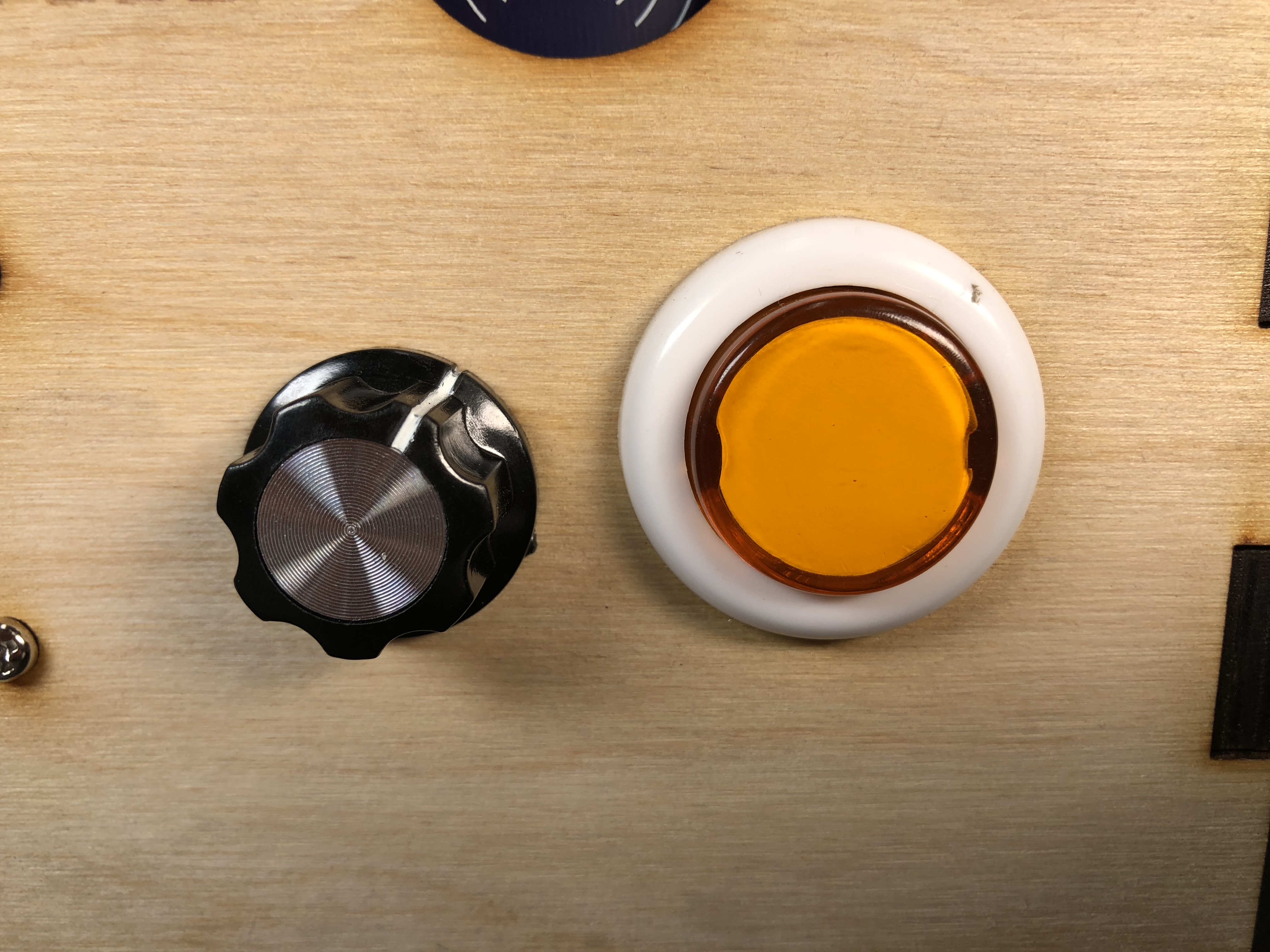
A close up of the button and dial the user will use to set the alarm
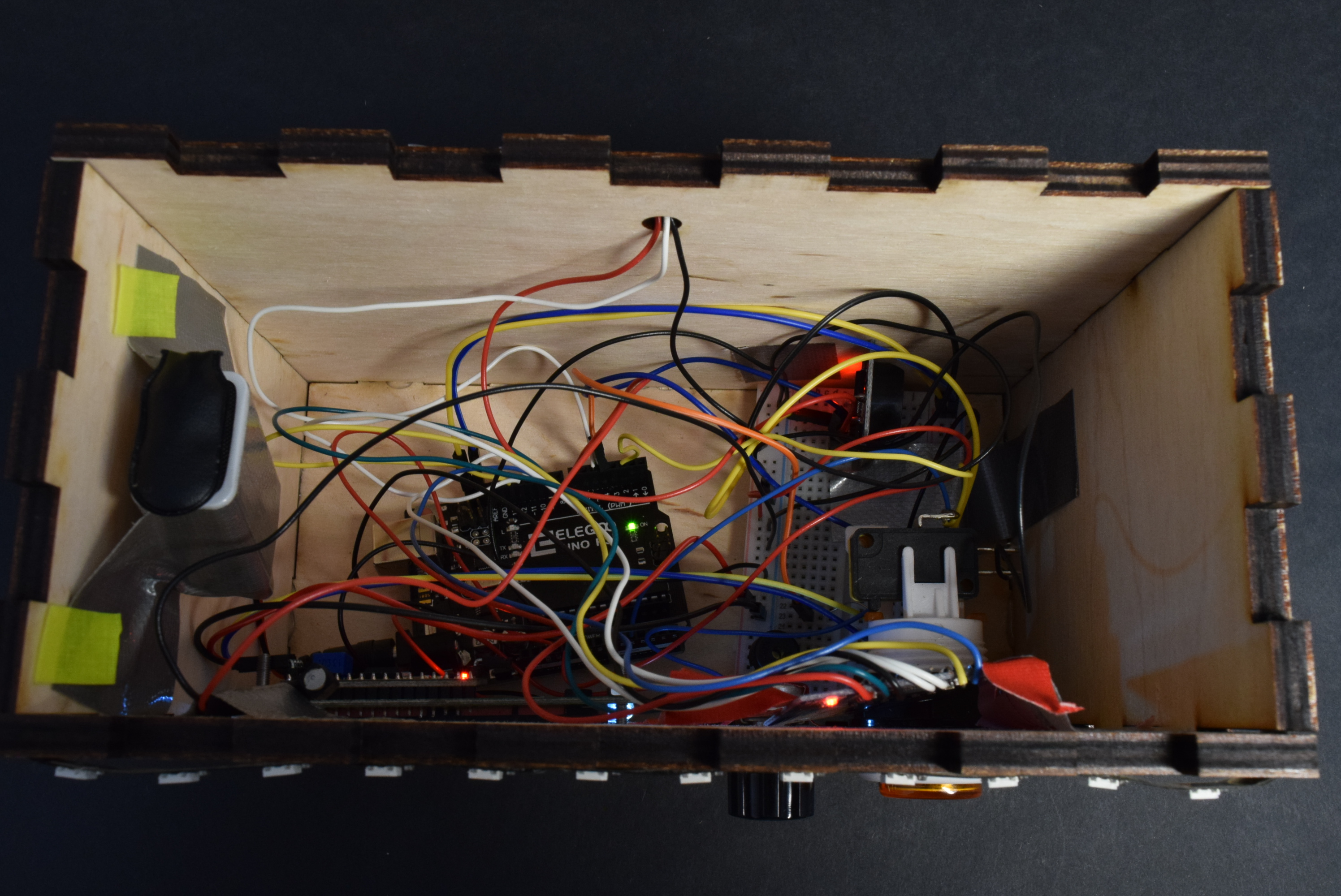
A look inside at all the electronics
Demo of setting the time I want the alarm to go off
A demo of how the alarm looks when it is set off and prompts the user to scan specific tags
Process
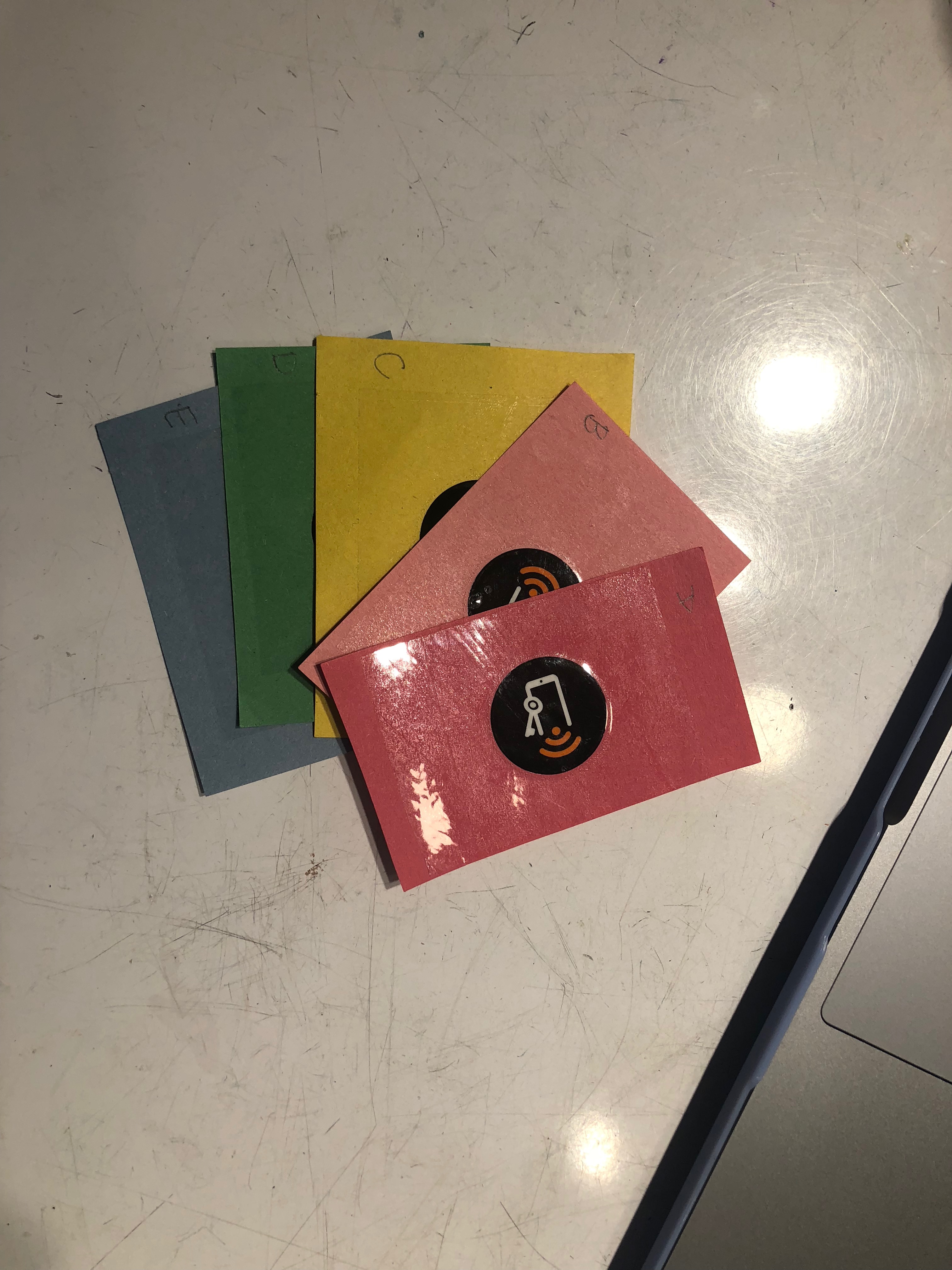
How I decided to represent locations in my room – simple tags on cards
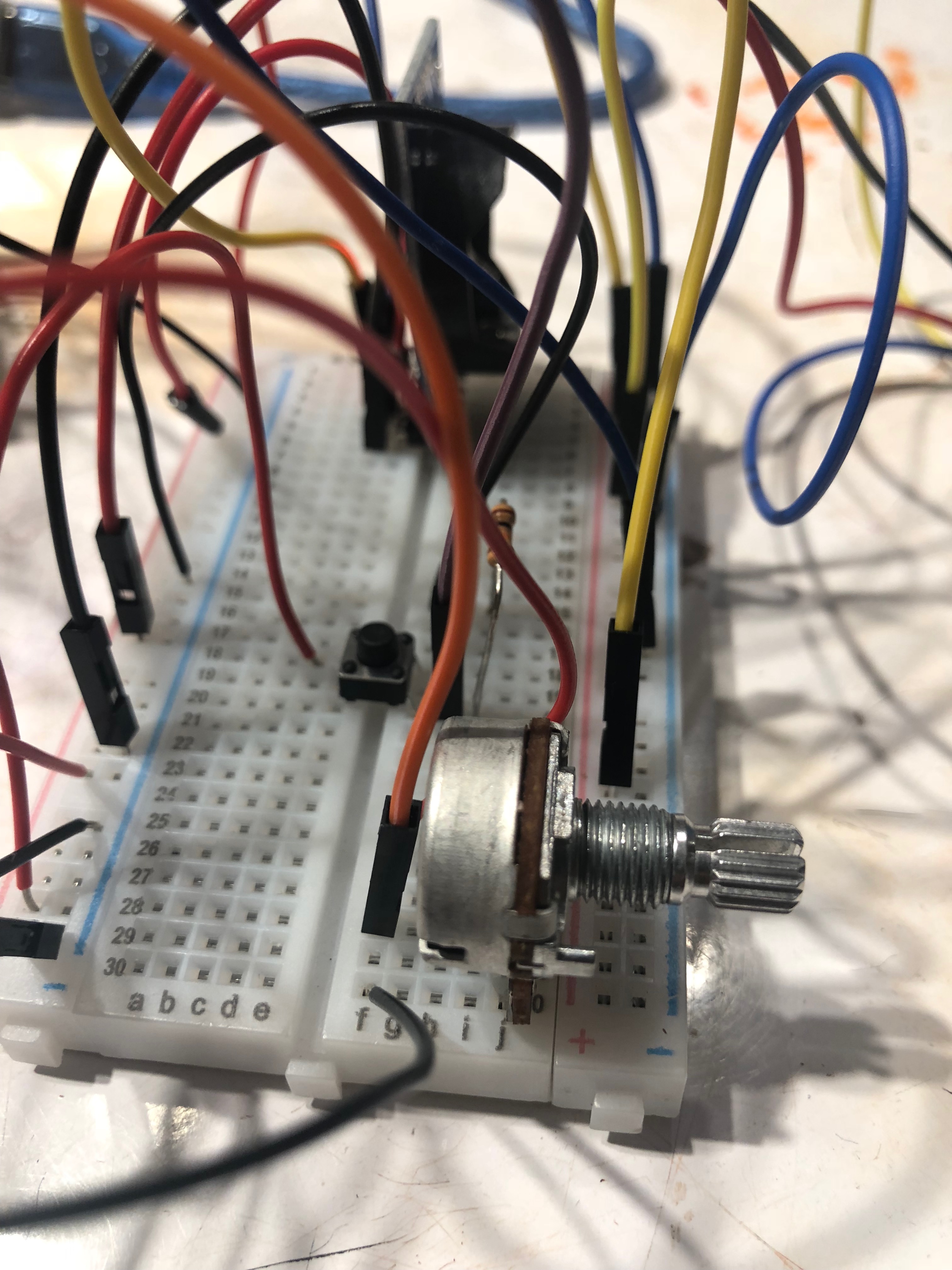
Getting a prototype “dial” and button to work
Getting the RFID scanner to work was the first hurdle I needed to pass. At first, I merely used female to male jumper cables to connect the scanner to the Arduino, which I expected to work perfectly. However, I was constantly getting error messages that no scanner was actually connected. Sometimes I got lucky and I would get a stray couple of bytes to show that something is hooked up before the same error messages would pop up again. I checked the wiring over and over again and replaced the scanner module multiple times. After a couple of hours, I was at my wit’s end and finally decided to solder the wires instead of just using jumper cables. After soldering, it worked perfectly. I still don’t know what the problem was, but if I didn’t decide to take the soldering approach, perhaps I would have opted to not use an RFID scanner at all. I’m really glad that it ended up working because the scanner ended up being a key part of this project’s appeal.
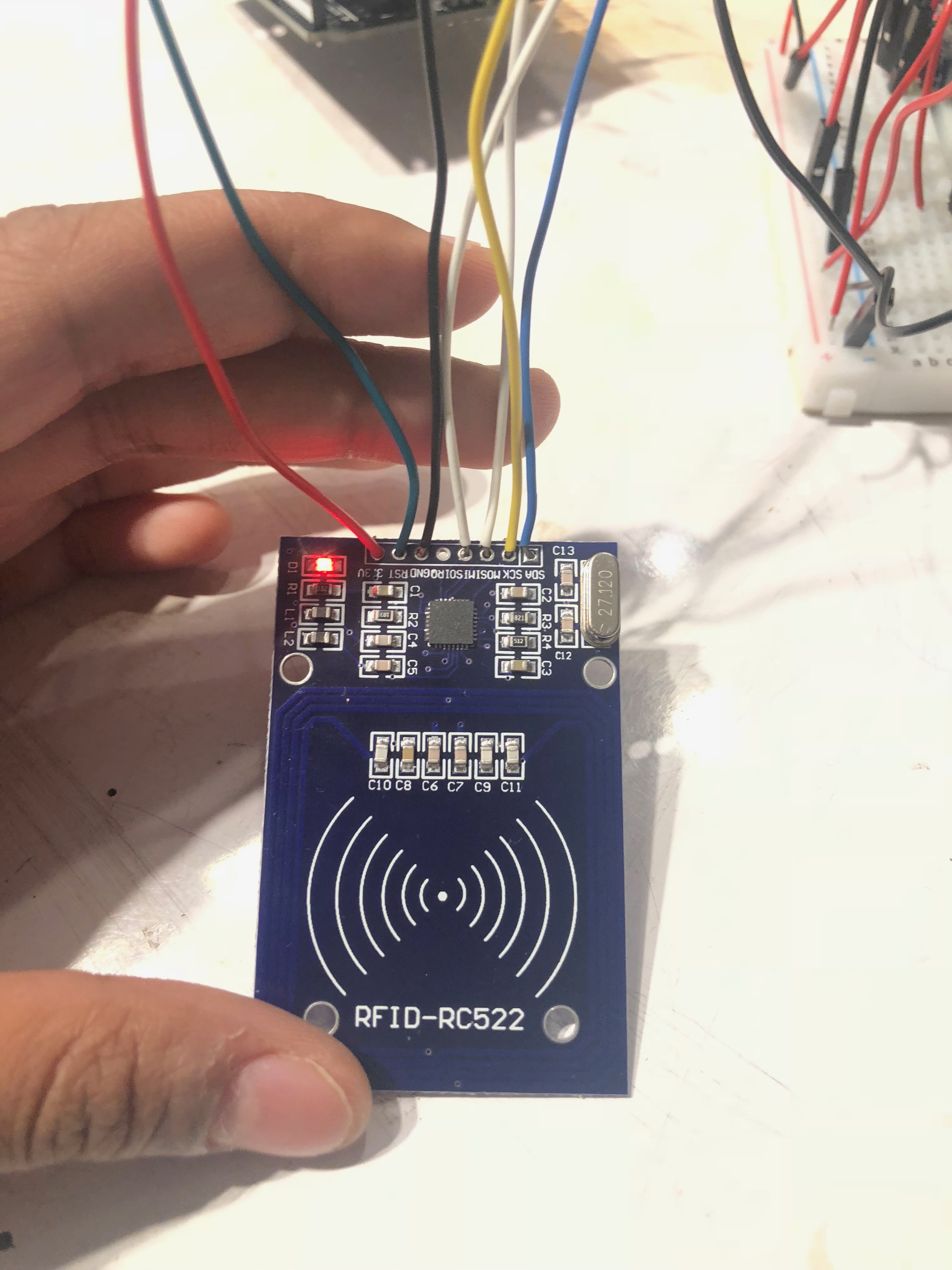
RFID lit up and working – This guy gave me a lot of trouble
Testing how I would mount the pieces onto the front, I ended up cutting out the wrong dimensions for the LCD, so I would have to redo this box
I didn’t wire my components with the understanding that I would later be putting in some kind of housing, I just wired it in the way that seemed the easiest and fastest at the moment. When it came to actually placing it in the box I cut out, I realized I would have to do a huge overhaul of the way I had everything organized, essentially tearing out all the wires and starting all over again. In future projects, I’ll keep in mind the final presentation while I design the hardware layout to save myself a lot of pain.
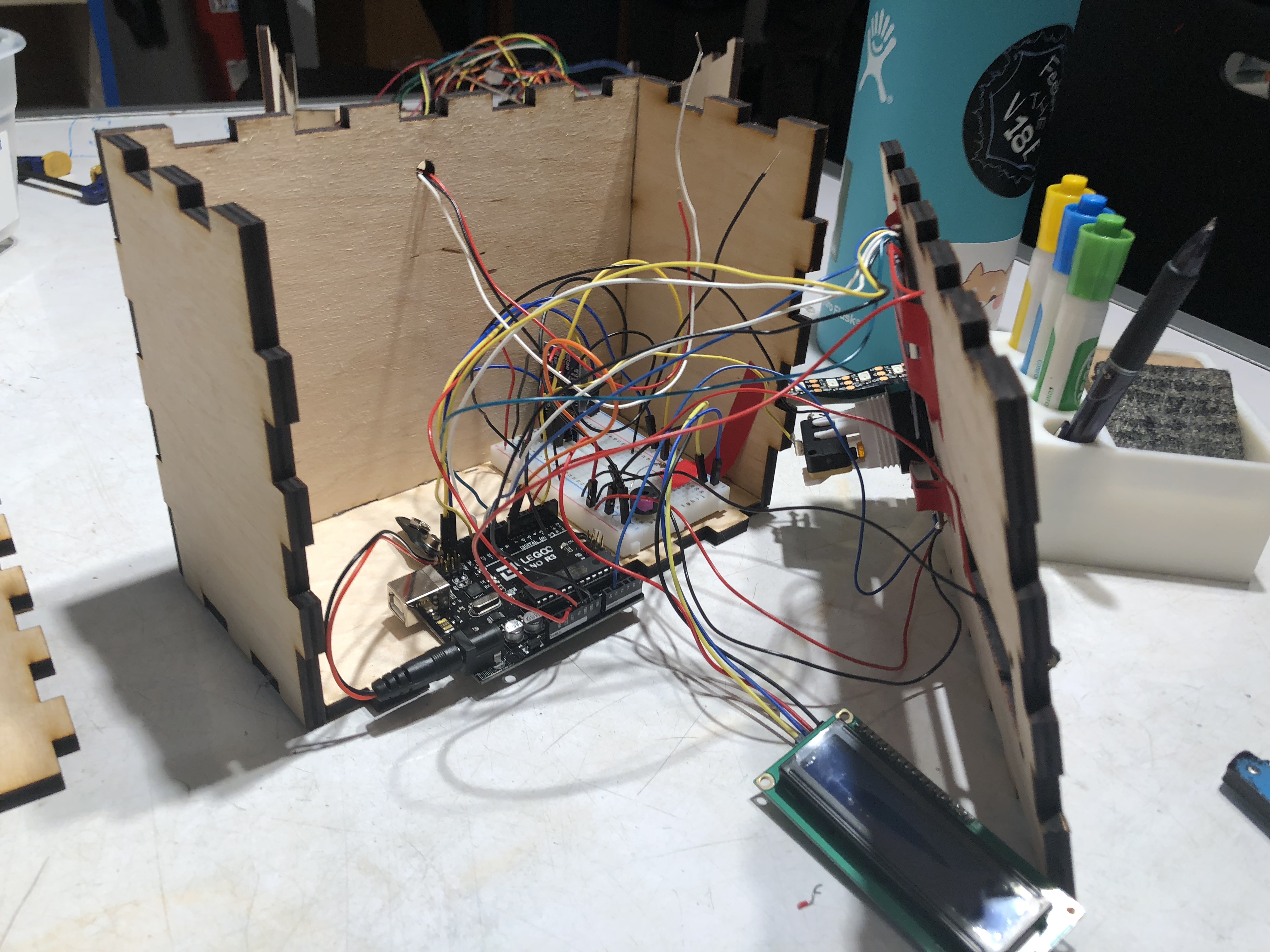
Getting everything into the box proved to be a big hassle, lots of wires came undone in the process. I pretty much had to rewire the entire project. Good learning experience.
Discussion
Response
“The LED strips look a little messy on the outside. Maybe put something on top of them to diffuse the light?“
I totally agree. Currently, my LED strip is held on by its own stickiness, extra double-sided tape, and prayers. I tried to make it look as straight as possible, but it definitely could be a lot straighter and neater. My original hope was that I could use an LED strip that was wrapped in white/clear silicone, so it would nicely diffuse the lights while maintaining brightness, but I didn’t know if we had this in the Physical Computing Lab. Of course, it is an alarm so we do want the lights to be a little jarring, so maybe diffusing may not necessarily be the way to go. However, I think maybe it could be in a sort of housing so that the LED strip isn’t just nakedly sitting on the box.
“If the tags are placed permanently in [a] different location, maybe you could put the RFID scanner on the opposite side of your interface so the buttons don’t interfere with you holding the box against the tags.“
I also agree with this critique. I realized as I was putting all the wires and components into the box that maybe it would be hard to scan the tags from the front, given there are buttons and knobs. I tried it out by sticking a tag on the wall and trying to scan it, and it did work after I tilted the box a little bit. This is definitely a design flaw that I should have kept in mind. This is not something I actively thought about while building because I simulated the walls by just bringing the tags to the RFID scanner location. Maybe it would have been better to put the RFID facing the back, which is flat and can be brought up to the wall.
Self-Critique
I’m pretty happy with how the project turned out. Visually, it looks very similar to my original drawings/concepts. However, I would probably not have a hole for the RFID sensor in a more refined project. I put it in this prototype because I thought that I would want to see the exact place of the sensor for debugging purposes, and I was unsure if it could scan through the wood. Now that I know it actually has quite a considerable range, I would not put a hole there and would merely etch a symbol to let the user know that this is the location to scan at. This would look a lot cleaner than the version I have now. I also think that some of my code is a little hacky, for lack of a better word, and that its efficiency can be improved considerably. If given more time, I would consider cleaning up my code so that maybe the project would run smoother.
What I Learned
There were points in the project that if I decided to fully pivot there, I would have gotten it to a functioning state much faster. An example is when I noticed that the RTC wasn’t showing the correct time, and in fact, would generate random times at bootup. For almost a week, this issue didn’t improve because the library I was using simply wasn’t capable of properly flashing the correct time to the RTC. It wasn’t until after I finally used another library did it fix itself. However, if I was just more willing to switch libraries earlier on, I could have fixed this and focused on other stuff. So advice to both past and future self: don’t be afraid to have to redo things to get something to function, sometimes you’re going to have to pivot from what you are currently using to a totally new tool, and you’re going to have to be okay with that.
Next Steps
My original vision for this project was that the RFID would just be one component of many. I’d also have to play with other sensors to turn off the alarm as well. For example, the alarm would need a photoresistor to read values above a certain threshold, either by bringing the alarm to the light or by binging my phone flashlight up to it. This would end up as almost like a “bop-it” alarm clock, as you have to complete certain commands in rapid succession to turn it off. I still think this is a fun idea and is probably the approach I would take if I decide to keep working on it. Also, currently, the only way to “cancel” an alarm a user has already set up is by ripping out the battery. I would definitely make a reset/off/cancel button in an improvement of this project.
I would also like to integrate this with a way to measure and display information sleep as well, perhaps with a mobile/web app. It would be great to record the number of hours slept, probably by adding another button to set when the user goes to sleep and then tracking until the alarm is turned off. I think displaying this information on a graph and running some analytics on it could be extremely useful to the user when deciding how to change their sleeping habits.
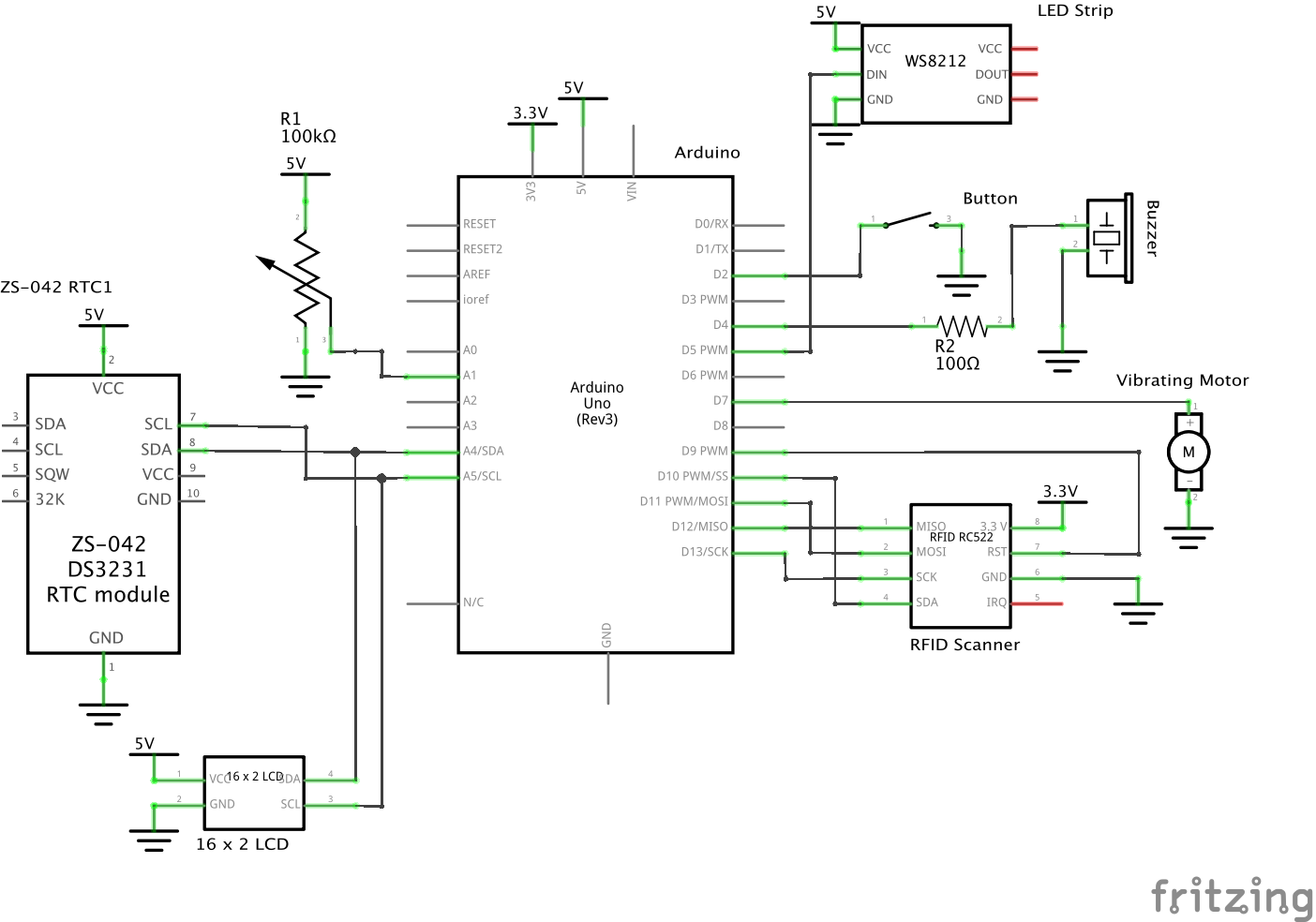
Schematic
Code
- <span class="com">/* Active Alarm
- * Neeharika Vogety (nvogety)
- *
- *
- * Summary: An alarm will ring, vibrate, and light up at a time that a user sets
- * to wake up at. The only way to turn off the alarm is to scan RFID tags set around
- * the room in a specific, randomly-generated order. The idea is to get the user up
- * and moving to turn off the alarm, rather than just hitting a button and going back to
- * sleep.
- *
- * Inputs:
- *
- * Arduino Pin | Input
- * 5 LED Strip Pin
- * 2 Button Pin
- * 9 RFID Pin
- * A1 Potentiometer Pin
- *
- * Outputs:
- *
- * Arduino pin | Output
- * 7 Vibrating Motor Pin
- * 4 Piezo Buzzer Pin
- */</span><span class="pln">
- </span><span class="com">#include</span><span class="pln"> </span><span class="str"><Wire.h></span><span class="pln">
- </span><span class="com">#include</span><span class="pln"> </span><span class="str"><Time.h></span><span class="pln">
- </span><span class="com">#include</span><span class="pln"> </span><span class="str"><LiquidCrystal_I2C.h></span><span class="pln">
- </span><span class="com">#include</span><span class="pln"> </span><span class="str"><RTClib.h></span><span class="pln">
- </span><span class="com">#include</span><span class="pln"> </span><span class="str"><SPI.h></span><span class="pln">
- </span><span class="com">#include</span><span class="pln"> </span><span class="str"><MFRC522.h></span><span class="pln">
- </span><span class="com">#include</span><span class="pln"> </span><span class="str"><FastLED.h></span><span class="pln">
- </span><span class="com">// Define important pins for RFID</span><span class="pln">
- </span><span class="com">#define</span><span class="pln"> RST_PIN </span><span class="lit">9</span><span class="pln">
- </span><span class="com">#define</span><span class="pln"> SS_PIN </span><span class="lit">10</span><span class="pln">
- </span><span class="com">#define</span><span class="pln"> TASKSLEN </span><span class="lit">5</span><span class="pln"> </span><span class="com">// Define length of tasks array, used throughout code</span><span class="pln">
- </span><span class="com">// Define important constants for LED strip</span><span class="pln">
- </span><span class="com">#define</span><span class="pln"> LED_PIN </span><span class="lit">5</span><span class="pln">
- </span><span class="com">#define</span><span class="pln"> NUM_LEDS </span><span class="lit">45</span><span class="pln">
- </span><span class="com">#define</span><span class="pln"> BRIGHTNESS </span><span class="lit">200</span><span class="pln">
- </span><span class="com">#define</span><span class="pln"> LED_TYPE WS2811
- </span><span class="com">#define</span><span class="pln"> COLOR_ORDER GRB
- CRGB leds</span><span class="pun">[</span><span class="pln">NUM_LEDS</span><span class="pun">];</span><span class="pln">
- </span><span class="com">#define</span><span class="pln"> UPDATES_PER_SECOND </span><span class="lit">100</span><span class="pln">
- </span><span class="typ">CRGBPalette16</span><span class="pln"> currentPalette</span><span class="pun">;</span><span class="pln">
- </span><span class="typ">TBlendType</span><span class="pln"> currentBlending</span><span class="pun">;</span><span class="pln">
- </span><span class="kwd">typedef</span><span class="pln"> </span><span class="kwd">struct</span><span class="pun">{</span><span class="pln">
- </span><span class="kwd">char</span><span class="pln"> </span><span class="pun">*</span><span class="pln">tagName</span><span class="pun">;</span><span class="pln">
- </span><span class="kwd">char</span><span class="pln"> </span><span class="pun">*</span><span class="pln">tagUID</span><span class="pun">;</span><span class="pln">
- </span><span class="pun">}</span><span class="pln"> </span><span class="typ">Tag</span><span class="pun">;</span><span class="pln">
- </span><span class="com">// An array of Tag structs that links together</span><span class="pln">
- </span><span class="com">// the name of the tag and the ID of the tag.</span><span class="pln">
- </span><span class="com">// If this is changed, must change TASKLEN at</span><span class="pln">
- </span><span class="com">// the top!</span><span class="pln">
- </span><span class="typ">Tag</span><span class="pln"> tasks</span><span class="pun">[</span><span class="pln">TASKSLEN</span><span class="pun">]</span><span class="pln"> </span><span class="pun">=</span><span class="pln"> </span><span class="pun">{</span><span class="pln">
- </span><span class="pun">{</span><span class="str">"A"</span><span class="pun">,</span><span class="pln"> </span><span class="str">"437B172845C81"</span><span class="pun">},</span><span class="pln">
- </span><span class="pun">{</span><span class="str">"B"</span><span class="pun">,</span><span class="pln"> </span><span class="str">"450B072845C80"</span><span class="pun">},</span><span class="pln">
- </span><span class="pun">{</span><span class="str">"C"</span><span class="pun">,</span><span class="pln"> </span><span class="str">"42FB172845C81"</span><span class="pun">},</span><span class="pln">
- </span><span class="pun">{</span><span class="str">"D"</span><span class="pun">,</span><span class="pln"> </span><span class="str">"461DF72845C80"</span><span class="pun">},</span><span class="pln">
- </span><span class="pun">{</span><span class="str">"E"</span><span class="pun">,</span><span class="pln"> </span><span class="str">"49ED972845C80"</span><span class="pun">},</span><span class="pln">
- </span><span class="pun">};</span><span class="pln">
- </span><span class="kwd">int</span><span class="pln"> nums</span><span class="pun">[</span><span class="pln">TASKSLEN</span><span class="pun">];</span><span class="pln"> </span><span class="com">// Create nums array</span><span class="pln">
- </span><span class="kwd">int</span><span class="pln"> numOrder</span><span class="pun">[</span><span class="pln">TASKSLEN</span><span class="pun">];</span><span class="pln"> </span><span class="com">// Create num Order array</span><span class="pln">
- </span><span class="kwd">int</span><span class="pln"> nOindex </span><span class="pun">=</span><span class="pln"> </span><span class="lit">0</span><span class="pun">;</span><span class="pln"> </span><span class="com">// Index to traverse num Order</span><span class="pln">
- </span><span class="com">// Bools that we will use to execute certain parts of the code</span><span class="pln">
- </span><span class="kwd">bool</span><span class="pln"> startGeneration </span><span class="pun">=</span><span class="pln"> </span><span class="kwd">false</span><span class="pun">;</span><span class="pln">
- </span><span class="kwd">bool</span><span class="pln"> readRFID </span><span class="pun">=</span><span class="pln"> </span><span class="kwd">false</span><span class="pun">;</span><span class="pln">
- </span><span class="kwd">bool</span><span class="pln"> setAlarm </span><span class="pun">=</span><span class="pln"> </span><span class="kwd">true</span><span class="pun">;</span><span class="pln">
- </span><span class="kwd">bool</span><span class="pln"> alarmSet </span><span class="pun">=</span><span class="pln"> </span><span class="kwd">false</span><span class="pun">;</span><span class="pln">
- </span><span class="com">// Hour and Minute, will set with RTC</span><span class="pln">
- </span><span class="kwd">int</span><span class="pln"> alarmHour</span><span class="pun">;</span><span class="pln">
- </span><span class="kwd">int</span><span class="pln"> alarmMin</span><span class="pun">;</span><span class="pln">
- </span><span class="typ">LiquidCrystal_I2C</span><span class="pln"> screen</span><span class="pun">(</span><span class="lit">0x27</span><span class="pun">,</span><span class="pln"> </span><span class="lit">16</span><span class="pun">,</span><span class="pln"> </span><span class="lit">2</span><span class="pun">);</span><span class="pln"> </span><span class="com">//Create Screen object</span><span class="pln">
- MFRC522 mfrc522</span><span class="pun">(</span><span class="pln">SS_PIN</span><span class="pun">,</span><span class="pln"> RST_PIN</span><span class="pun">);</span><span class="pln"> </span><span class="com">// Create MFRC522 instance</span><span class="pln">
- DS1307 RTC</span><span class="pun">;</span><span class="pln"> </span><span class="com">// Create RTC object</span><span class="pln">
- </span><span class="com">// Initialize constant i/o pins</span><span class="pln">
- </span><span class="kwd">const</span><span class="pln"> </span><span class="kwd">int</span><span class="pln"> BUTTONPIN </span><span class="pun">=</span><span class="pln"> </span><span class="lit">2</span><span class="pun">;</span><span class="pln">
- </span><span class="kwd">const</span><span class="pln"> </span><span class="kwd">int</span><span class="pln"> POTPIN </span><span class="pun">=</span><span class="pln"> A1</span><span class="pun">;</span><span class="pln">
- </span><span class="kwd">const</span><span class="pln"> </span><span class="kwd">int</span><span class="pln"> VIBRPIN </span><span class="pun">=</span><span class="pln"> </span><span class="lit">7</span><span class="pun">;</span><span class="pln">
- </span><span class="kwd">const</span><span class="pln"> </span><span class="kwd">int</span><span class="pln"> BUZZERPIN </span><span class="pun">=</span><span class="pln"> </span><span class="lit">4</span><span class="pun">;</span><span class="pln">
- </span><span class="kwd">void</span><span class="pln"> setup</span><span class="pun">()</span><span class="pln"> </span><span class="pun">{</span><span class="pln">
- </span><span class="typ">Serial</span><span class="pun">.</span><span class="kwd">begin</span><span class="pun">(</span><span class="lit">9600</span><span class="pun">);</span><span class="pln">
- </span><span class="com">// Set up INPUTS AND OUTPUTS</span><span class="pln">
- pinMode</span><span class="pun">(</span><span class="pln">BUTTONPIN</span><span class="pun">,</span><span class="pln"> INPUT_PULLUP</span><span class="pun">);</span><span class="pln">
- pinMode</span><span class="pun">(</span><span class="pln">POTPIN</span><span class="pun">,</span><span class="pln"> INPUT</span><span class="pun">);</span><span class="pln">
- pinMode</span><span class="pun">(</span><span class="pln">VIBRPIN</span><span class="pun">,</span><span class="pln"> OUTPUT</span><span class="pun">);</span><span class="pln">
- pinMode</span><span class="pun">(</span><span class="pln">BUZZERPIN</span><span class="pun">,</span><span class="pln"> OUTPUT</span><span class="pun">);</span><span class="pln">
- </span><span class="com">// Set up RFID</span><span class="pln">
- SPI</span><span class="pun">.</span><span class="kwd">begin</span><span class="pun">();</span><span class="pln"> </span><span class="com">// Init SPI bus</span><span class="pln">
- mfrc522</span><span class="pun">.</span><span class="pln">PCD_Init</span><span class="pun">();</span><span class="pln"> </span><span class="com">// Init MFRC522</span><span class="pln">
- delay</span><span class="pun">(</span><span class="lit">4</span><span class="pun">);</span><span class="pln">
- mfrc522</span><span class="pun">.</span><span class="pln">PCD_DumpVersionToSerial</span><span class="pun">();</span><span class="pln"> </span><span class="com">// Make sure RFID is up and running</span><span class="pln">
- </span><span class="com">// Start RTC</span><span class="pln">
- RTC</span><span class="pun">.</span><span class="kwd">begin</span><span class="pun">();</span><span class="pln">
- </span><span class="com">//Set up LED String</span><span class="pln">
- </span><span class="typ">FastLED</span><span class="pun">.</span><span class="pln">addLeds</span><span class="pun"><</span><span class="pln">LED_TYPE</span><span class="pun">,</span><span class="pln"> LED_PIN</span><span class="pun">,</span><span class="pln"> COLOR_ORDER</span><span class="pun">>(</span><span class="pln">leds</span><span class="pun">,</span><span class="pln"> NUM_LEDS</span><span class="pun">).</span><span class="pln">setCorrection</span><span class="pun">(</span><span class="pln"> </span><span class="typ">TypicalLEDStrip</span><span class="pln"> </span><span class="pun">);</span><span class="pln">
- </span><span class="typ">FastLED</span><span class="pun">.</span><span class="pln">setBrightness</span><span class="pun">(</span><span class="pln"> BRIGHTNESS </span><span class="pun">);</span><span class="pln">
- currentPalette </span><span class="pun">=</span><span class="pln"> </span><span class="typ">RainbowStripeColors_p</span><span class="pun">;</span><span class="pln">
- currentBlending </span><span class="pun">=</span><span class="pln"> NOBLEND</span><span class="pun">;</span><span class="pln">
- clearLEDs</span><span class="pun">();</span><span class="pln">
- </span><span class="com">// Clear LCD screen and signal set up is over</span><span class="pln">
- screen</span><span class="pun">.</span><span class="pln">init</span><span class="pun">();</span><span class="pln">
- screen</span><span class="pun">.</span><span class="pln">backlight</span><span class="pun">();</span><span class="pln">
- screen</span><span class="pun">.</span><span class="pln">home</span><span class="pun">();</span><span class="pln">
- screen</span><span class="pun">.</span><span class="kwd">print</span><span class="pun">(</span><span class="str">"Booting up.."</span><span class="pun">);</span><span class="pln">
- delay</span><span class="pun">(</span><span class="lit">1000</span><span class="pun">);</span><span class="pln">
- screen</span><span class="pun">.</span><span class="pln">clear</span><span class="pun">();</span><span class="pln">
- </span><span class="pun">}</span><span class="pln">
- </span><span class="kwd">void</span><span class="pln"> loop</span><span class="pun">()</span><span class="pln"> </span><span class="pun">{</span><span class="pln">
- </span><span class="com">// If we still need to set an alarm time,</span><span class="pln">
- </span><span class="com">// display the current time and wait for button press</span><span class="pln">
- </span><span class="com">// to set the hour, then the minute of the alarm, and</span><span class="pln">
- </span><span class="com">// set the alarm</span><span class="pln">
- </span><span class="kwd">if</span><span class="pun">(</span><span class="pln">setAlarm</span><span class="pun">){</span><span class="pln">
- </span><span class="com">// Display time until button is pressed</span><span class="pln">
- </span><span class="kwd">while</span><span class="pun">(</span><span class="pln">digitalRead</span><span class="pun">(</span><span class="pln">BUTTONPIN</span><span class="pun">)</span><span class="pln"> </span><span class="pun">==</span><span class="pln"> LOW</span><span class="pun">){</span><span class="pln">
- </span><span class="typ">DateTime</span><span class="pln"> now </span><span class="pun">=</span><span class="pln"> RTC</span><span class="pun">.</span><span class="pln">now</span><span class="pun">();</span><span class="pln">
- screen</span><span class="pun">.</span><span class="pln">clear</span><span class="pun">();</span><span class="pln">
- screen</span><span class="pun">.</span><span class="pln">setCursor</span><span class="pun">(</span><span class="lit">0</span><span class="pun">,</span><span class="pln"> </span><span class="lit">0</span><span class="pun">);</span><span class="pln">
- screen</span><span class="pun">.</span><span class="kwd">print</span><span class="pun">(</span><span class="str">"Current Time:"</span><span class="pun">);</span><span class="pln">
- screen</span><span class="pun">.</span><span class="pln">setCursor</span><span class="pun">(</span><span class="lit">0</span><span class="pun">,</span><span class="pln"> </span><span class="lit">1</span><span class="pun">);</span><span class="pln">
- </span><span class="kwd">if</span><span class="pun">(</span><span class="pln">now</span><span class="pun">.</span><span class="pln">hour</span><span class="pun">()</span><span class="pln"> </span><span class="pun"><=</span><span class="pln"> </span><span class="lit">9</span><span class="pun">){</span><span class="pln">
- screen</span><span class="pun">.</span><span class="kwd">print</span><span class="pun">(</span><span class="str">"0"</span><span class="pun">);</span><span class="pln">
- </span><span class="pun">}</span><span class="pln">
- screen</span><span class="pun">.</span><span class="kwd">print</span><span class="pun">(</span><span class="pln">now</span><span class="pun">.</span><span class="pln">hour</span><span class="pun">());</span><span class="pln">
- screen</span><span class="pun">.</span><span class="kwd">print</span><span class="pun">(</span><span class="str">":"</span><span class="pun">);</span><span class="pln">
- </span><span class="kwd">if</span><span class="pun">(</span><span class="pln">now</span><span class="pun">.</span><span class="pln">minute</span><span class="pun">()</span><span class="pln"> </span><span class="pun"><=</span><span class="pln"> </span><span class="lit">9</span><span class="pun">){</span><span class="pln">
- screen</span><span class="pun">.</span><span class="kwd">print</span><span class="pun">(</span><span class="str">"0"</span><span class="pun">);</span><span class="pln">
- </span><span class="pun">}</span><span class="pln">
- screen</span><span class="pun">.</span><span class="kwd">print</span><span class="pun">(</span><span class="pln">now</span><span class="pun">.</span><span class="pln">minute</span><span class="pun">());</span><span class="pln">
- screen</span><span class="pun">.</span><span class="kwd">print</span><span class="pun">(</span><span class="str">":"</span><span class="pun">);</span><span class="pln">
- </span><span class="kwd">if</span><span class="pun">(</span><span class="pln">now</span><span class="pun">.</span><span class="pln">second</span><span class="pun">()</span><span class="pln"> </span><span class="pun"><=</span><span class="pln"> </span><span class="lit">9</span><span class="pun">){</span><span class="pln">
- screen</span><span class="pun">.</span><span class="kwd">print</span><span class="pun">(</span><span class="str">"0"</span><span class="pun">);</span><span class="pln">
- </span><span class="pun">}</span><span class="pln">
- screen</span><span class="pun">.</span><span class="kwd">print</span><span class="pun">(</span><span class="pln">now</span><span class="pun">.</span><span class="pln">second</span><span class="pun">());</span><span class="pln">
- delay</span><span class="pun">(</span><span class="lit">1000</span><span class="pun">);</span><span class="pln">
- </span><span class="pun">}</span><span class="pln">
- delay</span><span class="pun">(</span><span class="lit">1000</span><span class="pun">);</span><span class="pln">
- </span><span class="com">// Allow user to set up hour of alarm until button is pressed again</span><span class="pln">
- </span><span class="kwd">while</span><span class="pun">(</span><span class="pln">digitalRead</span><span class="pun">(</span><span class="pln">BUTTONPIN</span><span class="pun">)</span><span class="pln"> </span><span class="pun">==</span><span class="pln"> LOW</span><span class="pun">){</span><span class="pln">
- screen</span><span class="pun">.</span><span class="pln">clear</span><span class="pun">();</span><span class="pln">
- screen</span><span class="pun">.</span><span class="pln">setCursor</span><span class="pun">(</span><span class="lit">0</span><span class="pun">,</span><span class="pln"> </span><span class="lit">0</span><span class="pun">);</span><span class="pln">
- screen</span><span class="pun">.</span><span class="kwd">print</span><span class="pun">(</span><span class="str">"Set Alarm Hour:"</span><span class="pun">);</span><span class="pln">
- </span><span class="com">// Set alarm hour with potentiometer</span><span class="pln">
- alarmHour </span><span class="pun">=</span><span class="pln"> map</span><span class="pun">(</span><span class="pln">analogRead</span><span class="pun">(</span><span class="pln">POTPIN</span><span class="pun">),</span><span class="pln"> </span><span class="lit">0</span><span class="pun">,</span><span class="pln"> </span><span class="lit">1023</span><span class="pun">,</span><span class="pln"> </span><span class="lit">0</span><span class="pun">,</span><span class="pln"> </span><span class="lit">24</span><span class="pun">);</span><span class="pln">
- screen</span><span class="pun">.</span><span class="pln">setCursor</span><span class="pun">(</span><span class="lit">0</span><span class="pun">,</span><span class="pln"> </span><span class="lit">1</span><span class="pun">);</span><span class="pln">
- </span><span class="kwd">if</span><span class="pun">(</span><span class="pln">alarmHour </span><span class="pun"><=</span><span class="pln"> </span><span class="lit">9</span><span class="pun">){</span><span class="pln">
- screen</span><span class="pun">.</span><span class="kwd">print</span><span class="pun">(</span><span class="str">"0"</span><span class="pun">);</span><span class="pln">
- </span><span class="pun">}</span><span class="pln">
- screen</span><span class="pun">.</span><span class="kwd">print</span><span class="pun">(</span><span class="pln">alarmHour</span><span class="pun">);</span><span class="pln">
- delay</span><span class="pun">(</span><span class="lit">250</span><span class="pun">);</span><span class="pln">
- </span><span class="pun">}</span><span class="pln">
- delay</span><span class="pun">(</span><span class="lit">1000</span><span class="pun">);</span><span class="pln">
- </span><span class="com">// Allow user to set up minute of alarm until button is pressed again</span><span class="pln">
- </span><span class="kwd">while</span><span class="pun">(</span><span class="pln">digitalRead</span><span class="pun">(</span><span class="pln">BUTTONPIN</span><span class="pun">)</span><span class="pln"> </span><span class="pun">==</span><span class="pln"> LOW</span><span class="pun">){</span><span class="pln">
- screen</span><span class="pun">.</span><span class="pln">clear</span><span class="pun">();</span><span class="pln">
- screen</span><span class="pun">.</span><span class="pln">setCursor</span><span class="pun">(</span><span class="lit">0</span><span class="pun">,</span><span class="pln"> </span><span class="lit">0</span><span class="pun">);</span><span class="pln">
- screen</span><span class="pun">.</span><span class="kwd">print</span><span class="pun">(</span><span class="str">"Set Alarm Minute:"</span><span class="pun">);</span><span class="pln">
- </span><span class="com">// Set alarm minute with potentiometer</span><span class="pln">
- alarmMin </span><span class="pun">=</span><span class="pln"> map</span><span class="pun">(</span><span class="pln">analogRead</span><span class="pun">(</span><span class="pln">POTPIN</span><span class="pun">),</span><span class="pln"> </span><span class="lit">0</span><span class="pun">,</span><span class="pln"> </span><span class="lit">1023</span><span class="pun">,</span><span class="pln"> </span><span class="lit">0</span><span class="pun">,</span><span class="pln"> </span><span class="lit">60</span><span class="pun">);</span><span class="pln">
- screen</span><span class="pun">.</span><span class="pln">setCursor</span><span class="pun">(</span><span class="lit">0</span><span class="pun">,</span><span class="pln"> </span><span class="lit">1</span><span class="pun">);</span><span class="pln">
- </span><span class="kwd">if</span><span class="pun">(</span><span class="pln">alarmMin </span><span class="pun"><=</span><span class="pln"> </span><span class="lit">9</span><span class="pun">){</span><span class="pln">
- screen</span><span class="pun">.</span><span class="kwd">print</span><span class="pun">(</span><span class="str">"0"</span><span class="pun">);</span><span class="pln">
- </span><span class="pun">}</span><span class="pln">
- screen</span><span class="pun">.</span><span class="kwd">print</span><span class="pun">(</span><span class="pln">alarmMin</span><span class="pun">);</span><span class="pln">
- delay</span><span class="pun">(</span><span class="lit">250</span><span class="pun">);</span><span class="pln">
- </span><span class="pun">}</span><span class="pln">
- delay</span><span class="pun">(</span><span class="lit">1000</span><span class="pun">);</span><span class="pln">
- </span><span class="com">// Show when alarm is set for</span><span class="pln">
- screen</span><span class="pun">.</span><span class="pln">clear</span><span class="pun">();</span><span class="pln">
- screen</span><span class="pun">.</span><span class="pln">setCursor</span><span class="pun">(</span><span class="lit">0</span><span class="pun">,</span><span class="pln"> </span><span class="lit">0</span><span class="pun">);</span><span class="pln">
- screen</span><span class="pun">.</span><span class="kwd">print</span><span class="pun">(</span><span class="str">"Alarm set for:"</span><span class="pun">);</span><span class="pln">
- screen</span><span class="pun">.</span><span class="pln">setCursor</span><span class="pun">(</span><span class="lit">0</span><span class="pun">,</span><span class="pln"> </span><span class="lit">1</span><span class="pun">);</span><span class="pln">
- </span><span class="kwd">if</span><span class="pun">(</span><span class="pln">alarmHour </span><span class="pun"><=</span><span class="pln"> </span><span class="lit">9</span><span class="pun">){</span><span class="pln">
- screen</span><span class="pun">.</span><span class="kwd">print</span><span class="pun">(</span><span class="str">"0"</span><span class="pun">);</span><span class="pln">
- </span><span class="pun">}</span><span class="pln">
- screen</span><span class="pun">.</span><span class="kwd">print</span><span class="pun">(</span><span class="pln">alarmHour</span><span class="pun">);</span><span class="pln">
- screen</span><span class="pun">.</span><span class="kwd">print</span><span class="pun">(</span><span class="str">":"</span><span class="pun">);</span><span class="pln">
- </span><span class="kwd">if</span><span class="pun">(</span><span class="pln">alarmMin </span><span class="pun"><=</span><span class="pln"> </span><span class="lit">9</span><span class="pun">){</span><span class="pln">
- screen</span><span class="pun">.</span><span class="kwd">print</span><span class="pun">(</span><span class="str">"0"</span><span class="pun">);</span><span class="pln">
- </span><span class="pun">}</span><span class="pln">
- screen</span><span class="pun">.</span><span class="kwd">print</span><span class="pun">(</span><span class="pln">alarmMin</span><span class="pun">);</span><span class="pln">
- setAlarm </span><span class="pun">=</span><span class="pln"> </span><span class="kwd">false</span><span class="pun">;</span><span class="pln">
- alarmSet </span><span class="pun">=</span><span class="pln"> </span><span class="kwd">true</span><span class="pun">;</span><span class="pln">
- </span><span class="pun">}</span><span class="pln">
- </span><span class="com">// Keep checking if current hour and minute is what we set for the alarm</span><span class="pln">
- </span><span class="kwd">if</span><span class="pun">(</span><span class="pln">alarmSet</span><span class="pun">){</span><span class="pln">
- </span><span class="typ">DateTime</span><span class="pln"> now </span><span class="pun">=</span><span class="pln"> RTC</span><span class="pun">.</span><span class="pln">now</span><span class="pun">();</span><span class="pln">
- </span><span class="kwd">if</span><span class="pun">(</span><span class="pln">now</span><span class="pun">.</span><span class="pln">hour</span><span class="pun">()</span><span class="pln"> </span><span class="pun">==</span><span class="pln"> alarmHour </span><span class="pun">&&</span><span class="pln"> now</span><span class="pun">.</span><span class="pln">minute</span><span class="pun">()</span><span class="pln"> </span><span class="pun">==</span><span class="pln"> alarmMin</span><span class="pun">){</span><span class="pln">
- startGeneration </span><span class="pun">=</span><span class="pln"> </span><span class="kwd">true</span><span class="pun">;</span><span class="pln">
- alarmSet </span><span class="pun">=</span><span class="pln"> </span><span class="kwd">false</span><span class="pun">;</span><span class="pln">
- screen</span><span class="pun">.</span><span class="pln">clear</span><span class="pun">();</span><span class="pln">
- screen</span><span class="pun">.</span><span class="kwd">print</span><span class="pun">(</span><span class="str">"ALARM STARTED"</span><span class="pun">);</span><span class="pln">
- </span><span class="com">// Set off buzzer, will make a humming sound</span><span class="pln">
- tone</span><span class="pun">(</span><span class="pln">BUZZERPIN</span><span class="pun">,</span><span class="pln"> </span><span class="lit">100</span><span class="pun">);</span><span class="pln">
- vibrate</span><span class="pun">();</span><span class="pln">
- vibrate</span><span class="pun">();</span><span class="pln">
- vibrate</span><span class="pun">();</span><span class="pln">
- </span><span class="typ">Serial</span><span class="pun">.</span><span class="kwd">print</span><span class="pun">(</span><span class="str">"ALARM STARTED!!!!!"</span><span class="pun">);</span><span class="pln">
- </span><span class="pun">}</span><span class="pln">
- </span><span class="pun">}</span><span class="pln">
- </span><span class="com">// If alarm went off, start to create the random list of Tags</span><span class="pln">
- </span><span class="kwd">if</span><span class="pun">(</span><span class="pln">startGeneration</span><span class="pun">){</span><span class="pln">
- </span><span class="com">// Fill nums in with just numbers counting from 0 up</span><span class="pln">
- </span><span class="kwd">for</span><span class="pun">(</span><span class="kwd">int</span><span class="pln"> i </span><span class="pun">=</span><span class="pln"> </span><span class="lit">0</span><span class="pun">;</span><span class="pln"> i </span><span class="pun"><</span><span class="pln"> TASKSLEN</span><span class="pun">;</span><span class="pln"> i</span><span class="pun">++){</span><span class="pln">
- nums</span><span class="pun">[</span><span class="pln">i</span><span class="pun">]</span><span class="pln"> </span><span class="pun">=</span><span class="pln"> i</span><span class="pun">;</span><span class="pln">
- </span><span class="pun">}</span><span class="pln">
- </span><span class="com">// Form new numOrder array by grabbing different parts of numArray</span><span class="pln">
- </span><span class="kwd">for</span><span class="pun">(</span><span class="kwd">int</span><span class="pln"> currlen </span><span class="pun">=</span><span class="pln"> TASKSLEN</span><span class="pun">;</span><span class="pln"> currlen </span><span class="pun">></span><span class="pln"> </span><span class="lit">0</span><span class="pun">;</span><span class="pln"> currlen</span><span class="pun">--){</span><span class="pln">
- </span><span class="com">// Seed differently everytime</span><span class="pln">
- randomSeed</span><span class="pun">(</span><span class="pln">analogRead</span><span class="pun">(</span><span class="pln">A0</span><span class="pun">));</span><span class="pln">
- </span><span class="com">// Get random number, which will be the index for the number to grab from num</span><span class="pln">
- </span><span class="kwd">int</span><span class="pln"> randi </span><span class="pun">=</span><span class="pln"> random</span><span class="pun">(</span><span class="pln">currlen</span><span class="pun">);</span><span class="pln">
- numOrder</span><span class="pun">[</span><span class="pln">nOindex</span><span class="pun">]</span><span class="pln"> </span><span class="pun">=</span><span class="pln"> nums</span><span class="pun">[</span><span class="pln">randi</span><span class="pun">];</span><span class="pln">
- nOindex</span><span class="pun">++;</span><span class="pln">
- </span><span class="com">// "Remove" the number we just picked from num by shifting over the other numbers</span><span class="pln">
- </span><span class="com">// This will guaruntee we don't pick that number again</span><span class="pln">
- </span><span class="kwd">for</span><span class="pun">(</span><span class="kwd">int</span><span class="pln"> k </span><span class="pun">=</span><span class="pln"> randi</span><span class="pun">;</span><span class="pln"> k </span><span class="pun"><</span><span class="pln"> currlen</span><span class="pun">;</span><span class="pln"> k</span><span class="pun">++){</span><span class="pln">
- nums</span><span class="pun">[</span><span class="pln">k</span><span class="pun">]</span><span class="pln"> </span><span class="pun">=</span><span class="pln"> nums</span><span class="pun">[</span><span class="pln">k</span><span class="pun">+</span><span class="lit">1</span><span class="pun">];</span><span class="pln">
- </span><span class="pun">}</span><span class="pln">
- </span><span class="pun">}</span><span class="pln">
- </span><span class="com">// Loop through the tasks in the order that we generated</span><span class="pln">
- </span><span class="kwd">for</span><span class="pun">(</span><span class="kwd">int</span><span class="pln"> i </span><span class="pun">=</span><span class="pln"> </span><span class="lit">0</span><span class="pun">;</span><span class="pln"> i </span><span class="pun"><</span><span class="pln"> TASKSLEN</span><span class="pun">;</span><span class="pln"> i</span><span class="pun">++){</span><span class="pln">
- screen</span><span class="pun">.</span><span class="pln">clear</span><span class="pun">();</span><span class="pln">
- screen</span><span class="pun">.</span><span class="kwd">print</span><span class="pun">(</span><span class="str">"GO TO "</span><span class="pun">);</span><span class="pln">
- screen</span><span class="pun">.</span><span class="kwd">print</span><span class="pun">(</span><span class="pln">tasks</span><span class="pun">[</span><span class="pln">numOrder</span><span class="pun">[</span><span class="pln">i</span><span class="pun">]].</span><span class="pln">tagName</span><span class="pun">);</span><span class="pln">
- readRFID </span><span class="pun">=</span><span class="pln"> </span><span class="kwd">true</span><span class="pun">;</span><span class="pln">
- </span><span class="kwd">while</span><span class="pun">(</span><span class="pln">readRFID</span><span class="pun">){</span><span class="pln">
- </span><span class="com">// Keeping sounding the alarm, even while user is still scanning tags</span><span class="pln">
- soundAlarm</span><span class="pun">();</span><span class="pln">
- </span><span class="com">// Keep checking if a new tag has been shown</span><span class="pln">
- </span><span class="kwd">if</span><span class="pln"> </span><span class="pun">(</span><span class="pln"> </span><span class="pun">!</span><span class="pln"> mfrc522</span><span class="pun">.</span><span class="pln">PICC_IsNewCardPresent</span><span class="pun">())</span><span class="pln"> </span><span class="pun">{</span><span class="pln">
- </span><span class="kwd">continue</span><span class="pun">;</span><span class="pln">
- </span><span class="pun">}</span><span class="pln">
- </span><span class="kwd">if</span><span class="pln"> </span><span class="pun">(</span><span class="pln"> </span><span class="pun">!</span><span class="pln"> mfrc522</span><span class="pun">.</span><span class="pln">PICC_ReadCardSerial</span><span class="pun">())</span><span class="pln"> </span><span class="pun">{</span><span class="pln">
- </span><span class="kwd">continue</span><span class="pun">;</span><span class="pln">
- </span><span class="pun">}</span><span class="pln">
- </span><span class="com">// Print the tag info scanned for debugging purposes</span><span class="pln">
- </span><span class="typ">Serial</span><span class="pun">.</span><span class="kwd">print</span><span class="pun">(</span><span class="str">"CARD SCANNED!!!!!: "</span><span class="pun">);</span><span class="pln">
- </span><span class="typ">String</span><span class="pln"> readtagID </span><span class="pun">=</span><span class="pln"> </span><span class="str">""</span><span class="pun">;</span><span class="pln">
- </span><span class="com">// The MIFARE PICCs that we use have 4 byte UID</span><span class="pln">
- </span><span class="kwd">for</span><span class="pln"> </span><span class="pun">(</span><span class="pln"> </span><span class="typ">uint8_t</span><span class="pln"> i </span><span class="pun">=</span><span class="pln"> </span><span class="lit">0</span><span class="pun">;</span><span class="pln"> i </span><span class="pun"><</span><span class="pln"> </span><span class="lit">7</span><span class="pun">;</span><span class="pln"> i</span><span class="pun">++)</span><span class="pln"> </span><span class="pun">{</span><span class="pln">
- readtagID</span><span class="pun">.</span><span class="pln">concat</span><span class="pun">(</span><span class="typ">String</span><span class="pun">(</span><span class="pln">mfrc522</span><span class="pun">.</span><span class="pln">uid</span><span class="pun">.</span><span class="pln">uidByte</span><span class="pun">[</span><span class="pln">i</span><span class="pun">],</span><span class="pln"> HEX</span><span class="pun">));</span><span class="pln"> </span><span class="com">// Adds the 4 bytes in a single String variable</span><span class="pln">
- </span><span class="pun">}</span><span class="pln">
- readtagID</span><span class="pun">.</span><span class="pln">toUpperCase</span><span class="pun">();</span><span class="pln">
- mfrc522</span><span class="pun">.</span><span class="pln">PICC_DumpToSerial</span><span class="pun">(&(</span><span class="pln">mfrc522</span><span class="pun">.</span><span class="pln">uid</span><span class="pun">));</span><span class="pln">
- </span><span class="com">// If the tag scanned is the correct one in the order specified.</span><span class="pln">
- </span><span class="com">// move on to checking for the next tag</span><span class="pln">
- </span><span class="kwd">if</span><span class="pun">(</span><span class="pln">readtagID </span><span class="pun">==</span><span class="pln"> tasks</span><span class="pun">[</span><span class="pln">numOrder</span><span class="pun">[</span><span class="pln">i</span><span class="pun">]].</span><span class="pln">tagUID</span><span class="pun">){</span><span class="pln">
- screen</span><span class="pun">.</span><span class="pln">clear</span><span class="pun">();</span><span class="pln">
- </span><span class="kwd">if</span><span class="pun">(</span><span class="pln">i </span><span class="pun"><</span><span class="pln"> TASKSLEN </span><span class="pun">-</span><span class="pln"> </span><span class="lit">1</span><span class="pun">){</span><span class="pln">
- screen</span><span class="pun">.</span><span class="kwd">print</span><span class="pun">(</span><span class="str">"Good! Next one.."</span><span class="pun">);</span><span class="pln">
- vibrate</span><span class="pun">();</span><span class="pln">
- screen</span><span class="pun">.</span><span class="pln">clear</span><span class="pun">();</span><span class="pln">
- </span><span class="pun">}</span><span class="pln">
- readRFID </span><span class="pun">=</span><span class="pln"> </span><span class="kwd">false</span><span class="pun">;</span><span class="pln">
- </span><span class="pun">}</span><span class="pln">
- </span><span class="pun">}</span><span class="pln">
- </span><span class="pun">}</span><span class="pln">
- </span><span class="com">// Show that user has finished</span><span class="pln">
- screen</span><span class="pun">.</span><span class="kwd">print</span><span class="pun">(</span><span class="str">"FINISHED"</span><span class="pun">);</span><span class="pln">
- noTone</span><span class="pun">(</span><span class="pln">BUZZERPIN</span><span class="pun">);</span><span class="pln">
- vibrate</span><span class="pun">();</span><span class="pln">
- screen</span><span class="pun">.</span><span class="pln">clear</span><span class="pun">();</span><span class="pln">
- clearLEDs</span><span class="pun">();</span><span class="pln">
- startGeneration </span><span class="pun">=</span><span class="pln"> </span><span class="kwd">false</span><span class="pun">;</span><span class="pln">
- setAlarm </span><span class="pun">=</span><span class="pln"> </span><span class="kwd">true</span><span class="pun">;</span><span class="pln">
- loopCounter</span><span class="pun">++;</span><span class="pln">
- </span><span class="pun">}</span><span class="pln">
- </span><span class="pun">}</span><span class="pln">
- </span><span class="com">// What the user should see while alarm is going off,</span><span class="pln">
- </span><span class="com">// start filling the LEDs with color</span><span class="pln">
- </span><span class="kwd">void</span><span class="pln"> soundAlarm</span><span class="pun">(){</span><span class="pln">
- </span><span class="kwd">static</span><span class="pln"> </span><span class="typ">uint8_t</span><span class="pln"> startIndex </span><span class="pun">=</span><span class="pln"> </span><span class="lit">0</span><span class="pun">;</span><span class="pln">
- startIndex </span><span class="pun">=</span><span class="pln"> startIndex </span><span class="pun">+</span><span class="pln"> </span><span class="lit">1</span><span class="pun">;</span><span class="pln"> </span><span class="com">/* motion speed */</span><span class="pln">
- </span><span class="typ">FillLEDsFromPaletteColors</span><span class="pun">(</span><span class="pln"> startIndex</span><span class="pun">);</span><span class="pln">
- </span><span class="typ">FastLED</span><span class="pun">.</span><span class="pln">show</span><span class="pun">();</span><span class="pln">
- </span><span class="typ">FastLED</span><span class="pun">.</span><span class="pln">delay</span><span class="pun">(</span><span class="lit">1000</span><span class="pln"> </span><span class="pun">/</span><span class="pln"> UPDATES_PER_SECOND</span><span class="pun">);</span><span class="pln">
- </span><span class="pun">}</span><span class="pln">
- </span><span class="com">// Fill LED strip based off of variables set at the beginning</span><span class="pln">
- </span><span class="kwd">void</span><span class="pln"> </span><span class="typ">FillLEDsFromPaletteColors</span><span class="pun">(</span><span class="pln"> </span><span class="typ">uint8_t</span><span class="pln"> colorIndex</span><span class="pun">)</span><span class="pln">
- </span><span class="pun">{</span><span class="pln">
- </span><span class="typ">uint8_t</span><span class="pln"> brightness </span><span class="pun">=</span><span class="pln"> </span><span class="lit">255</span><span class="pun">;</span><span class="pln">
- </span><span class="kwd">for</span><span class="pun">(</span><span class="pln"> </span><span class="kwd">int</span><span class="pln"> i </span><span class="pun">=</span><span class="pln"> </span><span class="lit">0</span><span class="pun">;</span><span class="pln"> i </span><span class="pun"><</span><span class="pln"> NUM_LEDS</span><span class="pun">;</span><span class="pln"> i</span><span class="pun">++)</span><span class="pln"> </span><span class="pun">{</span><span class="pln">
- leds</span><span class="pun">[</span><span class="pln">i</span><span class="pun">]</span><span class="pln"> </span><span class="pun">=</span><span class="pln"> </span><span class="typ">ColorFromPalette</span><span class="pun">(</span><span class="pln"> currentPalette</span><span class="pun">,</span><span class="pln"> colorIndex</span><span class="pun">,</span><span class="pln"> brightness</span><span class="pun">,</span><span class="pln"> currentBlending</span><span class="pun">);</span><span class="pln">
- colorIndex </span><span class="pun">+=</span><span class="pln"> </span><span class="lit">3</span><span class="pun">;</span><span class="pln">
- </span><span class="pun">}</span><span class="pln">
- </span><span class="pun">}</span><span class="pln">
- </span><span class="com">// Clear all the LEDs</span><span class="pln">
- </span><span class="kwd">void</span><span class="pln"> clearLEDs</span><span class="pun">(){</span><span class="pln">
- </span><span class="kwd">for</span><span class="pun">(</span><span class="pln"> </span><span class="kwd">int</span><span class="pln"> i </span><span class="pun">=</span><span class="pln"> </span><span class="lit">0</span><span class="pun">;</span><span class="pln"> i </span><span class="pun"><</span><span class="pln"> NUM_LEDS</span><span class="pun">;</span><span class="pln"> i</span><span class="pun">++)</span><span class="pln"> </span><span class="pun">{</span><span class="pln">
- leds</span><span class="pun">[</span><span class="pln">i</span><span class="pun">]</span><span class="pln"> </span><span class="pun">=</span><span class="pln"> CRGB</span><span class="pun">::</span><span class="typ">Black</span><span class="pun">;</span><span class="pln">
- </span><span class="pun">}</span><span class="pln">
- </span><span class="typ">FastLED</span><span class="pun">.</span><span class="pln">show</span><span class="pun">();</span><span class="pln">
- </span><span class="pun">}</span><span class="pln">
- </span><span class="com">// Pattern of vibration when alarm first goes off</span><span class="pln">
- </span><span class="kwd">void</span><span class="pln"> vibrate</span><span class="pun">(){</span><span class="pln">
- digitalWrite</span><span class="pun">(</span><span class="pln">VIBRPIN</span><span class="pun">,</span><span class="pln"> HIGH</span><span class="pun">);</span><span class="pln">
- delay</span><span class="pun">(</span><span class="lit">1000</span><span class="pun">);</span><span class="pln">
- digitalWrite</span><span class="pun">(</span><span class="pln">VIBRPIN</span><span class="pun">,</span><span class="pln"> LOW</span><span class="pun">);</span><span class="pln">
- delay</span><span class="pun">(</span><span class="lit">500</span><span class="pun">);</span><span class="pln">
- </span><span class="pun">}</span>
Comments are closed.