Title: Double Transducer: Color to Linear Position
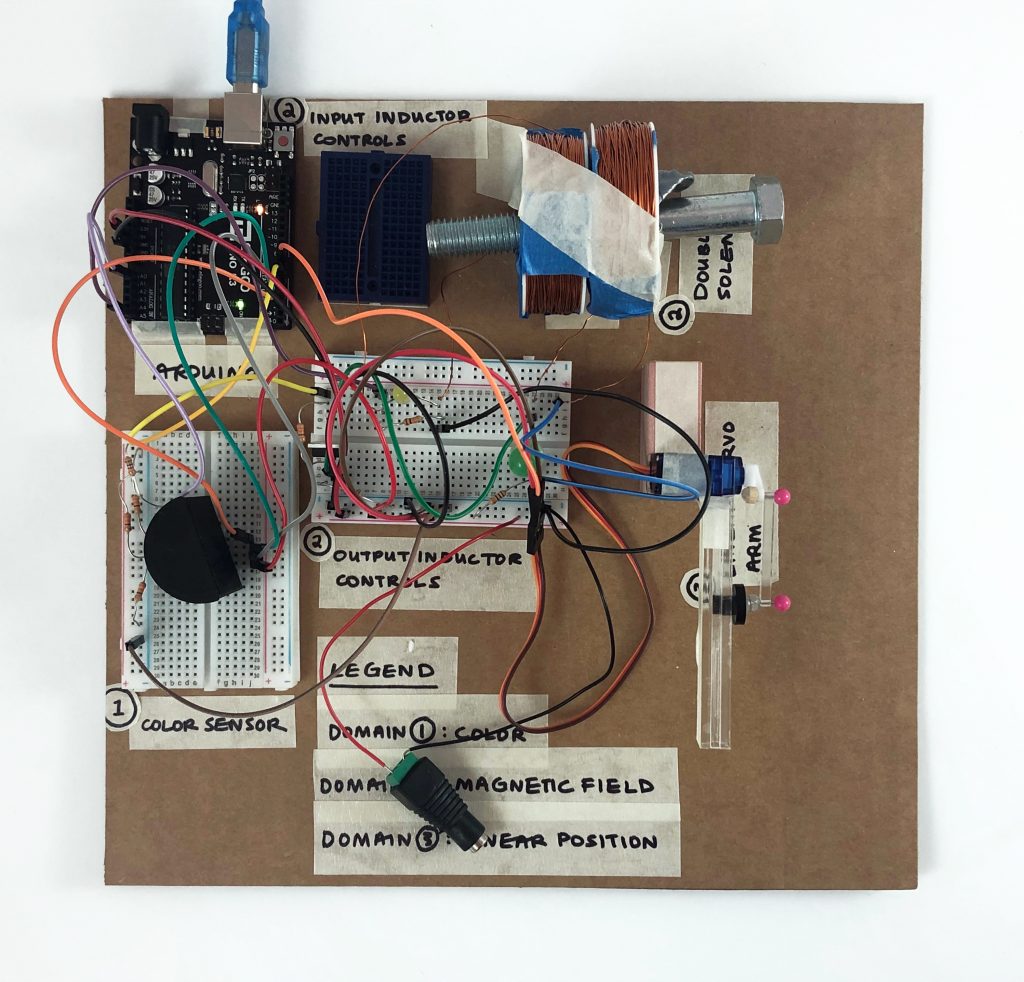
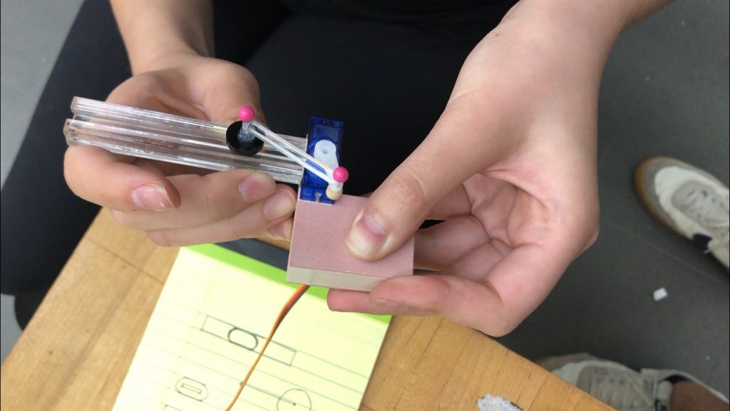
Overhead shot of the double transducer. The main components are labelled with names and numbers 1-3 which correspond to the order by which things are transduced.
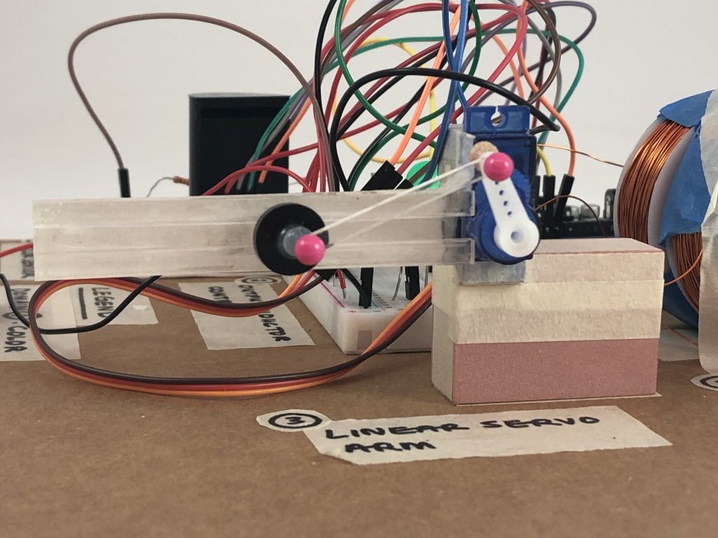
Servo motor arm close-up. The black pin moves linearly along the track. The pieces were laser cut and attached using pins and glue.
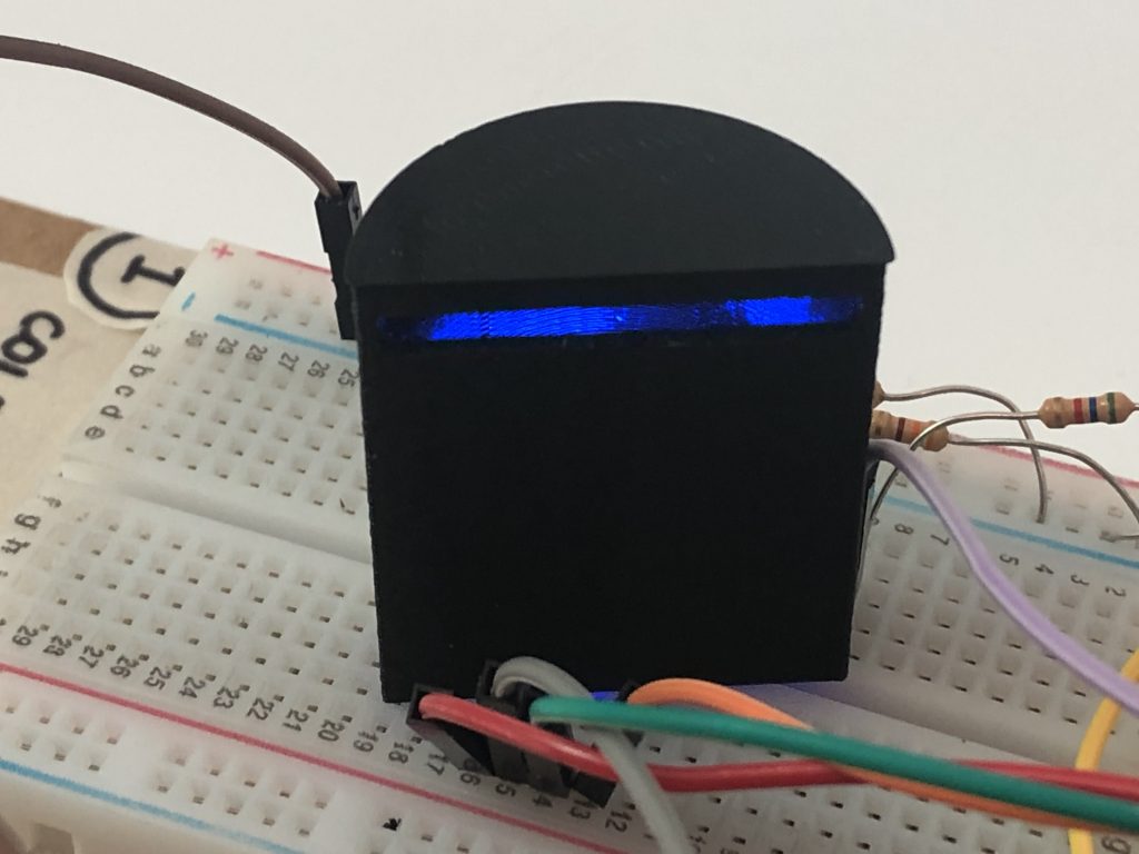
The DIY color sensor without the color insert. RGB LEDs flash in sequence inside the 3D printed cover. The blue LED is on in this instance.
The working sequence. The arm extends when the color sensor detects red; once the red coin is removed, the arm retracts.
Description: A power source powers a color sensor, which sends a signal to generate a magnetic field when it detects a change in color. The presence of a magnetic field will in turn cause the motor to turn, moving an arm linearly along a track.
Progress:
Here we are testing the range of the servo motor arm and the distance this translates to along the track.
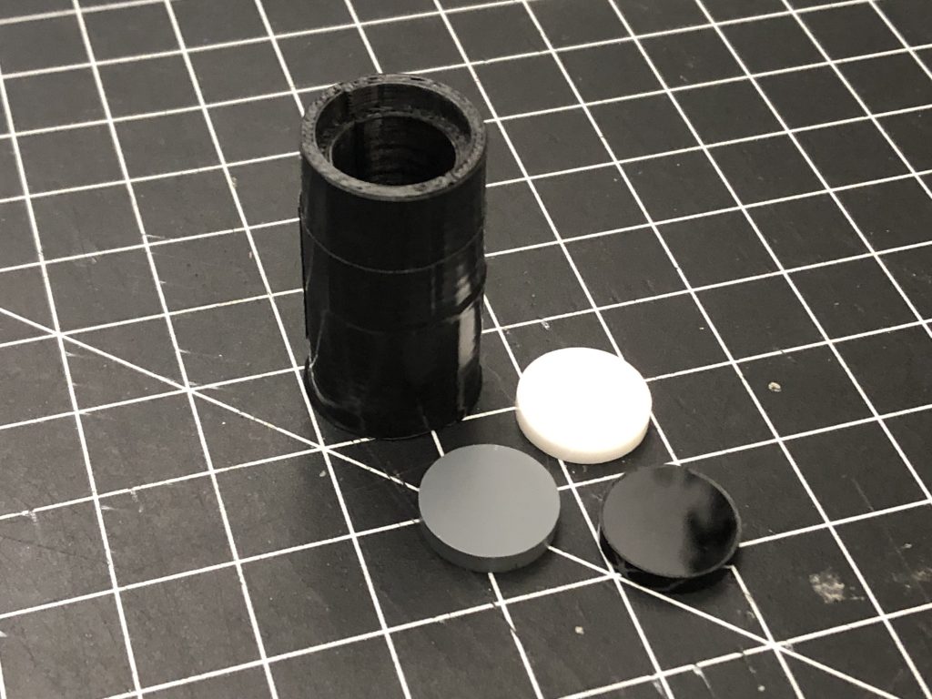
The failed first attempt at 3D printing a black-out cover for the color sensor. The tube was too small to cover the 3 LEDs and the photocell. We also chose red and yellow inserts for the final.
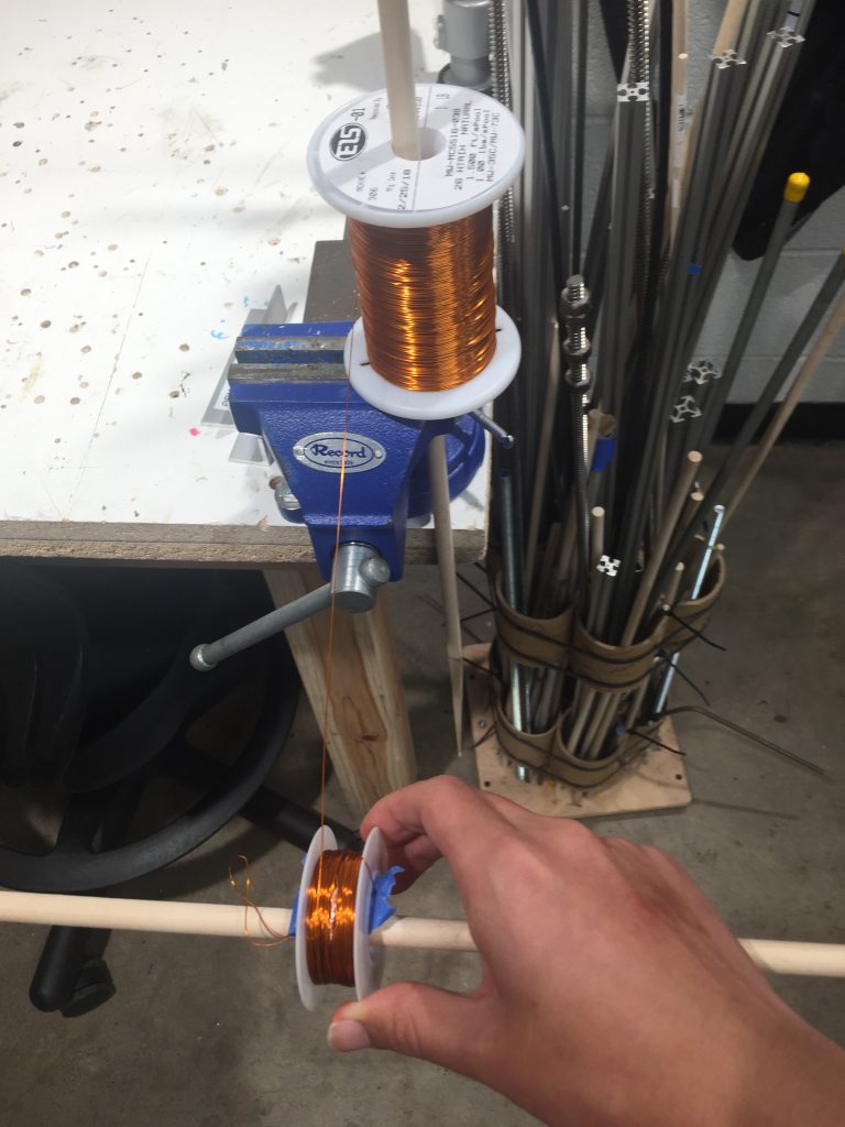
Wrapping copper wire to create the coils. This took some experimentation because we didn’t wrap around enough times in the first few attempts.
Discussion:
The makeshift RGB sensor worked surprisingly well after being wired up correctly, although the compact design increased the difficulty of properly wiring 3 LEDs and a photoresistor into the space of a little more than a square centimeter of space. The length of the legs of the LEDs were rather close, so at least one of the LEDs was inserted in the wrong direction initially. Despite minor problems, the RGB signal distinctly changed by about 100 for the red value after the red colored disk was inserted, which was a great success. However, it should be noted that the red signal was comparatively weaker, even with nothing else within the black casing, suggesting the possibility that the light from the previous LED isn’t given enough time to fade away. Admittedly, these were issues for the color sensor that weren’t predicted when designing the code and schematic from a purely theoretical perspective, but it did work as desired; this simple sensor exemplifies how valuable planning ahead was, yet it also reinforces how certain challenges might only be discovered in practice.
The solenoid system was neither simple or ended up working all too well. Numerous challenges arose, some from construction and others from human error. Although advice (thank you Zach for all the help with getting the solenoid circuits set up) and research produced circuits that would ideally work well with more powerful solenoids, the initial solenoid wire coils were initially only around a half-centimeter thick. So while the ‘drive coil’ (the coil that’s actively charged/discharged to produce a changing magnetic flux) could produce a tangible ‘pulse’ in a ceramic magnet disc held nearby, no signal could be detected in the receiving coil. After expanding the wire coils to a thickness of well over a centimeter, there still appeared to be no readable signal. This time it was due in part how the code, written beforehand, had used ‘digitalRead()’ instead of ‘analogRead()’, which made it impossible to detect the weak signal. Irregularities with how the Arduino was powered also interfered with consistent results. Overall, this experimental feature was a unique experience to test an unconventional signal transduction method and presented its fair share of challenges. Exercising good caution in design prevented any accidents from happening, though it might’ve been better to remove an existing coil from some motor or other component that was already wrapped and saved that time.
The linear motion servo made for little difficulty on the coding end since a library was available to easily interface with the device, requiring just a little calibration. Coming up with a design to convert its rotation to linear motion and constructing the largely mechanical instead of electrical component was another matter.
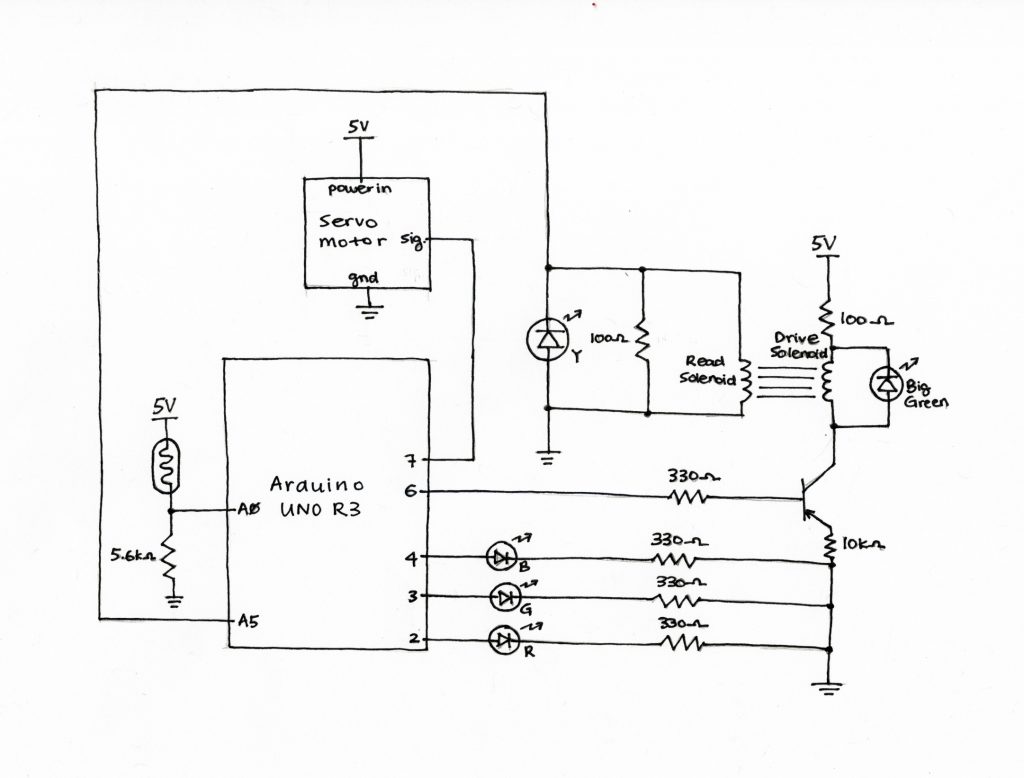
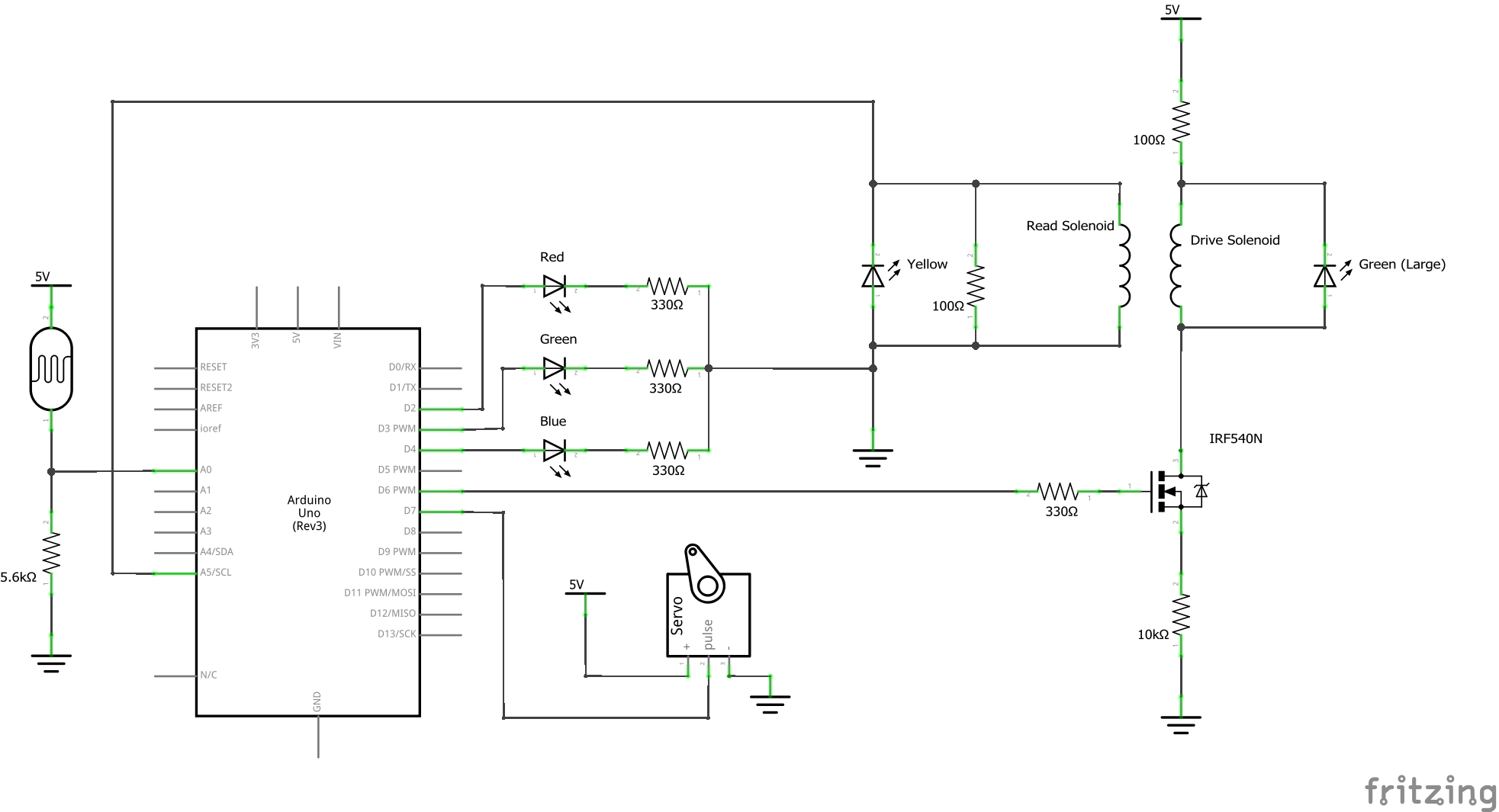
Schematic:
Code:
/* Project 1: Double Transducer

   Description: This code detects a color signal with a photoresistor and RGB LEDs, transmits that signal across two inductors,
   and passes out a 'positive' signal by driving a servo arm to extend a linear motion device.

   Resources Referenced:
   https://www.arduino.cc/reference/en/
   http://www.physics-and-radio-electronics.com/electronic-devices-and-circuits/rectifier/bridgerectifier.html
   https://create.arduino.cc/projecthub/mjrobot/arduino-color-detection-57e4ce?ref=tag&ref_id=color-detector&offset=0
   https://www.instructables.com/id/How-to-Control-an-Electromagnet-with-an-Arduino/

   Outputs
   Arduino Pin | Output
   2              Red LED
   3              Green LED
   4              Blue LED
   6              Output inductor Pin
   7              Servo Pin

   Input
   Arduino Pin | Input
   A0            Photoresistor
   A5            Input inductor Pin
*/

#include <Servo.h>

//Linear Motion
const int SERVO_PIN = 7; //OUTPUT, digital. Servo control pin.

const unsigned int rPeriod = 1000; //Parameter: refractory period for servo. Time for which a change to servo state cannot be changed again.

Servo arm; //Servo 'object'

bool moveConfirmed = false; //UTILITY: when true, arm extends at the end of the next refractory period, otherwise it'll retract
unsigned long lastmove = 0; //UTILITY: counter to determine time until refractory ends

//magnetic domain
const int O_MAG_PIN = 6; //OUTPUT, digital. Controls transistor powering the inductor.
const int I_MAG_PIN = A5; //INPUT, analog. Reads the read inductor

//magnetic domain: output
const unsigned long togThresh = 300; //PARAMETER, toggle output frequency in milliseconds. This determines how frequently the output inductor produces flux when it is permitted to do so.

unsigned long lasttoggle = 0; //UTILITY, toggle: Time since magnet signal was last toggled on/off. Only when the magnet is toggled
bool toggle = true; //UTILITY, toggle: used to determine which toggle step, on or off.

//magetic domain: input
const int thresh = 200; //UTILITY, minimum signal from the input pin from the inductor classified as a read
const int readTime = 200; //UTILITY, milliseconds taken by the entire read step
const int readFrq = 20; //UTILITY, number of times reads are taken in the

//Color Sensor
//(light detector)
const int PHOTO_PIN = A0; //INPUT, analog. Photoresistor pin. Signal corresponds to light level.
//(LED colors)
const int R_LED_PIN = 2; //OUTPUT, digital. RED LED pin, flashes first in series.
const int G_LED_PIN = 3; //OUTPUT, digital. GREEN LED pin, flashes second in series.
const int B_LED_PIN = 4; //OUTPUT, digital. BLUE LED pin, flashes last in series.

int target[3] = {300, 460, 230}; //PARAMETER for the RED  disk, must be calibrated based on lighting levels
//NOTE: Pervious testing values: casing has a color of about (195, 380, 295). RED side has about (270, 400, 250)

const int tolerance = 15; //UTILITY, +/- range that color matches target
int color[3]; //UTILITY, virtual RGB container variable representing the reflected color data

void setup() {
  // put your setup code here, to run once:
  //For debugging and viewing the inductor receiving signal
  Serial.begin(19200);

  //Linear Motion
  //OUTPUT
  arm.attach(SERVO_PIN);

  //Magnetic domain
  //INPUT
  pinMode(I_MAG_PIN, INPUT);
  //OUTPUT
  pinMode(O_MAG_PIN, OUTPUT); //To transistor


  //Color Sensor
  //INPUT
  pinMode(PHOTO_PIN, INPUT);
  //OUTPUT
  pinMode(R_LED_PIN, OUTPUT);
  pinMode(G_LED_PIN, OUTPUT);
  pinMode(B_LED_PIN, OUTPUT);

  delay(1000); //wait for the servo arm, as there may be cases where the signal is immediately present as soon as loop goes through
}

void loop() {
  // put your main code here, to run repeatedly:

  //Perform detection: check if RGB has changed enough to match some signal color
  colorRead(100); //Color detection; values stored in global array with a delay of 100 between each color.

  //Debugging line: Color input
  Serial.println((String)(color[0]) + " " + (String)(color[1]) + " " + (String)(color[2]));

  //if condition is met, power the inductor
  if (inThreshold()) {
    driveInductor();
  }

  //read the receivor inductor and confirm it has moved
  moveConfirmed = moveConfirmed || readInductor();

  //Attempts to move servo arm. Only proceeds if the refractory period has passed
  moveServoArm();
}

//move servo arm out and in
void moveServoArm() {
  //whenever the refractory period has passed, the arm is allowed to move again
  if (millis() - lastmove > rPeriod) {
    //moves arm when enough time has passed
    arm.write((moveConfirmed) ? 60 : 5); //If a move signal is measured at this step, move the arm out, otherwise pull it back in.
    lastmove = millis();
    moveConfirmed = false;
  }
}

//charge and discharge inductor to produce a varying flux
void driveInductor() {
  //if time since last toggle exceeds the threshold, toggle the inductor drive pin
  if (abs(millis() - lasttoggle) > togThresh) {
    digitalWrite(O_MAG_PIN, (toggle) ? HIGH : LOW);
    lasttoggle = millis();
    toggle = !toggle;
  }

}

//indicates whether there is substantial voltage induced from changing flux in the read inductor
bool readInductor() {
  //records if the signal ever exceeds a threshold
  bool successfulRead = false;
  for (int i = 0; i < readFrq; i++) {
    int fluxread = analogRead(I_MAG_PIN);
    //Debugging: Flux measurement results
    //Serial.println(fluxread);

    //checks if signal exceeds a threshold.
    successfulRead = successfulRead || fluxread > thresh;

    delay(readTime / readFrq); //divides the delay time into readFrq number of segments for a total of readTime worth of time

  }
  return successfulRead;
}

//Checks if light is within the threshold of being a target
bool inThreshold() {
  //loops for 1,2,3 or RGB to check all values are within tolerance threshold
  for (int i = 0; i < 3; i++) {
    if (abs(target[0] - color[0]) > tolerance)return false;
  }
  //if for no color it returns false, then all colors are in tolerance
  return true;
}

//Checks color by flashing each RGB LED color for reflection from chamber and sets value in color array
//frq variable used to control delay between reads, or the speed of the flashes.
//In theory, a longer delay would result in higher accuracy but sacrifice responsiveness and speed
void colorRead(int frq) {
  setLED(0); //reset to no LEDs
  setLED(1); //RED LED ON
  delay(frq);
  color[0] = analogRead(PHOTO_PIN); //read RED
  setLED(0);
  setLED(2); //GREEN LED ON
  delay(frq);
  color[1] = analogRead(PHOTO_PIN); //read GREEN
  setLED(0);
  setLED(3); //BLUE LED ON
  delay(frq);
  color[2] = analogRead(PHOTO_PIN); //read BLUE
  setLED(0);
}

//Sets the LEDs on/off based on a key value. A switch case might work even better, but this function is still perfectly functional.
void setLED(int key) {
  if (key == 0) {
    digitalWrite(R_LED_PIN, LOW);
    digitalWrite(G_LED_PIN, LOW);
    digitalWrite(B_LED_PIN, LOW);
  }
  else if (key == 1)digitalWrite(R_LED_PIN, HIGH);
  //else digitalWrite(R_LED_PIN,LOW);
  else if (key == 2)digitalWrite(G_LED_PIN, HIGH);
  //else digitalWrite(G_LED_PIN,LOW);
  else if (key == 3)digitalWrite(B_LED_PIN, HIGH);
  //else digitalWrite(B_LED_PIN,LOW);
}
Comments are closed.