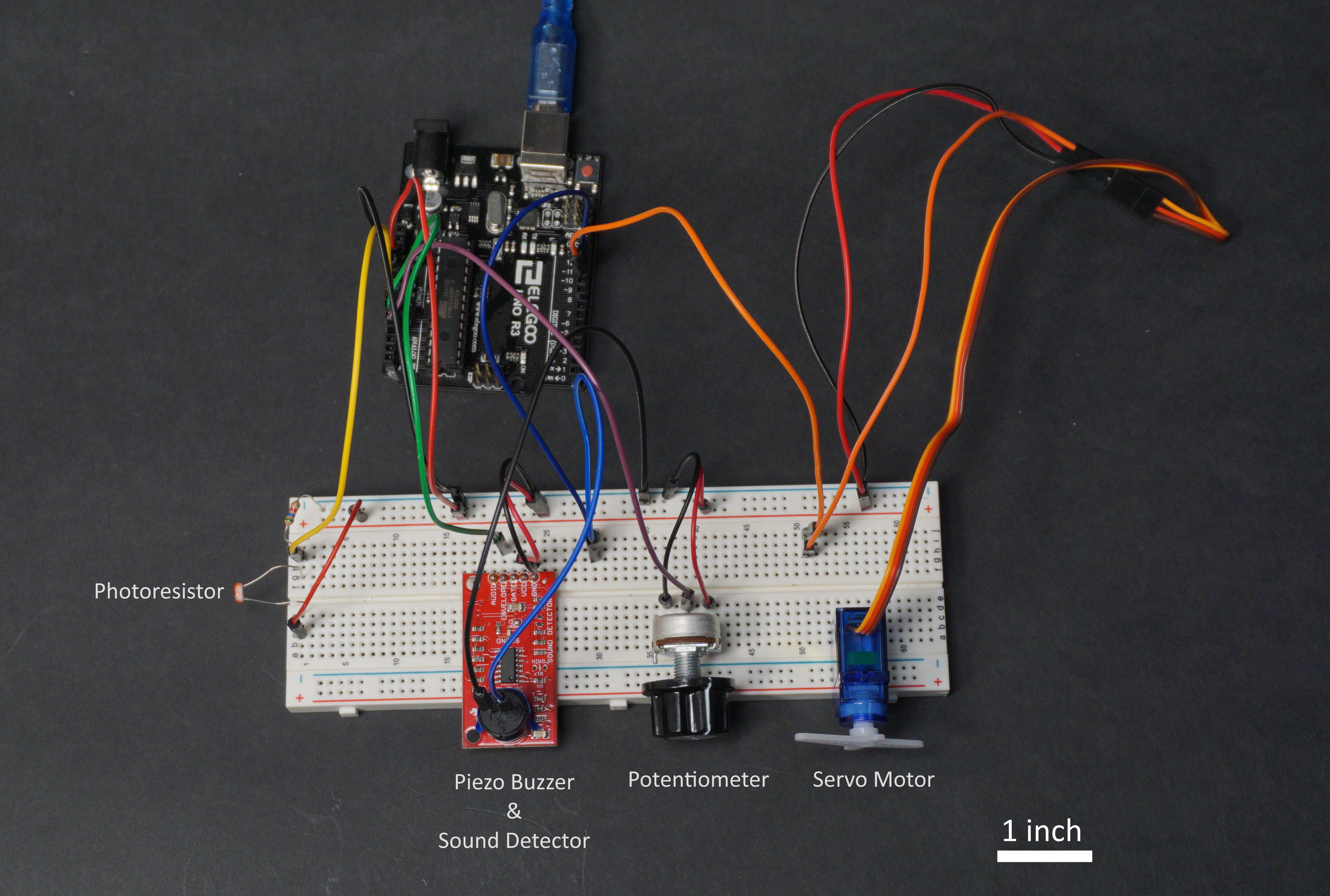
Overhead view of the double transducer with parts labeled and scale included.
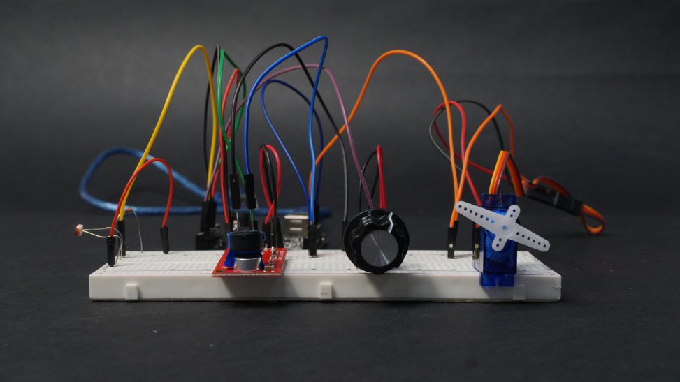
Side view of the transducer. The signal is transduced from the front-left to the back-right.
Demo video showing the operation of the transducer. The knob is used to adjust to the increasing brightness.
Description
Our double transducer uses a photoresistor to translate light to sound. If the amount of light detected goes over a threshold set by the user using the knob, a buzzer will sound. The duration of the sound then determines how much the servo motor rotates.
Progress
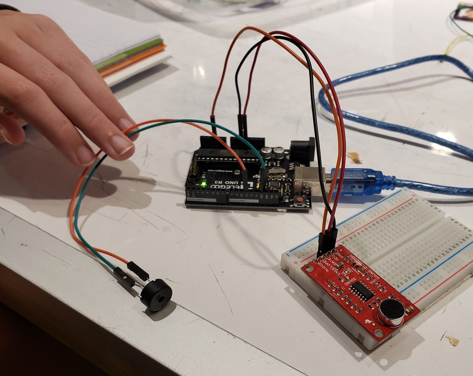
Testing the I/O of the sound domain. This allowed us to determine a value for the volume threshold.
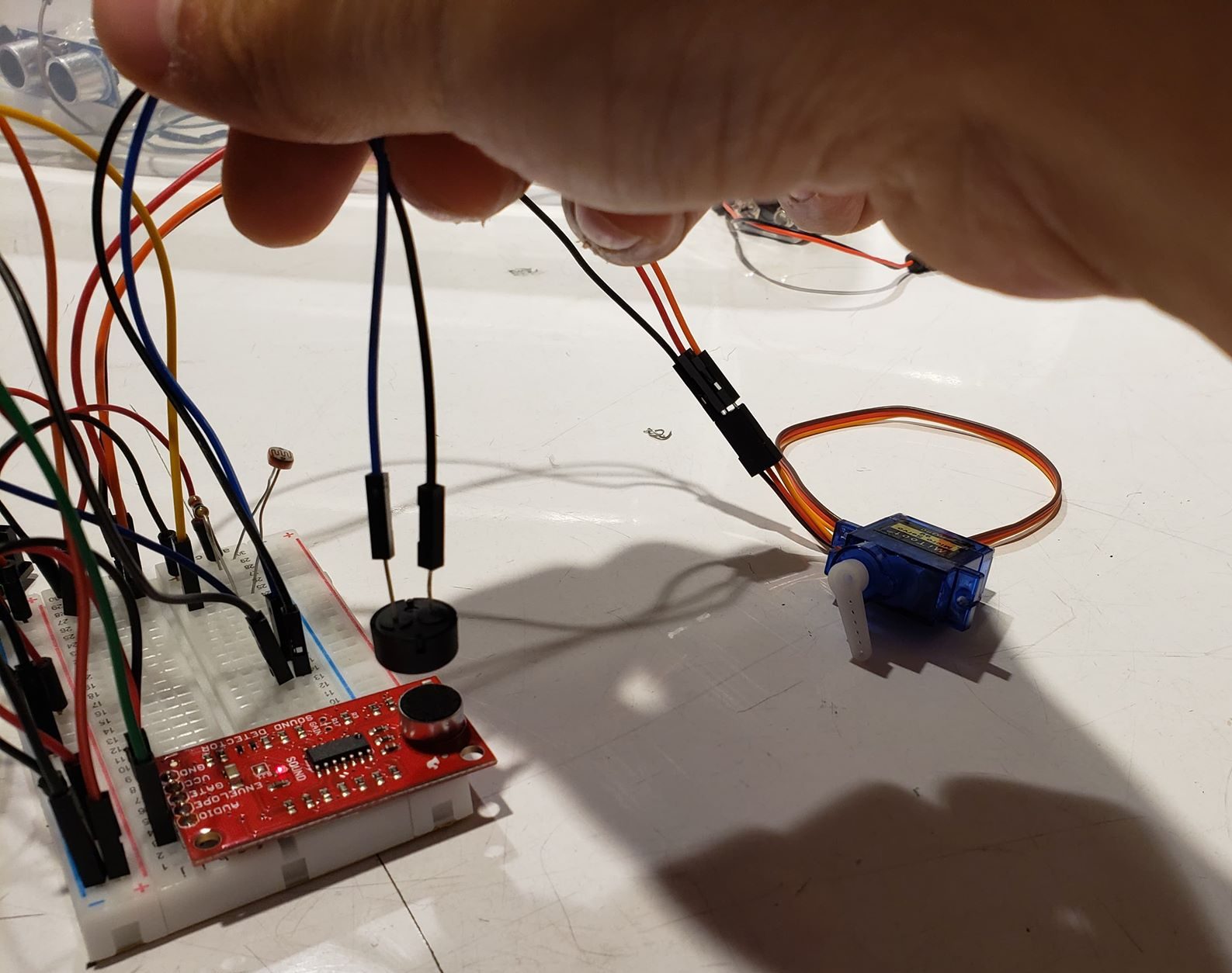
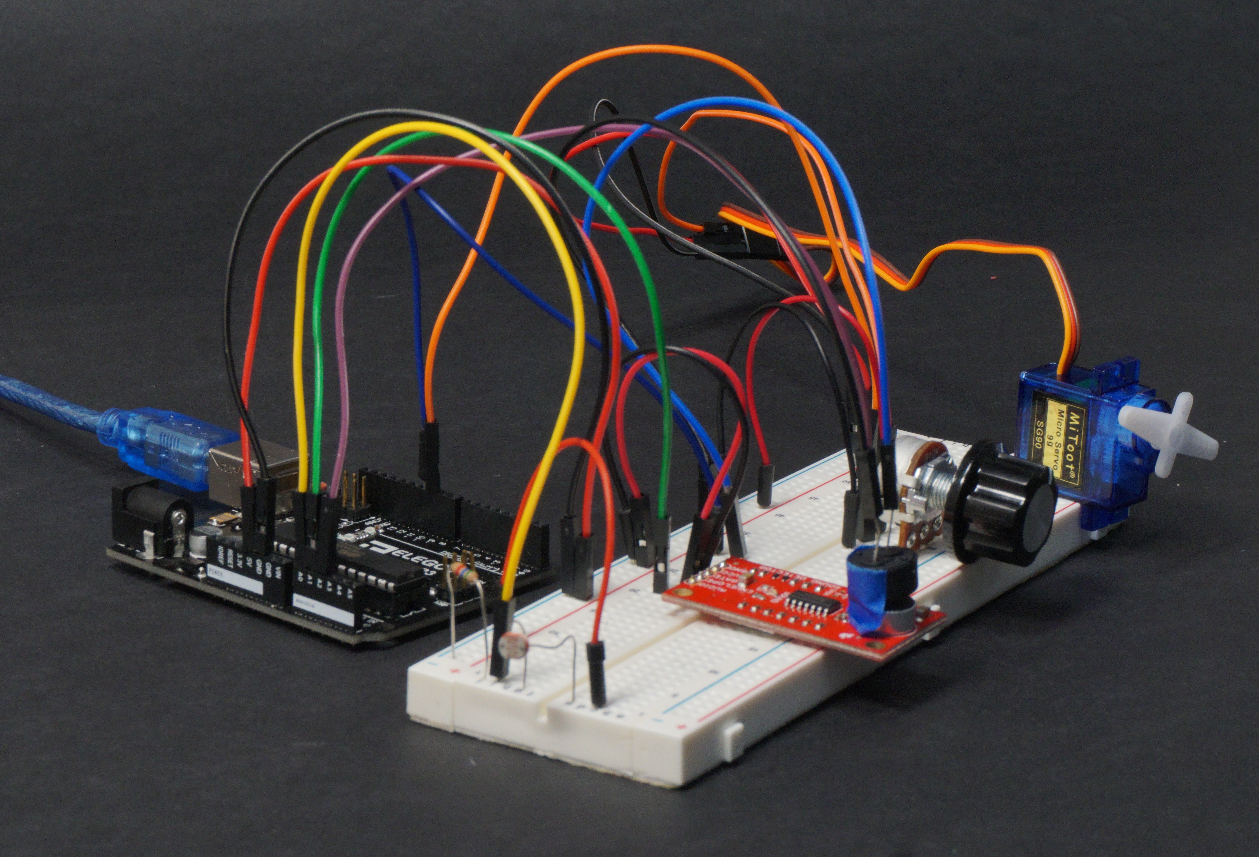
Initial wiring of the transducer. The cluttering made it difficult to debug our wiring issues.
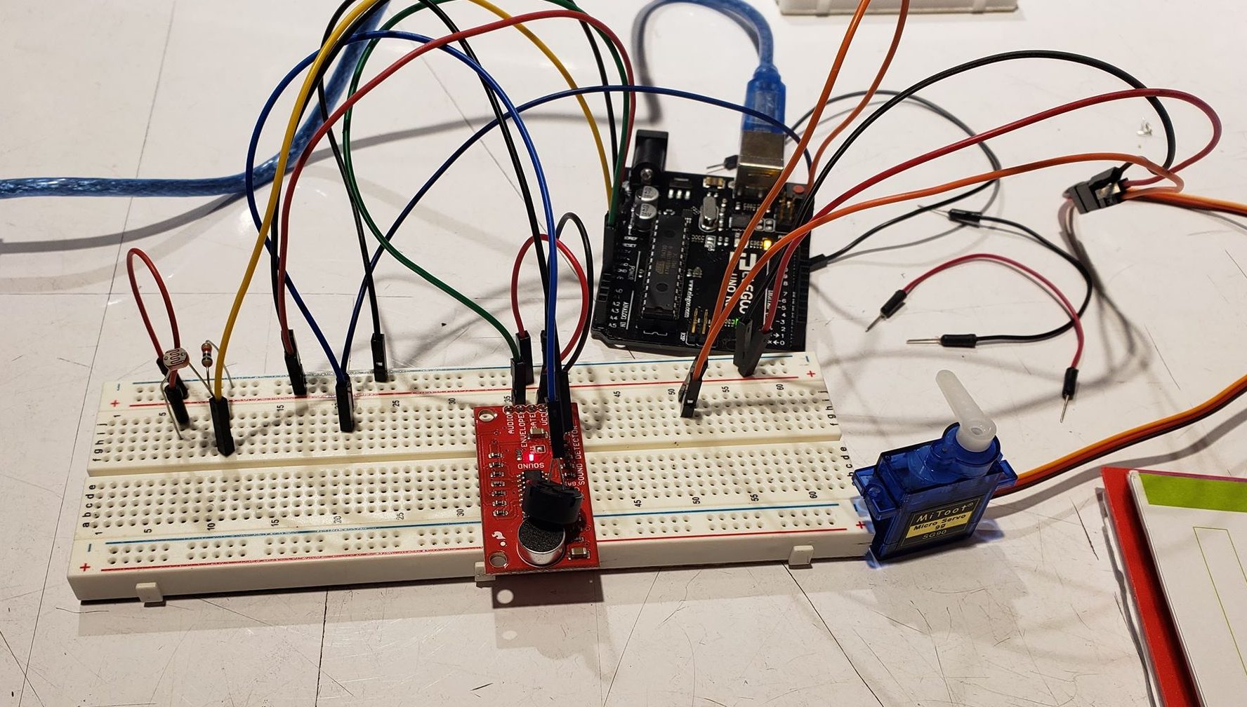
We migrated to a larger breadboard to make the wiring more straightforward and organized the components by medium. The photoresistor (light) is on the left, the buzzer and sound detector in the middle, and the the servo (rotation) is on the right.
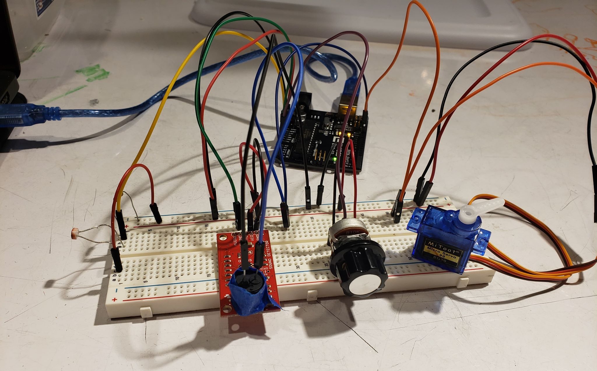
The final version required tape to secure the buzzer to the sound detector. This also reduced the interference of ambient noise.
Discussion
We initially planned to have the buzzer output a different volume depending on how bright the light was. We decided not to go this direction because we weren’t sure how to vary the voltage going into the buzzer in order to change the volume, and the amplitude sensor was pretty noisy. It also wouldn’t have worked well with the input since the group with light as an output didn’t vary the brightness of their LED, it was either on or off. We decided to change our approach and make the buzzer sound while the LED was on, since this would work better with the other group’s output and would be easier to detect with the sound detector.
Instead of intensity, we translated light to angular motion using time. This meant that we needed to make several decisions regarding the input/output of the three domains:
- The threshold light value to turn the buzzer on. This will be dependent on the ambient light of the room and the previous group’s light intensity.
- The volume threshold for the sound detector to consider the buzzer as on. This needs to be high enough to filter out the ambient noise, but low enough to not ignore the buzzer.
- The maximum anticipated duration of a buzzer sound. This will determine how responsive the servo is to changes in duration.
Wiring the circuit was fairly straightforward, but we had some trouble with the photoresistor. The analog input we read did not match our expectations, and we realized that it was most likely a wiring issue. We rewired the components in a different position on the board, and this fixed the problem. We believe that either we had originally connected the resistor to the wrong location.
Despite the fact that neither of us had worked with a sound detector before, it was fairly easy to wire up because the on-board electronics handle most of the audio signal processing. We were able to use the serial plotter to determine which input from the sound detector would be best for our project. We decided to use the envelope pin, which outputs the “volume” as an analog signal, and using the serial monitor we decided on a threshold volume. We did notice that the signal can be noisy, so we also added a minimum duration threshold for the servo to be triggered.
Something we added on towards the end was a potentiometer to set the threshold value for the photoresistor. This allowed us to adjust for the ambient light of the room as we were chaining up our transducer with the other group’s. It wasn’t much trouble to add it on, but we should have considered it when planning our project. If our circuit was more complicated, it might’ve been harder to add something in. Unfortunately, we did not make the maximum light duration value dynamically adjustable, which meant that we still needed to modify and re-upload a couple of times until our anticipated values matched the previous group’s actual light duration.
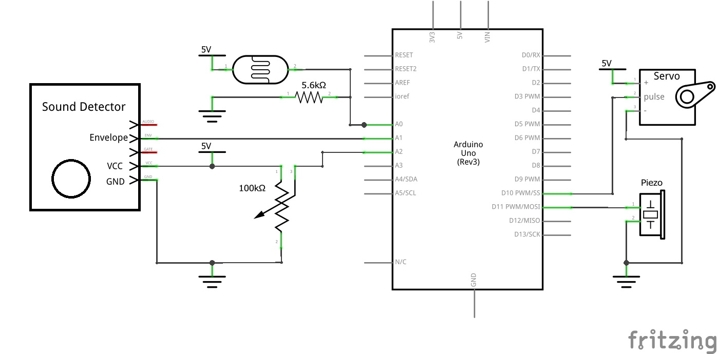
Schematic
Code
- <span class="com">/*
- * Project 1: Light -> Sound -> Rotation Double Transducer
- *
- * Description: A transducer that translates light from a
- * photoresistor into sound, and output the duration
- * of the sound as an angle [0, 180] on a servo motor
- *
- * Inputs: Switch, button, potentiometer, photoresistor
- * Arduino pin | input
- * A2 Potentiometer (Adjust light threshold)
- * A1 Sound Detector
- * A0 Photoresistor
- *
- * Outputs: Speaker, serial, servo
- * Arduino pin | output
- * 11 Piezo Buzzer
- * 10 Servo
- *
- */</span><span class="pln">
- </span><span class="com">#include</span><span class="pln"> </span><span class="str"><Servo.h></span><span class="pln">
- </span><span class="kwd">const</span><span class="pln"> </span><span class="kwd">int</span><span class="pln"> POT_PIN </span><span class="pun">=</span><span class="pln"> A2</span><span class="pun">;</span><span class="pln">
- </span><span class="kwd">const</span><span class="pln"> </span><span class="kwd">int</span><span class="pln"> SOUND_PIN </span><span class="pun">=</span><span class="pln"> A1</span><span class="pun">;</span><span class="pln">
- </span><span class="kwd">const</span><span class="pln"> </span><span class="kwd">int</span><span class="pln"> PHOTO_PIN </span><span class="pun">=</span><span class="pln"> A0</span><span class="pun">;</span><span class="pln">
- </span><span class="kwd">const</span><span class="pln"> </span><span class="kwd">int</span><span class="pln"> SERVO_PIN </span><span class="pun">=</span><span class="pln"> </span><span class="lit">10</span><span class="pun">;</span><span class="pln">
- </span><span class="kwd">const</span><span class="pln"> </span><span class="kwd">int</span><span class="pln"> BUZZER_PIN </span><span class="pun">=</span><span class="pln"> </span><span class="lit">11</span><span class="pun">;</span><span class="pln">
- </span><span class="com">//Threshold for detecting if buzzer is on</span><span class="pln">
- </span><span class="kwd">const</span><span class="pln"> </span><span class="kwd">int</span><span class="pln"> VOL_THRESHOLD </span><span class="pun">=</span><span class="pln"> </span><span class="lit">300</span><span class="pun">;</span><span class="pln">
- </span><span class="com">//Threshold ranges for the light/sound durations (ms)</span><span class="pln">
- </span><span class="kwd">const</span><span class="pln"> </span><span class="kwd">int</span><span class="pln"> MIN_TIME </span><span class="pun">=</span><span class="pln"> </span><span class="lit">50</span><span class="pun">;</span><span class="pln">
- </span><span class="kwd">const</span><span class="pln"> </span><span class="kwd">int</span><span class="pln"> MAX_TIME </span><span class="pun">=</span><span class="pln"> </span><span class="lit">400</span><span class="pun">;</span><span class="pln">
- </span><span class="kwd">unsigned</span><span class="pln"> </span><span class="kwd">long</span><span class="pln"> time</span><span class="pun">;</span><span class="pln">
- </span><span class="typ">Servo</span><span class="pln"> servo</span><span class="pun">;</span><span class="pln">
- </span><span class="kwd">void</span><span class="pln"> setup</span><span class="pun">()</span><span class="pln"> </span><span class="pun">{</span><span class="pln">
- </span><span class="typ">Serial</span><span class="pun">.</span><span class="kwd">begin</span><span class="pun">(</span><span class="lit">9600</span><span class="pun">);</span><span class="pln">
- pinMode</span><span class="pun">(</span><span class="pln">SOUND_PIN</span><span class="pun">,</span><span class="pln"> INPUT</span><span class="pun">);</span><span class="pln">
- pinMode</span><span class="pun">(</span><span class="pln">PHOTO_PIN</span><span class="pun">,</span><span class="pln"> INPUT</span><span class="pun">);</span><span class="pln">
- pinMode</span><span class="pun">(</span><span class="pln">BUZZER_PIN</span><span class="pun">,</span><span class="pln"> OUTPUT</span><span class="pun">);</span><span class="pln">
- servo</span><span class="pun">.</span><span class="pln">attach</span><span class="pun">(</span><span class="pln">SERVO_PIN</span><span class="pun">);</span><span class="pln">
- </span><span class="pun">}</span><span class="pln">
- </span><span class="kwd">void</span><span class="pln"> loop</span><span class="pun">()</span><span class="pln"> </span><span class="pun">{</span><span class="pln">
- </span><span class="kwd">int</span><span class="pln"> brightnessVal </span><span class="pun">=</span><span class="pln"> analogRead</span><span class="pun">(</span><span class="pln">PHOTO_PIN</span><span class="pun">);</span><span class="pln">
- </span><span class="com">// Adjust potentiometer to calibrate what is ambient light</span><span class="pln">
- </span><span class="com">// and what brightness will turn on the buzzer.</span><span class="pln">
- </span><span class="kwd">int</span><span class="pln"> lightThreshold </span><span class="pun">=</span><span class="pln"> analogRead</span><span class="pun">(</span><span class="pln">POT_PIN</span><span class="pun">);</span><span class="pln">
- </span><span class="com">// Turn buzzer on if light is above threshold</span><span class="pln">
- </span><span class="kwd">if</span><span class="pln"> </span><span class="pun">(</span><span class="pln">brightnessVal </span><span class="pun">></span><span class="pln"> lightThreshold</span><span class="pun">)</span><span class="pln"> </span><span class="pun">{</span><span class="pln">
- tone</span><span class="pun">(</span><span class="pln">BUZZER_PIN</span><span class="pun">,</span><span class="pln"> </span><span class="lit">440</span><span class="pun">);</span><span class="pln">
- </span><span class="pun">}</span><span class="pln"> </span><span class="kwd">else</span><span class="pln"> </span><span class="pun">{</span><span class="pln">
- noTone</span><span class="pun">(</span><span class="pln">BUZZER_PIN</span><span class="pun">);</span><span class="pln">
- </span><span class="pun">}</span><span class="pln">
- </span><span class="com">// If sound stopped on this loop, calculate how long sound</span><span class="pln">
- </span><span class="com">// had previously been on</span><span class="pln">
- </span><span class="kwd">unsigned</span><span class="pln"> </span><span class="kwd">long</span><span class="pln"> elapsed </span><span class="pun">=</span><span class="pln"> </span><span class="lit">0</span><span class="pun">;</span><span class="pln">
- </span><span class="kwd">if</span><span class="pun">(</span><span class="pln">analogRead</span><span class="pun">(</span><span class="pln">SOUND_PIN</span><span class="pun">)</span><span class="pln"> </span><span class="pun"><</span><span class="pln"> VOL_THRESHOLD</span><span class="pun">)</span><span class="pln"> </span><span class="pun">{</span><span class="pln">
- elapsed </span><span class="pun">=</span><span class="pln"> millis</span><span class="pun">()</span><span class="pln"> </span><span class="pun">-</span><span class="pln"> time</span><span class="pun">;</span><span class="pln">
- time </span><span class="pun">=</span><span class="pln"> millis</span><span class="pun">();</span><span class="pln">
- </span><span class="pun">}</span><span class="pln">
- </span><span class="com">//Use the serial plotter to help calibrate against ambient light</span><span class="pln">
- </span><span class="typ">Serial</span><span class="pun">.</span><span class="kwd">print</span><span class="pun">(</span><span class="pln">brightnessVal</span><span class="pun">);</span><span class="pln">
- </span><span class="typ">Serial</span><span class="pun">.</span><span class="kwd">print</span><span class="pun">(</span><span class="str">" "</span><span class="pun">);</span><span class="pln">
- </span><span class="typ">Serial</span><span class="pun">.</span><span class="pln">println</span><span class="pun">(</span><span class="pln">lightThreshold</span><span class="pun">);</span><span class="pln">
- </span><span class="com">//Rotate servo arm based on duration</span><span class="pln">
- </span><span class="kwd">if</span><span class="pln"> </span><span class="pun">(</span><span class="pln">elapsed </span><span class="pun">></span><span class="pln"> MIN_TIME</span><span class="pun">)</span><span class="pln"> </span><span class="pun">{</span><span class="pln">
- servo</span><span class="pun">.</span><span class="pln">write</span><span class="pun">(</span><span class="pln">map</span><span class="pun">(</span><span class="pln">elapsed</span><span class="pun">,</span><span class="pln"> </span><span class="lit">0</span><span class="pun">,</span><span class="pln"> MAX_TIME</span><span class="pun">,</span><span class="pln"> </span><span class="lit">0</span><span class="pln"> </span><span class="pun">,</span><span class="lit">180</span><span class="pun">));</span><span class="pln">
- </span><span class="pun">}</span><span class="pln">
- </span><span class="pun">}</span>
Comments are closed.