
Double transducer: rotation to magnetic field
Title: Double Transducer – Rotation to Magnetic Field
Description:
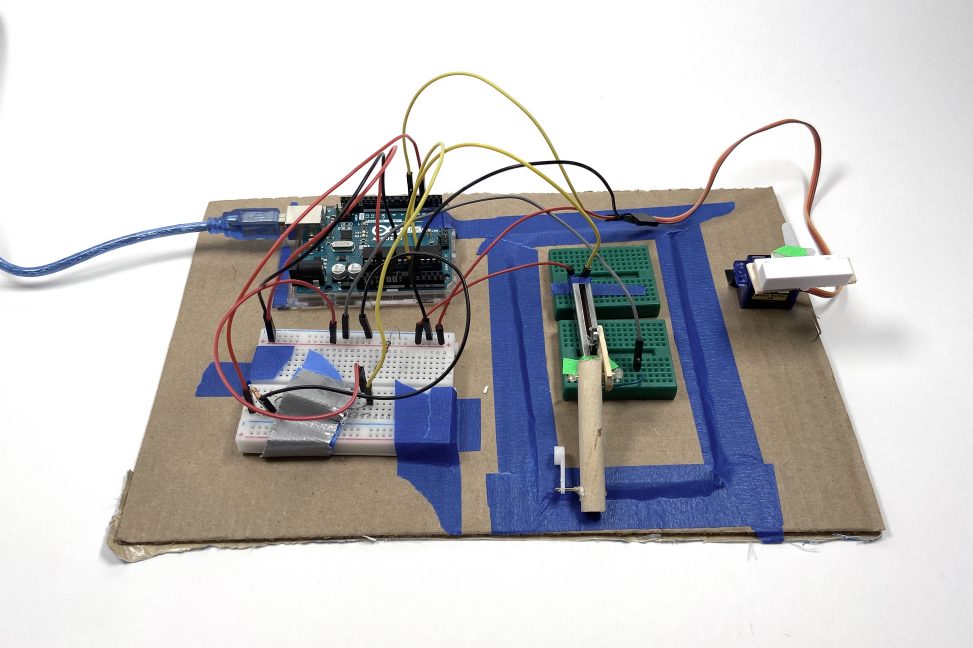
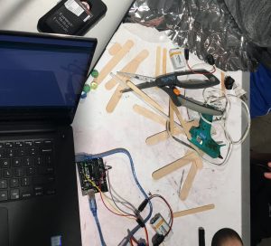
Our group has the input domain of rotation, and an output domain of magnetic field. We decided to use the middle domain as light. A small servo motor is attached to a mechanism that moves the slider of a linear potentiometer. The potentiometer is connected to an LED which gets brighter and dimmer. The LED is placed closed to a photo resistor. If the resistance value is higher than a certain set point, the servometer with the magnet attached moves to a 175 degree angle. If it is less than the set point, it moves to a 0 degree angle. The magnet on the servo motor constantly gets rotated to face another magnet, which creates a magnetic field. When the servo motor is rotated away from the magnet, there is no magnetic field.
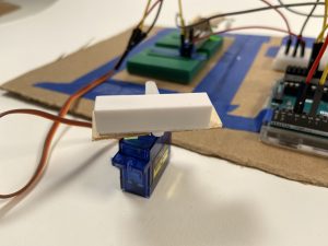
The magnet attached to the servomotor to create a magnetic field.
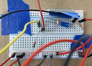
The LED is positioned right up to the photoresistor for the best reading of values underneath the tape.
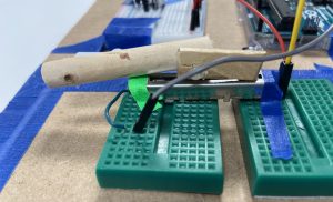
The mechanism that converts rotational movement into linear movement is attached to a potentiometer.
Rotation to magnetic field double transducer.
Process:
Our first attempt using popsicles sticks to create the mechanism that converts rotational movement into linear movement. It failed many times.
Revising the mechanism to become simpler and less fragile.
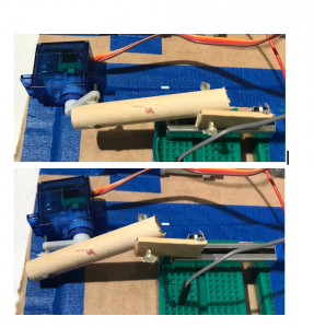
Success! The rotation-to-linear movement mechanism at two different positions.
Discussion:
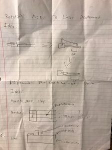
An important problem that we needed to solve as a team was converting the rotation of the incoming servo motor to an analog electronic signal. We found that the most effective way to achieve this was through a rotational to linear converter. The servo arm was attached to a linear sliding variable resistor with a rigid arm . The arm had the ability to rotate freely so that the arm could always be attached to both points, and the rotation of the servo will push and pull the resistor, changing the voltage value in a voltage divider.
Interfacing electronics with the physical domain was a challenging part of our project. This was apparent when incorporating the linear sliding potentiometer. Originally, a popsicle stick casing was created to fix the potentiometer, but the hot glue used broke the electronic component. To solve this problem, we placed the potentiometer in a breadboard, and applied force at an angle that would not remove it. For future projects we will consider the fragility of electronics components before hand to save time and effort.
One of the more difficult parts was to get a clear relationship between the changing rotation input and the magnetic field output. We had imagined that the photoresistor would have resistance values that would be mappable directly to the rotation of the end servomotor. However, the readings on the photoresistor were very noisy. We tried to eliminate external lights using tape. The servomotor would twitch to angles that seemed random. It made it difficult to tell the relationship between the input rotation and the output rotation. Therefore we decided to divide the values from the photoresistor according to a certain setpoint. The result may be a little less fun than having a range of values, but we think it makes for a clearer system.
Another difficult part that is related to the point above is deciding what the set point should be. We had to test several points, which often had a result of the servometer and the end twitching constantly because the resistance values were stuck in between the points we had decided. When we had come to a conclusion of points that seemed to work, we learned that we had to make sure that the physical factors were all unchanging, for example the position of the LED and photoresistor, and the lighting of the environment we were in.
Schematic:
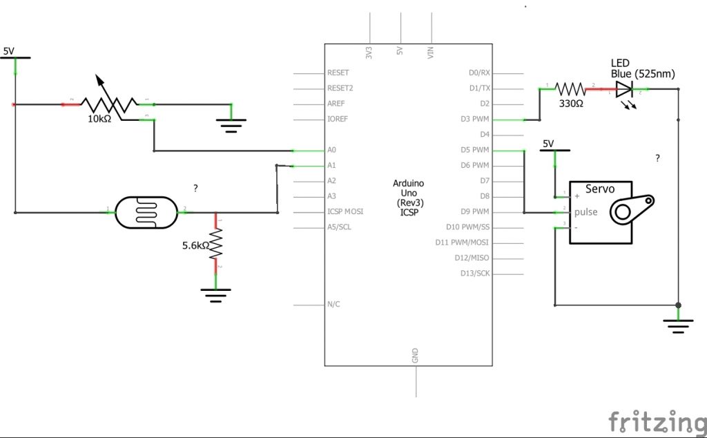
The schematic for this double transducer.
- <span class="com">/* Project: Rotation to Light to Magnetic Field Double Transducer
- *
- * Summary: Our code takes the input from a voltage divder
- * with a potentiometer and lights up an LED with a brightness determined
- * by the position of the potentiometer. A voltage divider with a
- * photoresistor sensing the light is read by the code, and a servo motor is
- * turned to one of two positions depending on the light level. The code
- * also prints the brightness and potentiometer value to the serial monitor
- * to make debugging easier
- *
- * Inputs:
- * Arduino pin | input
- * A0 sliding potentiometer
- * A1 photoresistor
- *
- * Outputs:
- * Arduino pin | output
- * 3 blue LED
- * 5 servo motor
- */</span><span class="pln">
- </span><span class="com">#include</span><span class="pln"> </span><span class="str"><Servo.h></span><span class="pln">
- </span><span class="com">//analog sensors</span><span class="pln">
- </span><span class="kwd">const</span><span class="pln"> </span><span class="kwd">int</span><span class="pln"> POT_PIN </span><span class="pun">=</span><span class="pln"> A0</span><span class="pun">;</span><span class="pln">
- </span><span class="kwd">const</span><span class="pln"> </span><span class="kwd">int</span><span class="pln"> PHOTO_PIN </span><span class="pun">=</span><span class="pln"> A1</span><span class="pun">;</span><span class="pln">
- </span><span class="com">//digital sensors</span><span class="pln">
- </span><span class="kwd">const</span><span class="pln"> </span><span class="kwd">int</span><span class="pln"> LED_PIN </span><span class="pun">=</span><span class="pln"> </span><span class="lit">3</span><span class="pun">;</span><span class="pln">
- </span><span class="kwd">const</span><span class="pln"> </span><span class="kwd">int</span><span class="pln"> SERVO_PIN </span><span class="pun">=</span><span class="pln"> </span><span class="lit">5</span><span class="pun">;</span><span class="pln">
- </span><span class="typ">Servo</span><span class="pln"> myServo</span><span class="pun">;</span><span class="pln"> </span><span class="com">// creates motor</span><span class="pln">
- </span><span class="kwd">void</span><span class="pln"> setup</span><span class="pun">()</span><span class="pln"> </span><span class="pun">{</span><span class="pln">
- </span><span class="com">//input pins</span><span class="pln">
- pinMode</span><span class="pun">(</span><span class="pln">POT_PIN</span><span class="pun">,</span><span class="pln"> INPUT</span><span class="pun">);</span><span class="pln">
- pinMode</span><span class="pun">(</span><span class="pln">PHOTO_PIN</span><span class="pun">,</span><span class="pln"> INPUT</span><span class="pun">);</span><span class="pln">
- </span><span class="com">//pin outputs</span><span class="pln">
- pinMode</span><span class="pun">(</span><span class="pln">LED_PIN</span><span class="pun">,</span><span class="pln"> OUTPUT</span><span class="pun">);</span><span class="pln">
- pinMode</span><span class="pun">(</span><span class="pln">SERVO_PIN</span><span class="pun">,</span><span class="pln"> OUTPUT</span><span class="pun">);</span><span class="pln">
- </span><span class="com">//attach servomotor </span><span class="pln">
- myServo</span><span class="pun">.</span><span class="pln">attach</span><span class="pun">(</span><span class="pln">SERVO_PIN</span><span class="pun">);</span><span class="pln">
- </span><span class="typ">Serial</span><span class="pun">.</span><span class="kwd">begin</span><span class="pun">(</span><span class="lit">9600</span><span class="pun">);</span><span class="pln">
- </span><span class="pun">}</span><span class="pln">
- </span><span class="kwd">void</span><span class="pln"> loop</span><span class="pun">()</span><span class="pln"> </span><span class="pun">{</span><span class="pln">
- </span><span class="kwd">int</span><span class="pln"> potVal </span><span class="pun">=</span><span class="pln"> analogRead</span><span class="pun">(</span><span class="pln">POT_PIN</span><span class="pun">);</span><span class="pln">
- </span><span class="typ">Serial</span><span class="pun">.</span><span class="pln">println</span><span class="pun">(</span><span class="pln">potVal</span><span class="pun">);</span><span class="pln">
- </span><span class="kwd">int</span><span class="pln"> </span><span class="typ">Brightness</span><span class="pln"> </span><span class="pun">=</span><span class="pln"> map</span><span class="pun">(</span><span class="pln">potVal</span><span class="pun">,</span><span class="pln"> </span><span class="lit">0</span><span class="pun">,</span><span class="pln"> </span><span class="lit">1023</span><span class="pun">,</span><span class="pln"> </span><span class="lit">0</span><span class="pun">,</span><span class="pln"> </span><span class="lit">255</span><span class="pun">);</span><span class="pln">
- analogWrite</span><span class="pun">(</span><span class="pln">LED_PIN</span><span class="pun">,</span><span class="pln"> </span><span class="typ">Brightness</span><span class="pun">);</span><span class="pln">
- </span><span class="kwd">int</span><span class="pln"> </span><span class="typ">BrightnessVal</span><span class="pln"> </span><span class="pun">=</span><span class="pln"> analogRead</span><span class="pun">(</span><span class="pln">PHOTO_PIN</span><span class="pun">);</span><span class="pln">
- </span><span class="typ">Serial</span><span class="pun">.</span><span class="pln">println</span><span class="pun">(</span><span class="typ">BrightnessVal</span><span class="pun">);</span><span class="pln">
- </span><span class="com">// motor responds to brightness level, the lack of a hard dividing point</span><span class="pln">
- </span><span class="com">// prevents rapid twitches in the servo. We picked these values experimentally through best judgement</span><span class="pln">
- </span><span class="kwd">if</span><span class="pln"> </span><span class="pun">(</span><span class="typ">BrightnessVal</span><span class="pln"> </span><span class="pun"><</span><span class="pln"> </span><span class="lit">400</span><span class="pun">)</span><span class="pln"> </span><span class="pun">{</span><span class="pln">
- myServo</span><span class="pun">.</span><span class="pln">write</span><span class="pun">(</span><span class="lit">5</span><span class="pun">);</span><span class="pln">
- </span><span class="pun">}</span><span class="pln">
- </span><span class="kwd">else</span><span class="pln"> </span><span class="kwd">if</span><span class="pln"> </span><span class="pun">(</span><span class="typ">BrightnessVal</span><span class="pln"> </span><span class="pun">></span><span class="pln"> </span><span class="lit">850</span><span class="pun">)</span><span class="pln"> </span><span class="pun">{</span><span class="pln">
- myServo</span><span class="pun">.</span><span class="pln">write</span><span class="pun">(</span><span class="lit">175</span><span class="pun">);</span><span class="pln">
- </span><span class="pun">}</span><span class="pln">
- delay</span><span class="pun">(</span><span class="lit">200</span><span class="pun">);</span><span class="pln">
- </span><span class="pun">}</span>
Comments are closed.