Project Desription
When a sound is made, this project rotates a motor with an accelerometer attached. When the accelerometer is rotated, a LED light blinks.
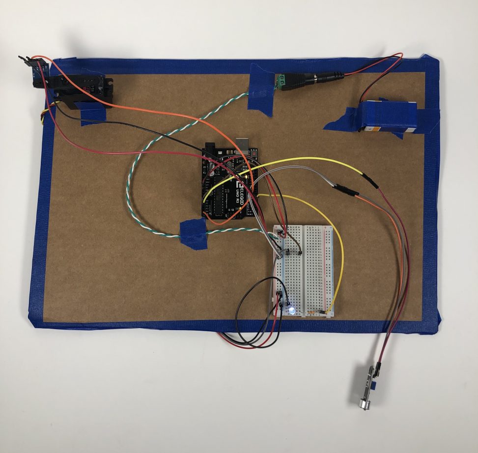
Our project in action
Detail Photos
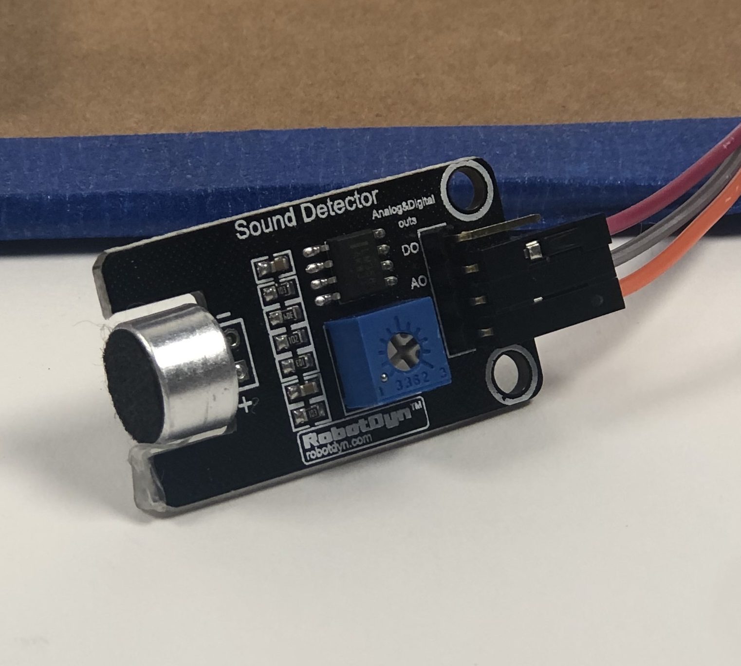
Microphone Piece
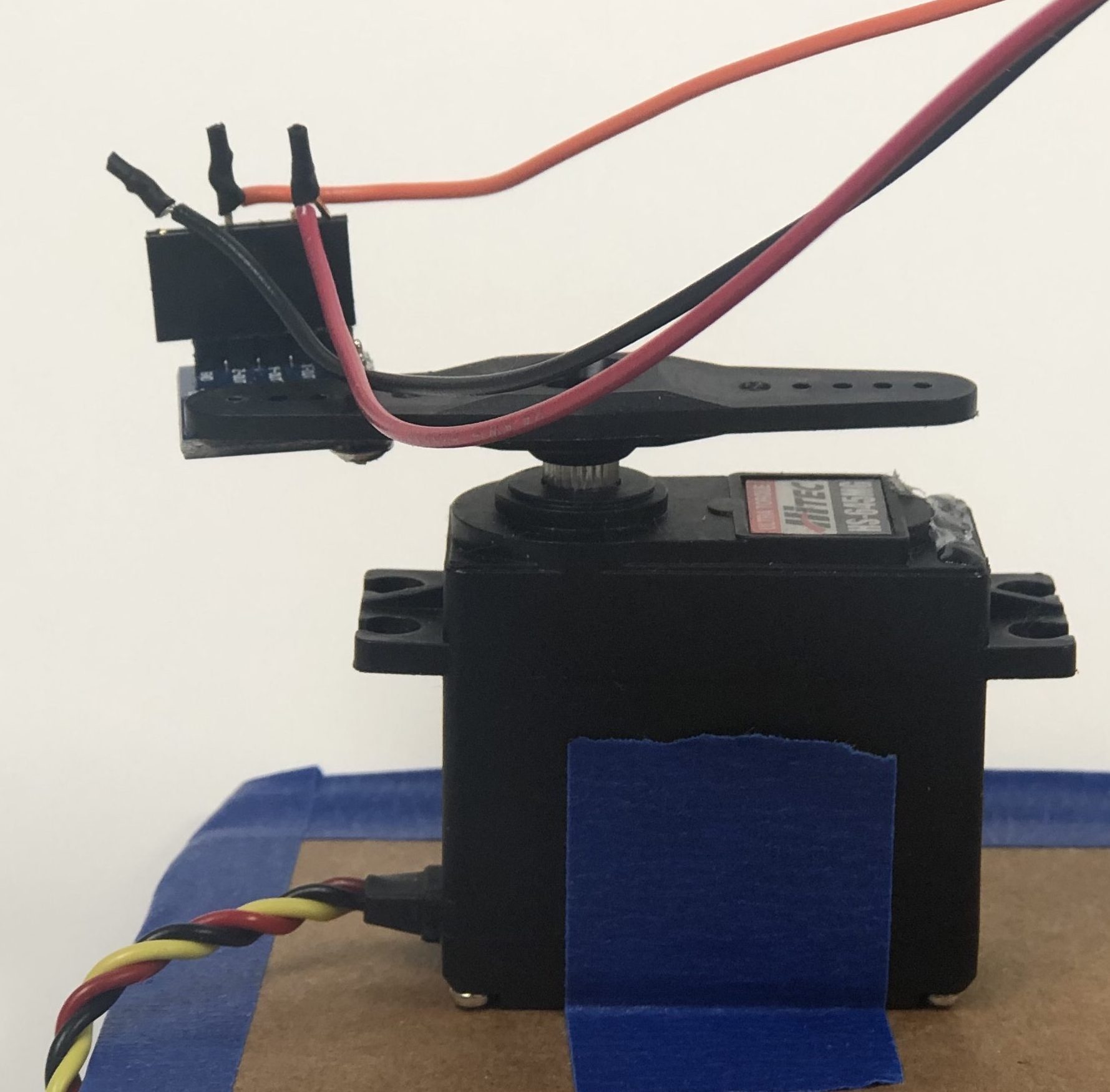
Motor and accelerometer
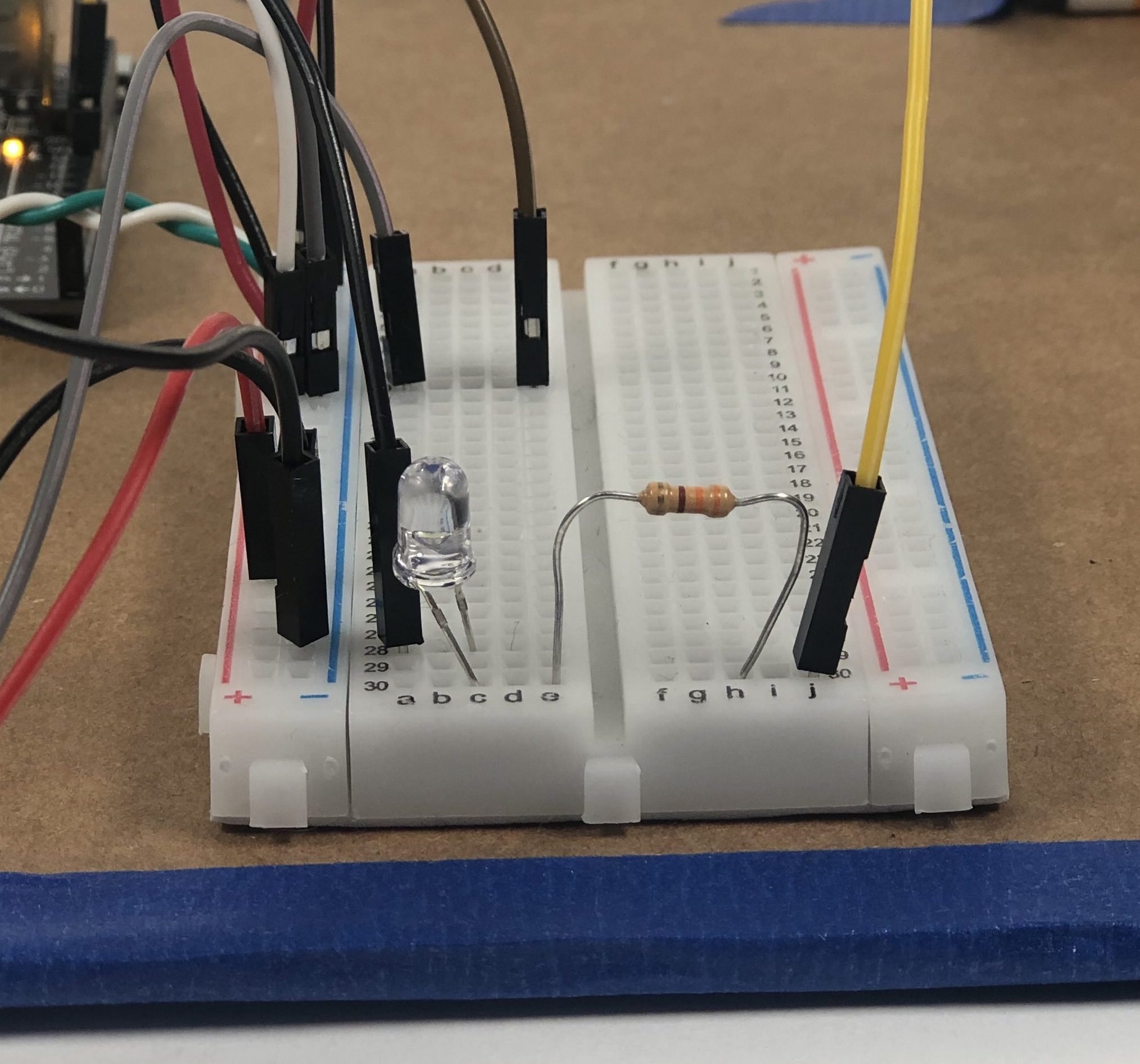
LED Light
Process Photos
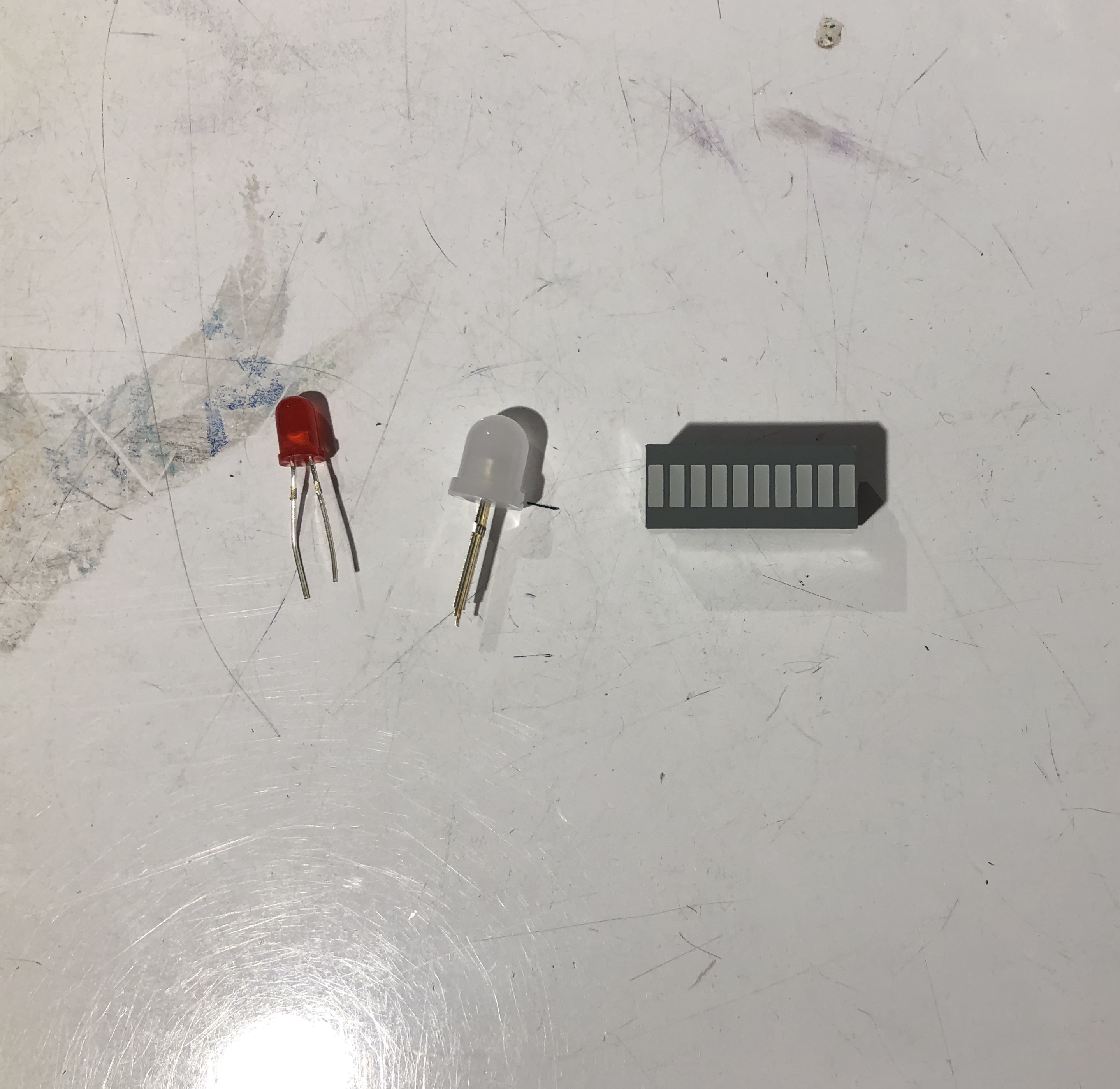
Potential LEDS
One of the earliest decisions we had to make was what LED to use to blink light. We liked the idea of using the LED with the bars in order to show different levels of input, but realized that it would be more difficult for the group whose input was light to detect the changes.
First Iteration of our project
In our initial iteration of this project, we stuck to simpler parts and worked with one input at a time. We used a smaller servo motor and taped a popsicle stick to the end, with the accelerometer taped on top of that to detect motion. We also used a basic 5V LED light. Once we got these smaller parts to work with our software, we changed some of the parts to refine the project. For example, we used a bigger servo motor to both create a greater range of motion and to reduce the noise interference with the sound input (the small servo motors are quite noisy!).
first iteration of project with popsicle stick motor arm
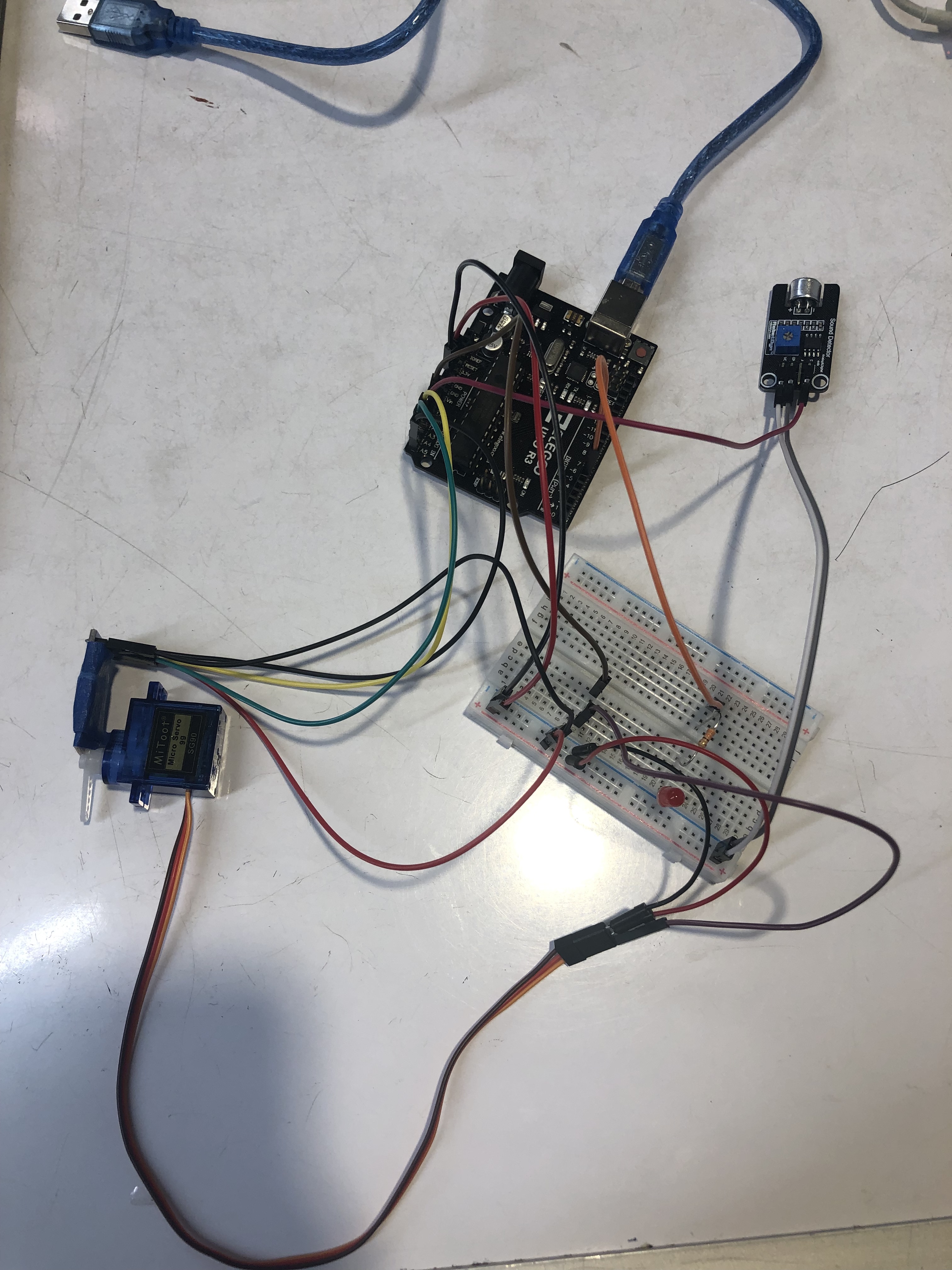
In our later iterations of this project, we added better and more secure wiring (not just using long streams of female-male parts) and mounted the parts to cardboard to make it more secure and standardized (which was important for detecting motion).
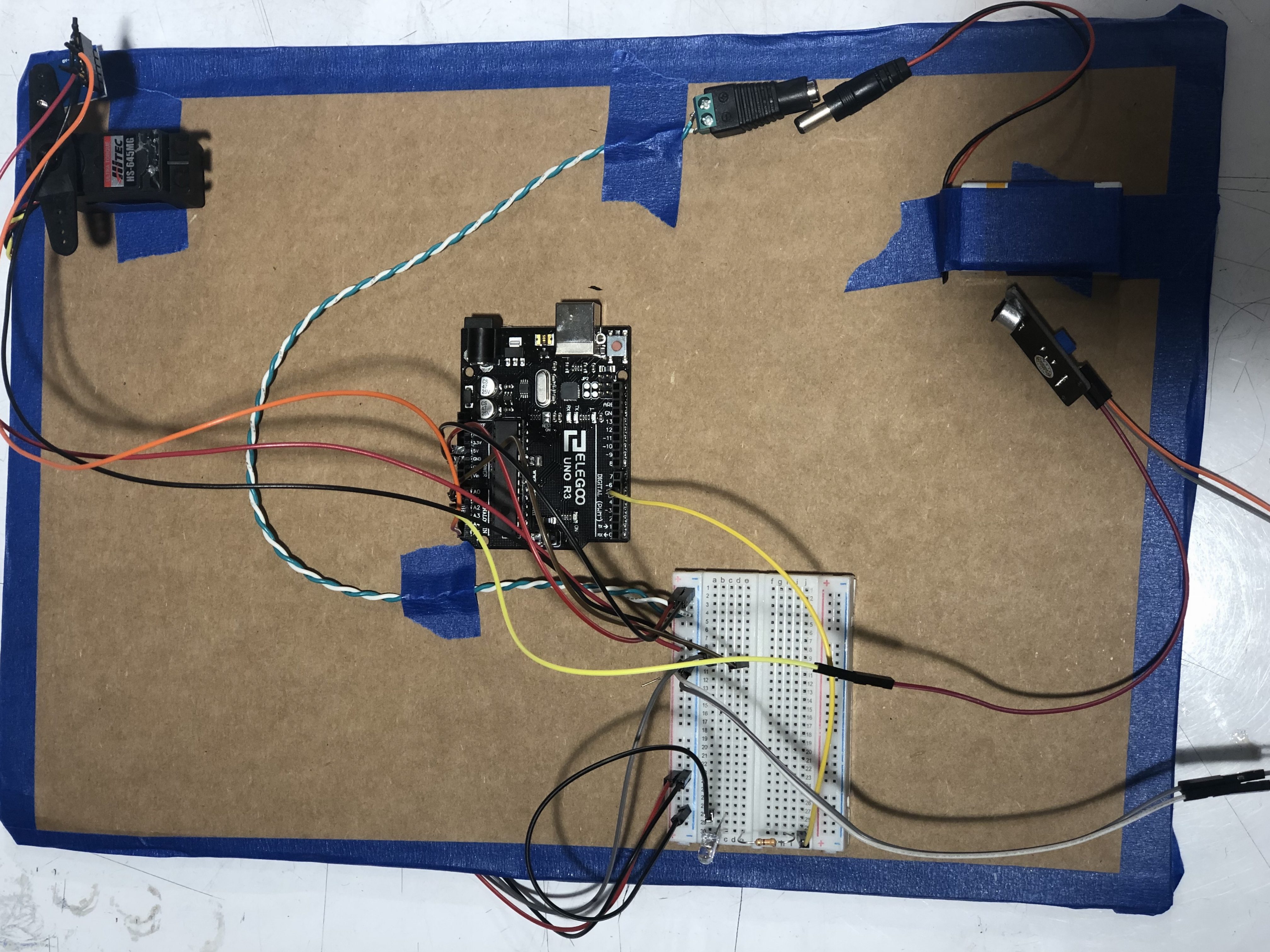
More refined iteration of our project
Discussion
Our initial approach was to start with the parts we knew and had learned about in the class and make sure they worked with the software we wrote before upgrading the parts to make the project more refined. We thought this approach was really helpful for us, and helped us to really perfect our software before having to fiddle with the hardware. For future projects, we think that this iterative, simplified approach will be a helpful guideline to follow.
One of the hardest parts of this project was defining the threshold for sound and motion. It was really difficult to test sound due to the noise of the rooms we were in, the noise coming from our parts, and due to the overall noisy nature of detecting analog input. We were able to find a good threshold only through multiple series of testing and iterating, in which we watched the serial plotter religiously and tried to identify peaks in the data points. We followed this same process for detecting motion with the accelerometer; we watched and used the data we saw on the serial plotter to inform our decisions for thresholds. We found that the data gained from the accelerometer was not at all what we expected as the largest peaks were shown through the z-axis. Rather than relying on our intuition, it was really important for us to rely on the empirical data we saw through testing, and to use that to write our code.
One of the easier parts of this project was implementing the light output, as we were familiar with the LED part and had used it for multiple previous projects. We considered using a neo-pixel diffused LED, which could take inputs and change color based on those inputs, but we found the library difficult to use and ultimately decided that, since the output was sound and not color, using the simple LED would suffice.
Because we stuck to the parts and signals that we were relatively familiar with, we may have limited ourselves in the project we were able to produce. While our project ultimately fulfilled the task handed to us, there may have been ways that we could have made our project “cooler” or more interesting had we gone more out of our comfort zones and experimented with new parts and signals. In the future projects for this class, we both hope to think more creatively and try new and wildly different things to create really interesting projects.
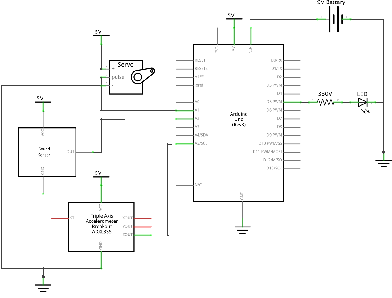
Schematic
Code
- <span class="com">// Double Transistor from Sound - Motion - Light</span><span class="pln">
- </span><span class="com">//</span><span class="pln">
- </span><span class="com">// Every half of a second, the program reads the input from a mic</span><span class="pln">
- </span><span class="com">// if the mic input is greater than a certain threshold (entered here as 725)</span><span class="pln">
- </span><span class="com">// it moves the servo motor</span><span class="pln">
- </span><span class="com">// within the loop the code is always checked the input from the accelerometer</span><span class="pln">
- </span><span class="com">// if the z-axis moves above a threshold, we turn on a LED light</span><span class="pln">
- </span><span class="com">//</span><span class="pln">
- </span><span class="com">//ARDUINO INPUTS</span><span class="pln">
- </span><span class="com">// A2 | MIC INPUT</span><span class="pln">
- </span><span class="com">// A3 | ACCELEROMETER INPUT</span><span class="pln">
- </span><span class="com">//</span><span class="pln">
- </span><span class="com">//ARDUINO OUTPUTS</span><span class="pln">
- </span><span class="com">// A1 | SERVO MOTOR</span><span class="pln">
- </span><span class="com">// 5 | LED LIGHT</span><span class="pln">
- </span><span class="com">#include</span><span class="pln"> </span><span class="str"><Servo.h></span><span class="pln">
- </span><span class="kwd">const</span><span class="pln"> </span><span class="kwd">int</span><span class="pln"> MIC_IN </span><span class="pun">=</span><span class="pln"> A2</span><span class="pun">;</span><span class="pln">
- </span><span class="kwd">const</span><span class="pln"> </span><span class="kwd">int</span><span class="pln"> SERVO_OUT </span><span class="pun">=</span><span class="pln"> A1</span><span class="pun">;</span><span class="pln">
- </span><span class="kwd">const</span><span class="pln"> </span><span class="kwd">int</span><span class="pln"> LED_IN </span><span class="pun">=</span><span class="pln"> </span><span class="lit">5</span><span class="pun">;</span><span class="pln">
- </span><span class="com">// For this device, we only read the Z PIN</span><span class="pln">
- </span><span class="kwd">const</span><span class="pln"> </span><span class="kwd">int</span><span class="pln"> ZPIN </span><span class="pun">=</span><span class="pln"> A5</span><span class="pun">;</span><span class="pln">
- </span><span class="kwd">int</span><span class="pln"> servoSwitch </span><span class="pun">=</span><span class="pln"> </span><span class="lit">0</span><span class="pun">;</span><span class="pln">
- </span><span class="typ">Servo</span><span class="pln"> servo</span><span class="pun">;</span><span class="pln">
- </span><span class="kwd">void</span><span class="pln"> setup</span><span class="pun">()</span><span class="pln"> </span><span class="pun">{</span><span class="pln">
- pinMode</span><span class="pun">(</span><span class="pln">MIC_IN</span><span class="pun">,</span><span class="pln"> INPUT</span><span class="pun">);</span><span class="pln">
- pinMode</span><span class="pun">(</span><span class="pln">LED_IN</span><span class="pun">,</span><span class="pln"> OUTPUT</span><span class="pun">);</span><span class="pln">
- pinMode</span><span class="pun">(</span><span class="pln">SERVO_OUT</span><span class="pun">,</span><span class="pln"> OUTPUT</span><span class="pun">);</span><span class="pln">
- pinMode</span><span class="pun">(</span><span class="pln">XPIN</span><span class="pun">,</span><span class="pln"> INPUT</span><span class="pun">);</span><span class="pln">
- pinMode</span><span class="pun">(</span><span class="pln">YPIN</span><span class="pun">,</span><span class="pln"> INPUT</span><span class="pun">);</span><span class="pln">
- pinMode</span><span class="pun">(</span><span class="pln">ZPIN</span><span class="pun">,</span><span class="pln"> INPUT</span><span class="pun">);</span><span class="pln">
- servo</span><span class="pun">.</span><span class="pln">attach</span><span class="pun">(</span><span class="pln">SERVO_OUT</span><span class="pun">);</span><span class="pln">
- </span><span class="pun">}</span><span class="pln">
- </span><span class="kwd">void</span><span class="pln"> loop</span><span class="pun">()</span><span class="pln"> </span><span class="pun">{</span><span class="pln">
- </span><span class="com">//check if z-axis of the accelerometer is above threshold</span><span class="pln">
- </span><span class="kwd">if</span><span class="pln"> </span><span class="pun">(</span><span class="pln">analogRead</span><span class="pun">(</span><span class="pln">ZPIN</span><span class="pun">)</span><span class="pln"> </span><span class="pun">></span><span class="pln"> </span><span class="lit">300</span><span class="pun">)</span><span class="pln"> </span><span class="pun">{</span><span class="pln">
- digitalWrite</span><span class="pun">(</span><span class="pln">LED_IN</span><span class="pun">,</span><span class="pln"> HIGH</span><span class="pun">);</span><span class="pln">
- </span><span class="pun">}</span><span class="pln">
- </span><span class="kwd">else</span><span class="pln"> </span><span class="pun">{</span><span class="pln">
- digitalWrite</span><span class="pun">(</span><span class="pln">LED_IN</span><span class="pun">,</span><span class="pln"> LOW</span><span class="pun">);</span><span class="pln">
- </span><span class="pun">}</span><span class="pln">
- </span><span class="com">//checking mic input for half a second every second</span><span class="pln">
- </span><span class="kwd">if</span><span class="pln"> </span><span class="pun">(</span><span class="pln">millis</span><span class="pun">()</span><span class="pln"> </span><span class="pun">%</span><span class="pln"> </span><span class="lit">1000</span><span class="pln"> </span><span class="pun"><</span><span class="pln"> </span><span class="lit">500</span><span class="pun">)</span><span class="pln"> </span><span class="pun">{</span><span class="pln">
- </span><span class="kwd">if</span><span class="pln"> </span><span class="pun">(</span><span class="pln">analogRead</span><span class="pun">(</span><span class="pln">MIC_IN</span><span class="pun">)</span><span class="pln"> </span><span class="pun">></span><span class="pln"> </span><span class="lit">725</span><span class="pun">)</span><span class="pln"> </span><span class="pun">{</span><span class="pln">
- servoMove</span><span class="pun">();</span><span class="pln">
- </span><span class="pun">}</span><span class="pln">
- </span><span class="pun">}</span><span class="pln">
- </span><span class="pun">}</span><span class="pln">
- </span><span class="com">//moves the servo back and forth once</span><span class="pln">
- </span><span class="kwd">void</span><span class="pln"> servoMove</span><span class="pun">()</span><span class="pln"> </span><span class="pun">{</span><span class="pln">
- </span><span class="kwd">if</span><span class="pln"> </span><span class="pun">(</span><span class="pln">servoSwitch</span><span class="pun">)</span><span class="pln"> </span><span class="pun">{</span><span class="pln">
- servo</span><span class="pun">.</span><span class="pln">write</span><span class="pun">(</span><span class="lit">5</span><span class="pun">);</span><span class="pln">
- servoSwitch </span><span class="pun">=</span><span class="pln"> </span><span class="lit">0</span><span class="pun">;</span><span class="pln">
- </span><span class="pun">}</span><span class="pln">
- </span><span class="kwd">else</span><span class="pln"> </span><span class="pun">{</span><span class="pln">
- servo</span><span class="pun">.</span><span class="pln">write</span><span class="pun">(</span><span class="lit">85</span><span class="pun">);</span><span class="pln">
- servoSwitch </span><span class="pun">=</span><span class="pln"> </span><span class="lit">1</span><span class="pun">;</span><span class="pln">
- </span><span class="pun">}</span><span class="pln">
- delay</span><span class="pun">(</span><span class="lit">100</span><span class="pun">);</span><span class="pln">
- </span><span class="pun">}</span>
Comments are closed.