With the goal of creating a useful implement for an older person in mind, we looked into the life of our team member Jeff. As a blinds installation professional, Jeff often has to demonstrate to his clients how his products affect the quality of light passing through them. We designed a portable and adjustable light source to help him simulate different lighting conditions in relation to his window blind samples.
Our initial meeting documentation can be found here.
Our prototype documentation can be found here.
What we built
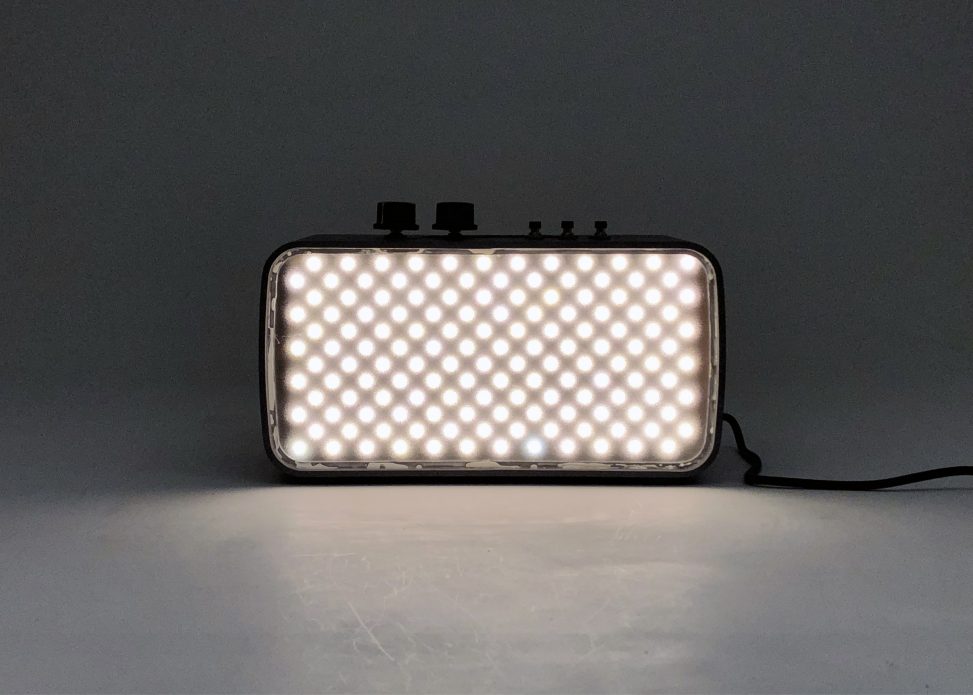
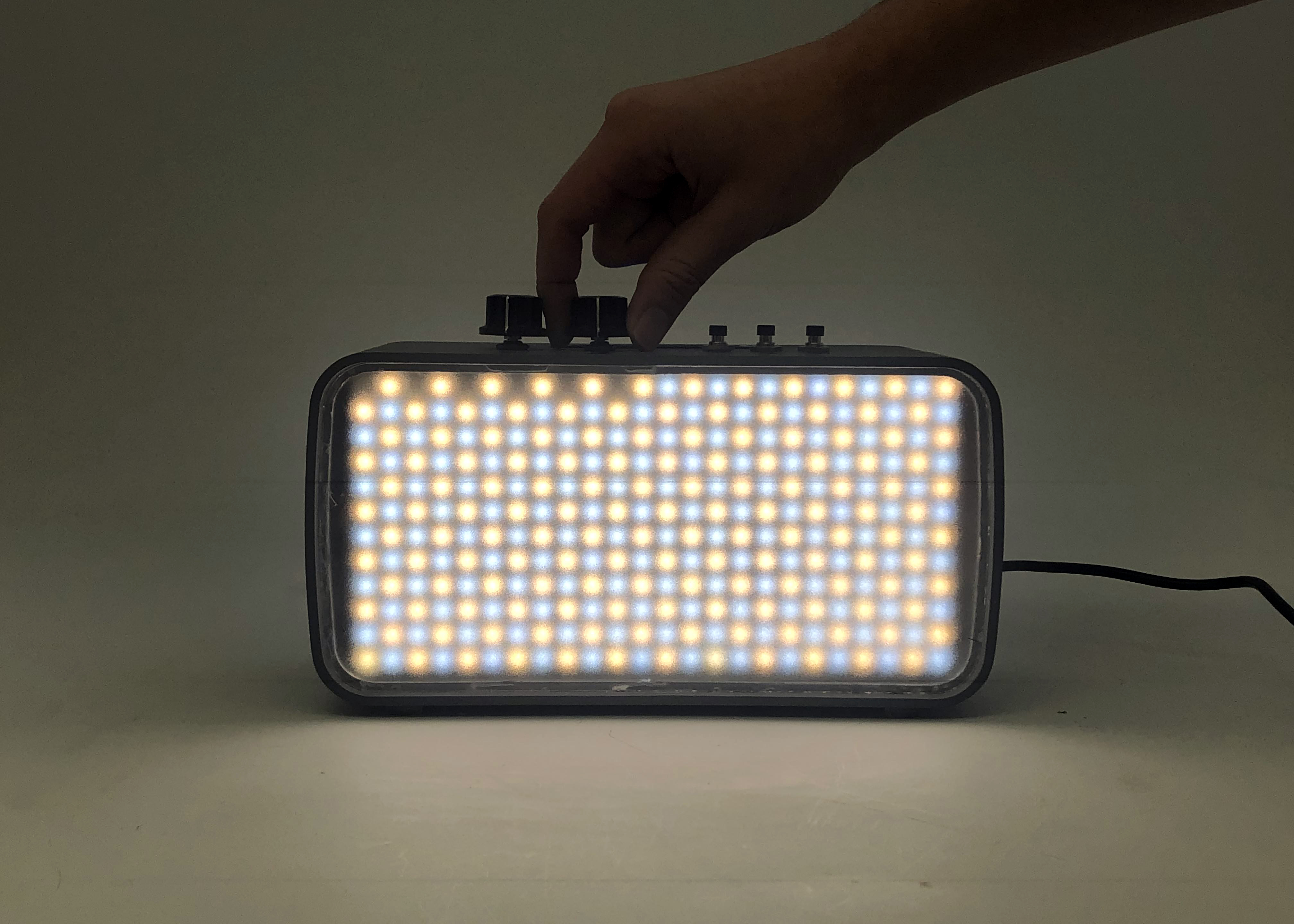
Our final product is a portable light source that replicates a range of weather and lighting conditions through a control panel on its top surface. Two knobs control color temperature and intensity, while three buttons provide sunny, cloudy, and sunrise/sunset lighting presets. These presets can also be customized by holding the button down for more than two seconds, adjusting the values, and pressing any button to save. Additionally, the light source comes with a carrier box that doubles as a stand. It can be used to transport the light source and adapter, and flipped over to act as a stand for the light source to be placed atop.
Overall Photo:
An overall image of the final product.
Basic Operation:
Demonstrating the knob and button interaction.
Details / Highlights:
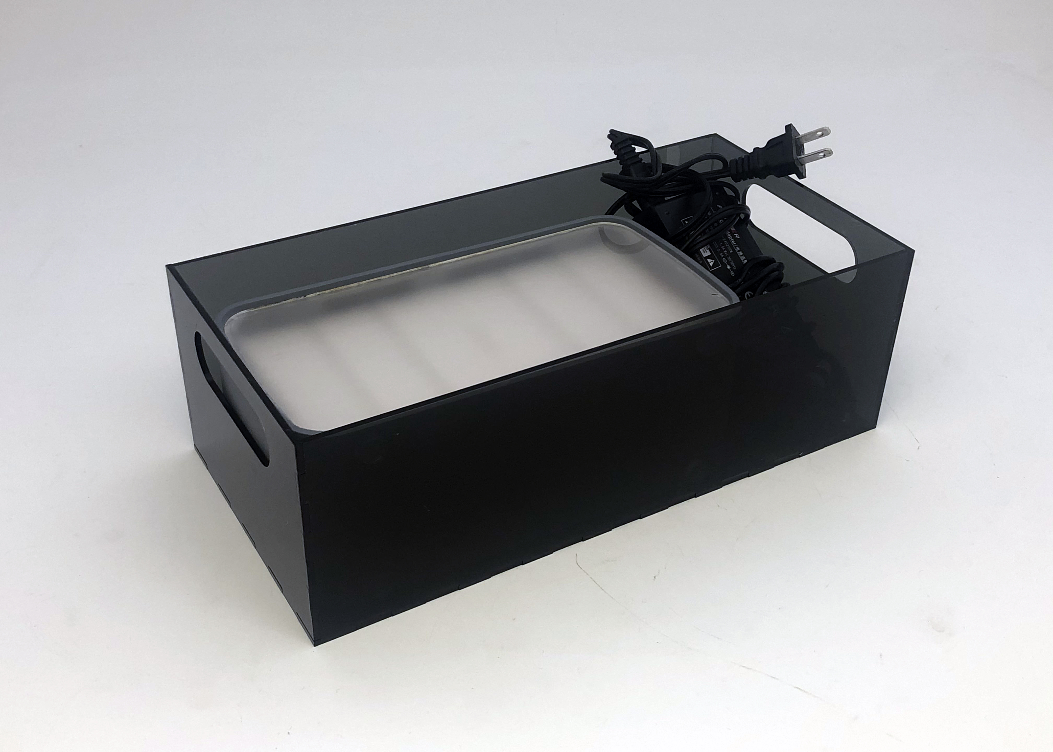
Light source and adapter in carrier.
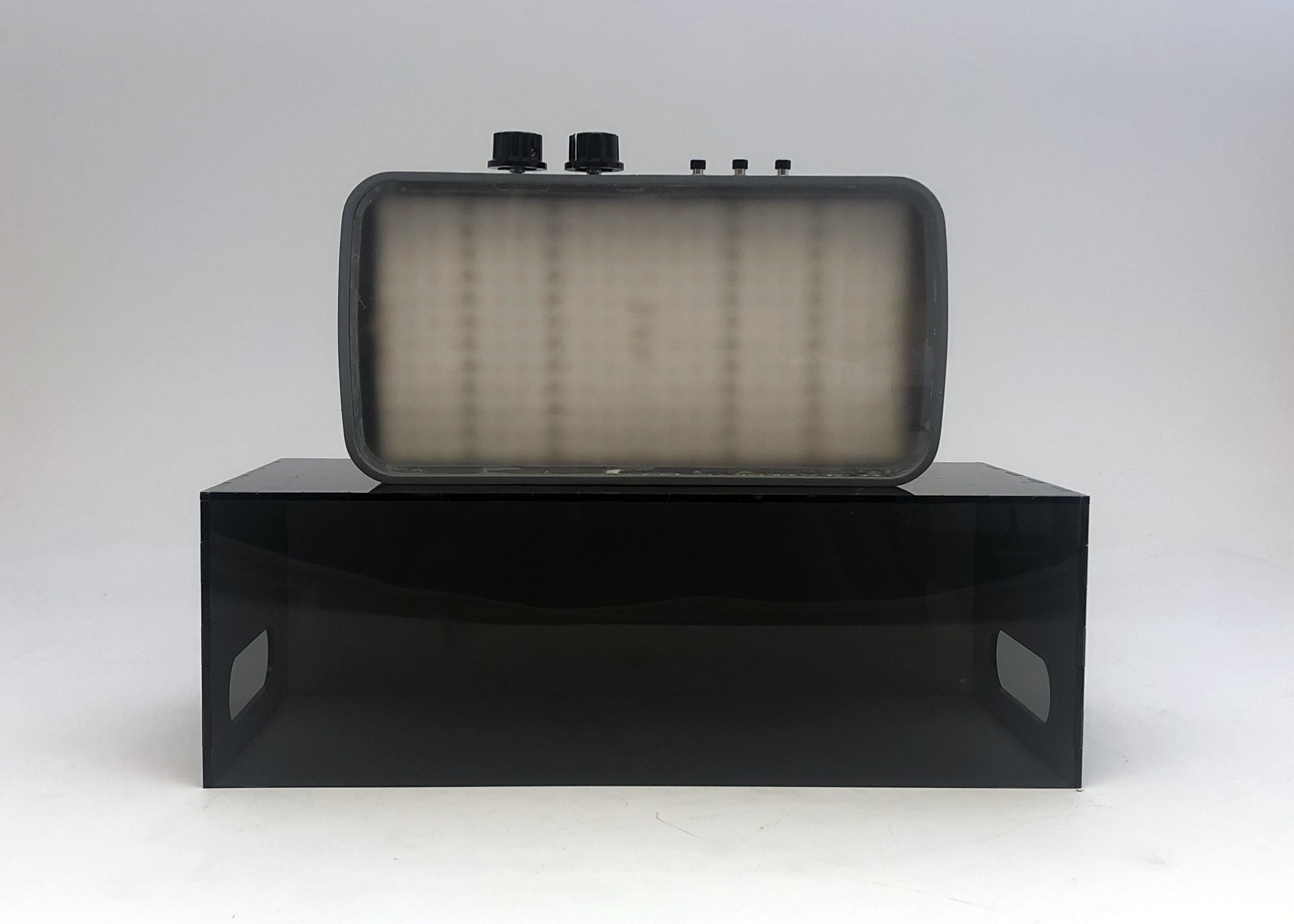
Light source (off) on stand.
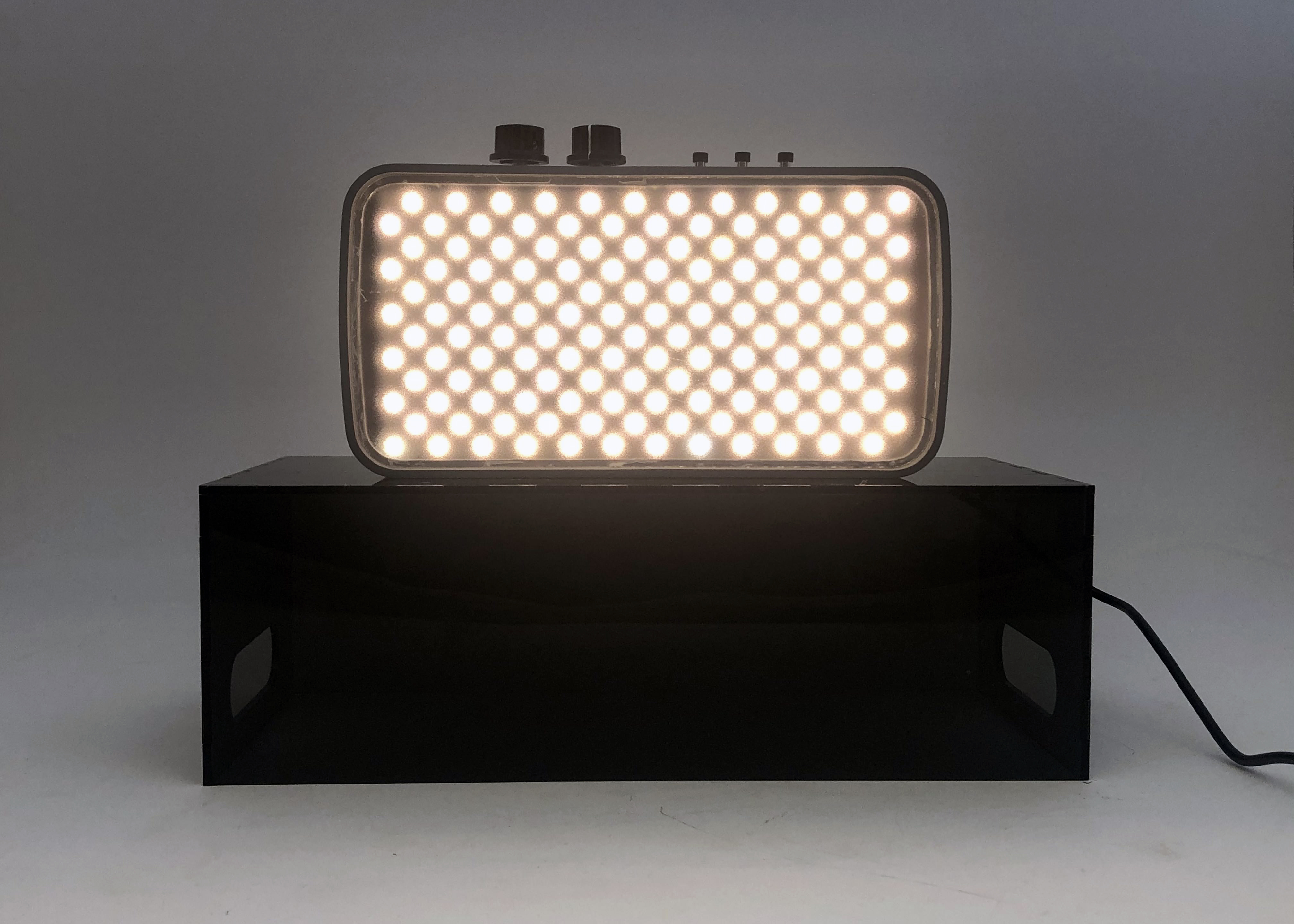
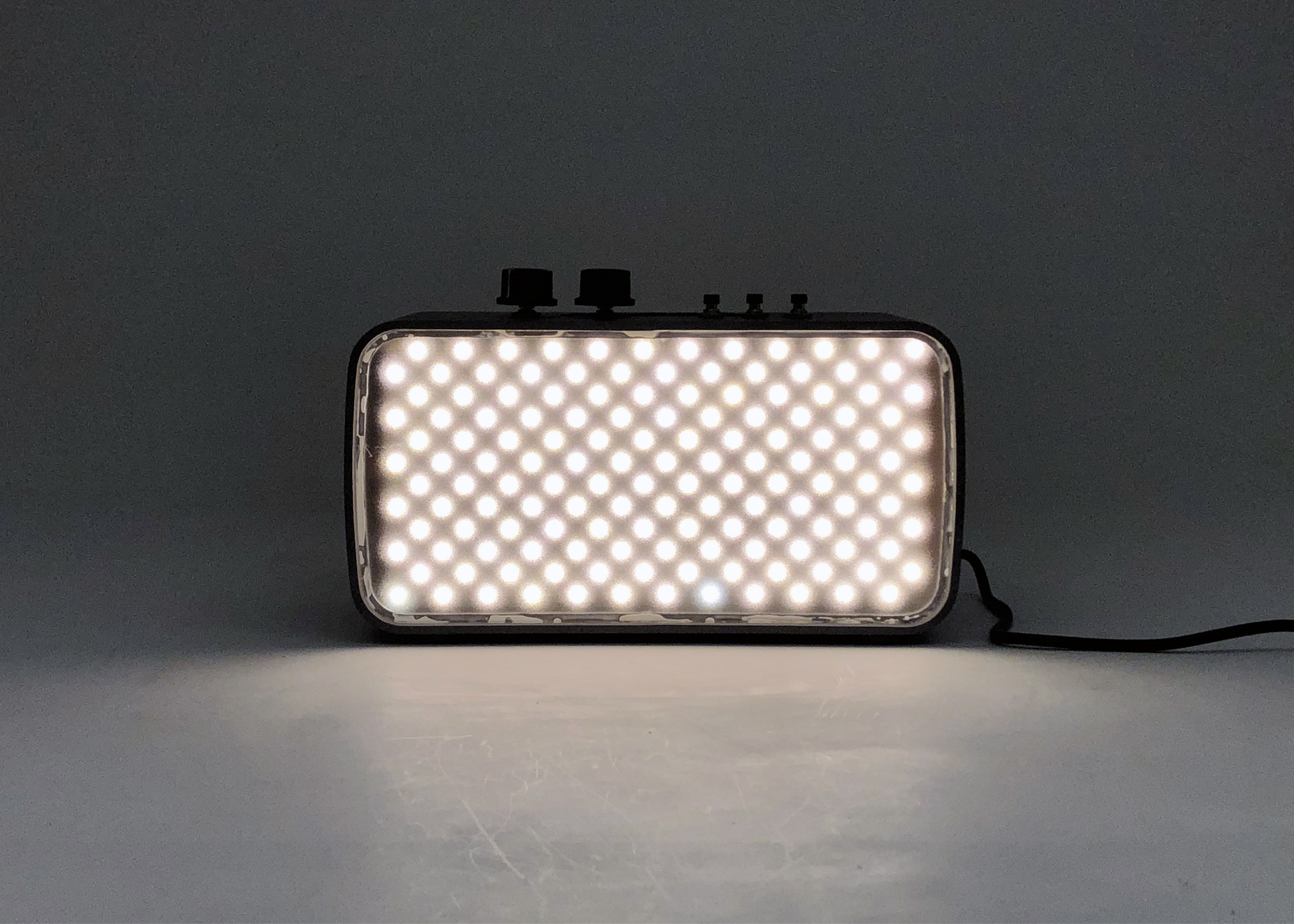
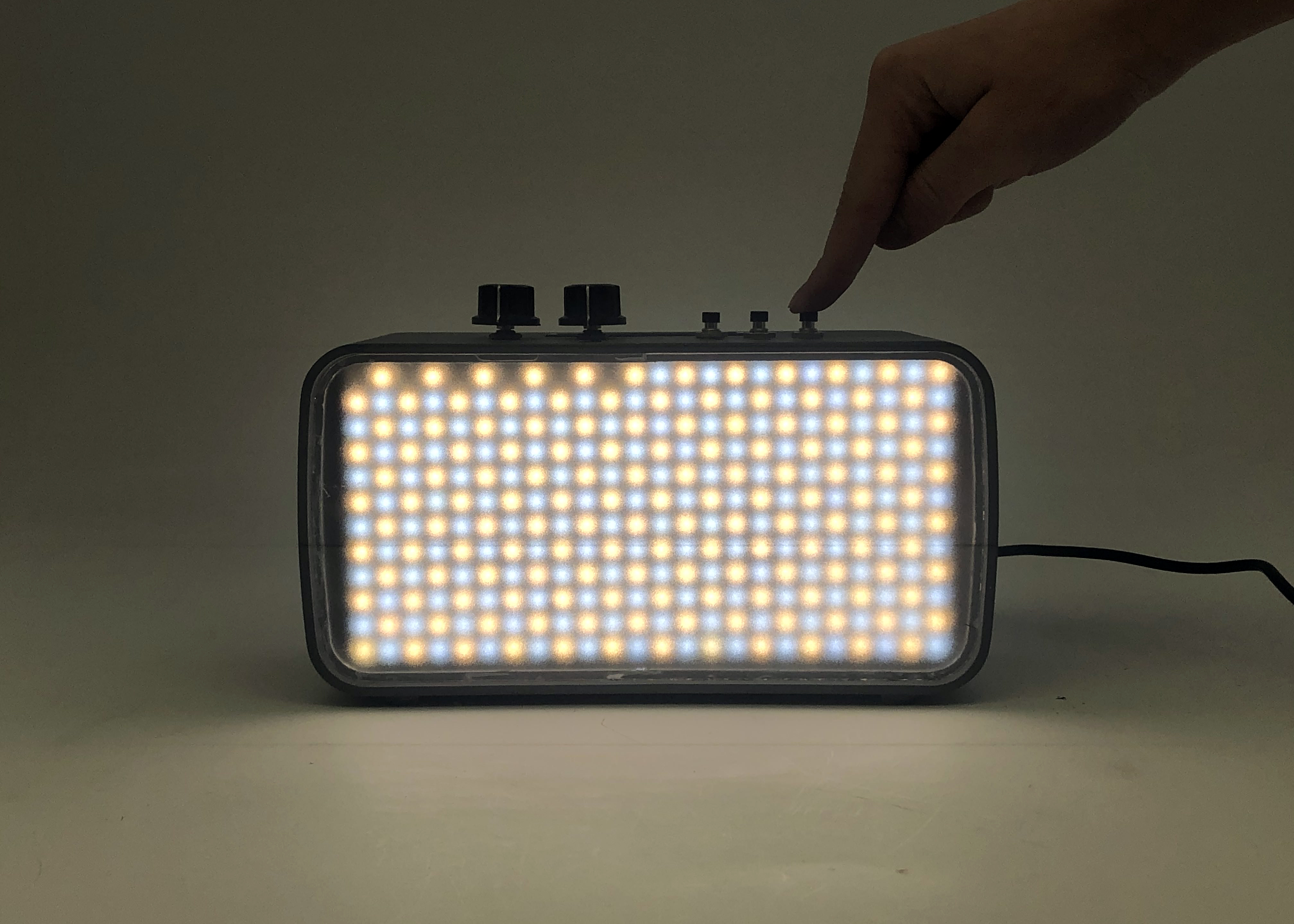
Light source (on) on stand.

Close-up of diffused LED panel.
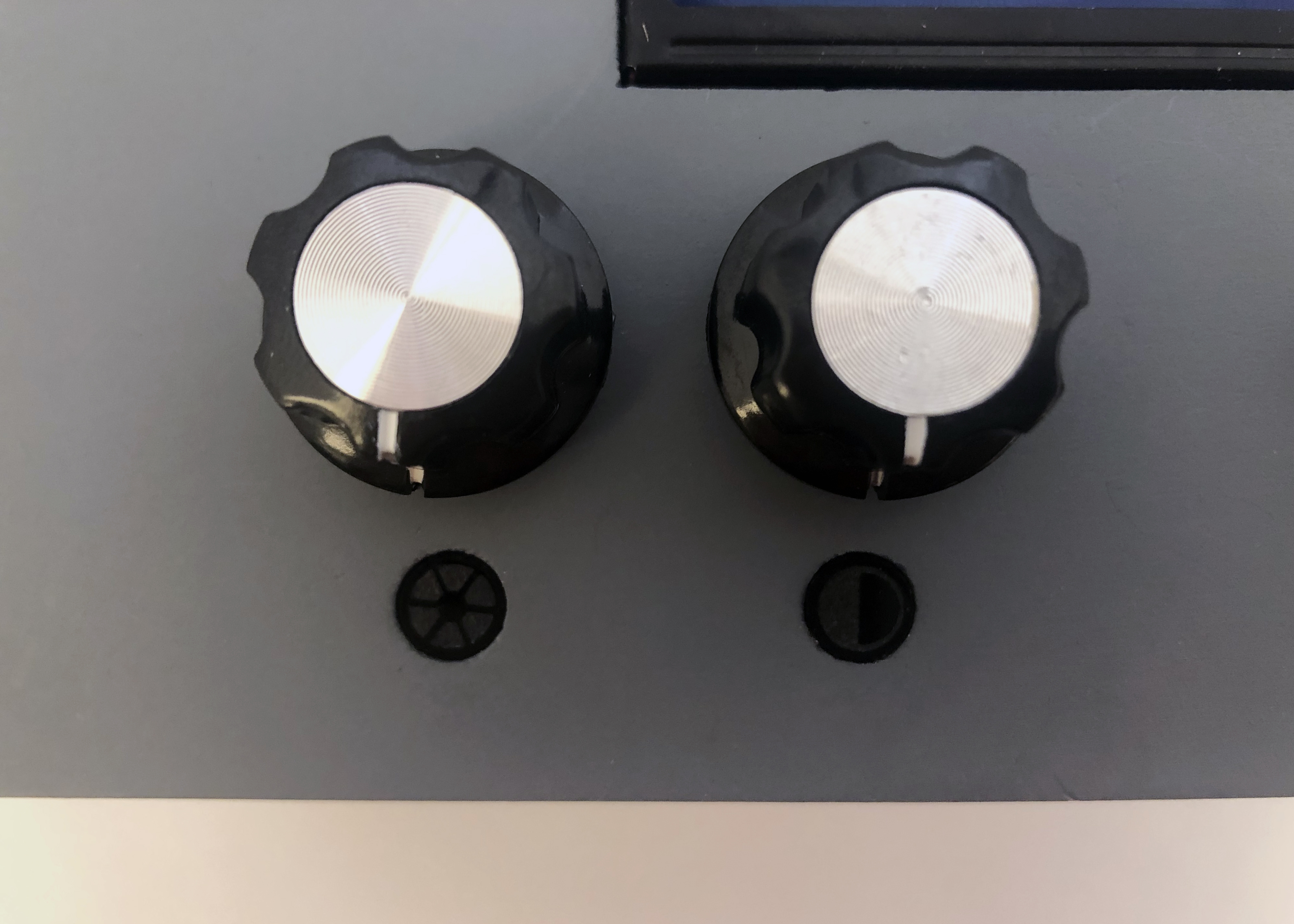
Knobs and their corresponding icons (left: color temperature, right: intensity).
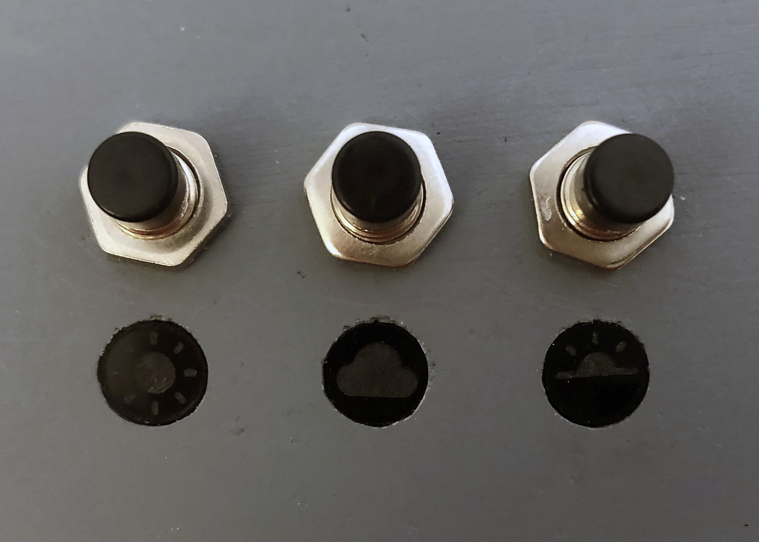
Buttons and their corresponding icons (left: sunny, middle: cloudy, right: sunrise/sunset).
Usage:
Turning the knobs.
Pressing the buttons.
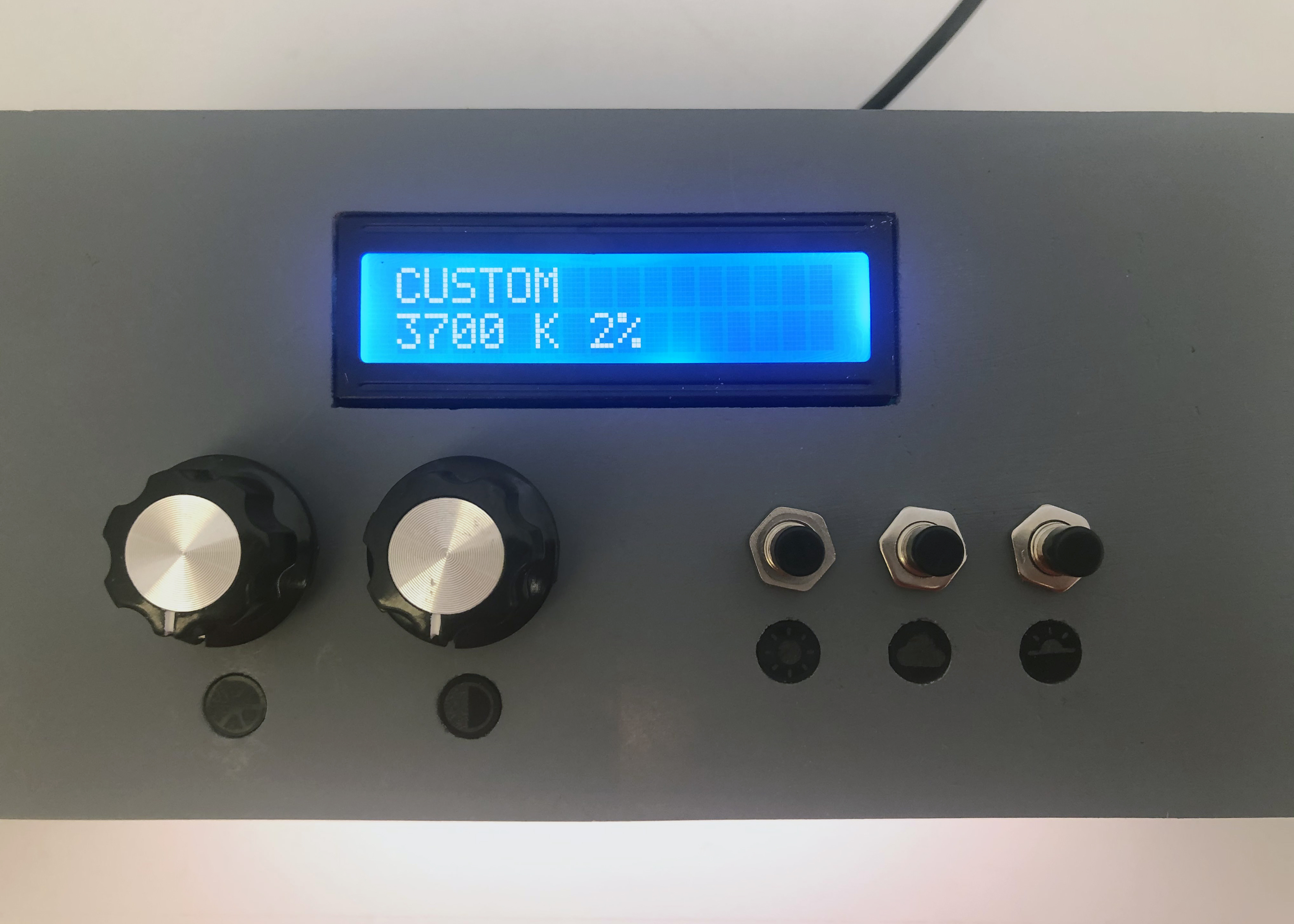
Reading the LCD display.
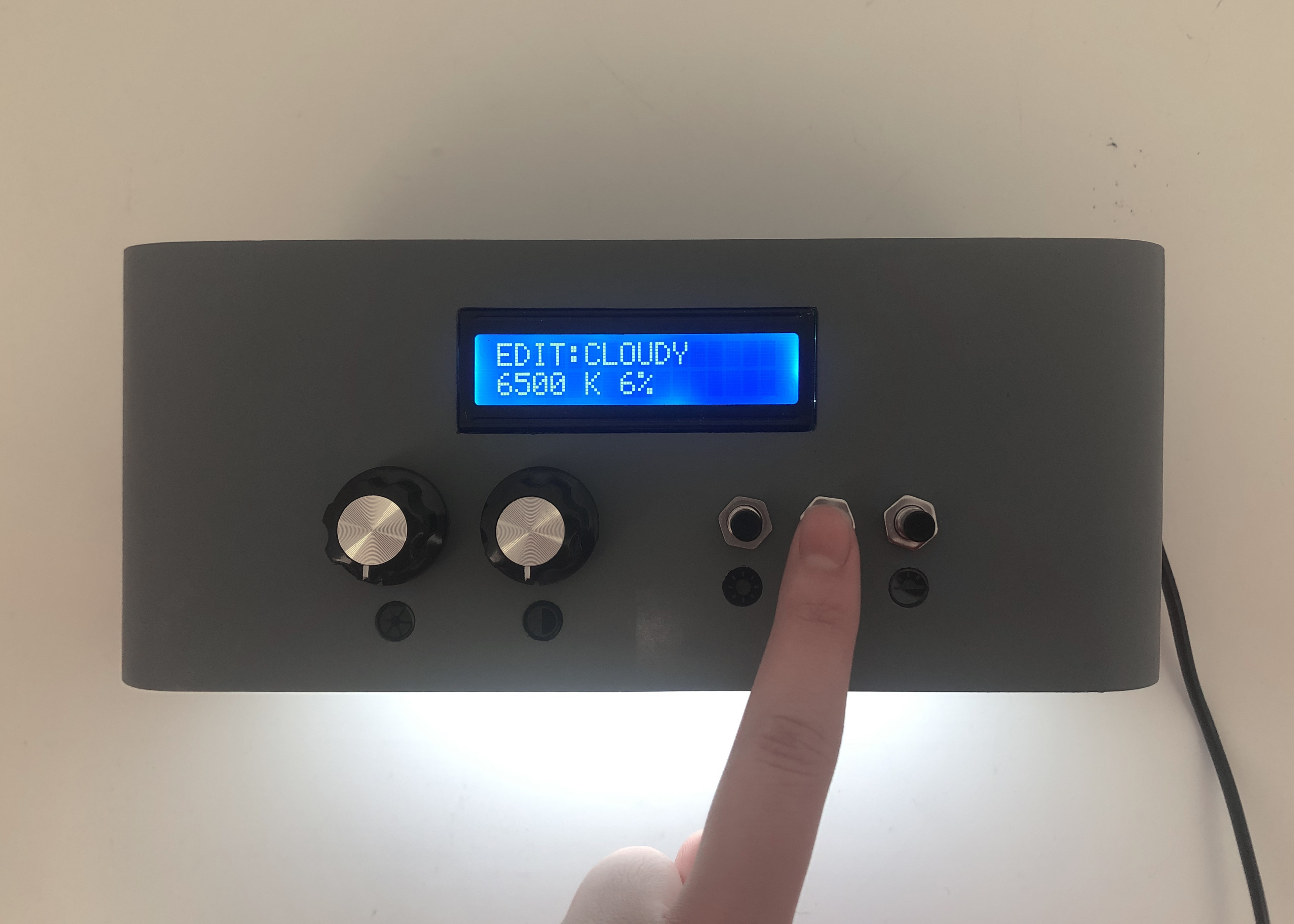
Editing the cloudy preset values.
Narrative:
Jeff has a sales pitch today at a client’s house. He places the lighting simulator and its adaptor into its carrier and packs it into his car. He commutes to his client’s house and brings the carrier inside along with his other equipment. As he is going through the window blind choices with his client, his client gets confused about some of the options. To give his client a better visual, Jeff unpacks the light and places it on top of its carrier. He plugs in the adaptor and the device turns on. He pressed the sunny button and holds the opaque blind sample in front to show that no light passes through. He then hold up the semi-opaque blind sample to show the difference in light quality. After Jeff fiddles with the light settings to give his client a realistic image of how light would pass through each of the blinds, Jeff’s client is able to make a confident decision on which blinds to purchase.
How We Got Here
In our initial planning, we split the tasks into three main stages: programming/hardware, fabrication, and assembly. Our proposed project timeline can be seen below:
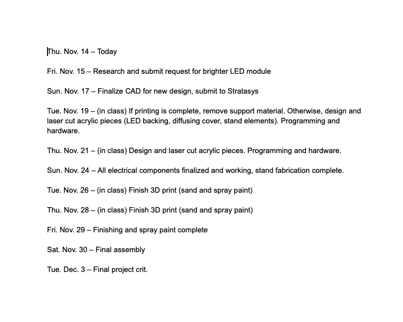
Proposed project timeline.
Based on the feedback we received on our prototype, we began by researching options for a brighter LED module in order to create a light source closer to natural sunlight.
After some research, we identified several important criteria we wanted our light source to achieve.
Since we intended to simulate lighting conditions through a window, the light source would have to achieve color qualities within a large portion of those ranges, which can extend from 1000 K to 10000K, which is basically a range from a deep red sunset to a deep blue sky. We determined that such a lighting simulator would be well-balanced if it encompassed the middle range, 3000K to 6000K, which would give options from orange-ish for dawn and dusk times to a white that’s tinted slightly blue for a general daylight color.
Secondly, we aimed for a product that could reproduce the intensities of sunlight and artificial lights to some degree. Sunlight intensity at Earth’s surface has a value of about 100,000 lux, and while a window is not likely to reach such intensities often, these can be important factors in replicating the performance of the blinds had they been demoed in those lighting conditions. Also, the high intensity also offers a way to simulate bright artificial lights, such as security lights, as well. Jeff mentioned that blinds may be installed with blocking such lights in mind, so a light capable of bright white light like that of bright sunlight could also approximate an artificial light to some extent.
A third factor that we thought was worth considering was the light source’s ability to simulate the quality of sunlight, specifically its full spectrum of light. A measure of a light’s quality, or closeness to the full spectrum, is its CRI value, so if we wanted a light that simulated lighting conditions, then it would make sense to have a light to approximate the natural light source as much as possible.
Thus, we settled on a light with the following specifications:
Color Range: 2700K – 6500K
Intensity: Max intensity is 3500 lumens at a color temperature of 4100K (close to white). A quick calculation gives around 110,000 to 120,000 lux. This is of course at its peak intensity, which occurs at a color temperature of 4100 K, but this intensity is mostly just necessary for direct sunlight, which is a close temperature of around 5000K, so the light should still be able to get close to the necessary intensity.
CRI value: rated to at least 95 CRI on a scale of 100.
Overall, the LED strip we got generally satisfied all our criteria. The only catch was that they were rather expensive. A link to the store page is provided below.
BC Series High CRI LED Multirow Hybrid Color Temperature LED Flexible Strip – Pack: 1 pcs
Fabrication Details
In terms of fabrication, the first step was to make adjustments to the design of the outer casing. Jeff had requested that the form be elongated horizontally to cover more area. In addition, he asked for a stand to elevate the light in order to create extra space at the bottom for when he stretches the blind sample. The outer casing and stand were designed in tandem to fit together. With the element of the light, adaptor, and stand in mind, we decided to make the stand double as a carrying case that can transport the other two items. We thought this could be particularly useful for Jeff since he commutes to his clients’ homes by car.
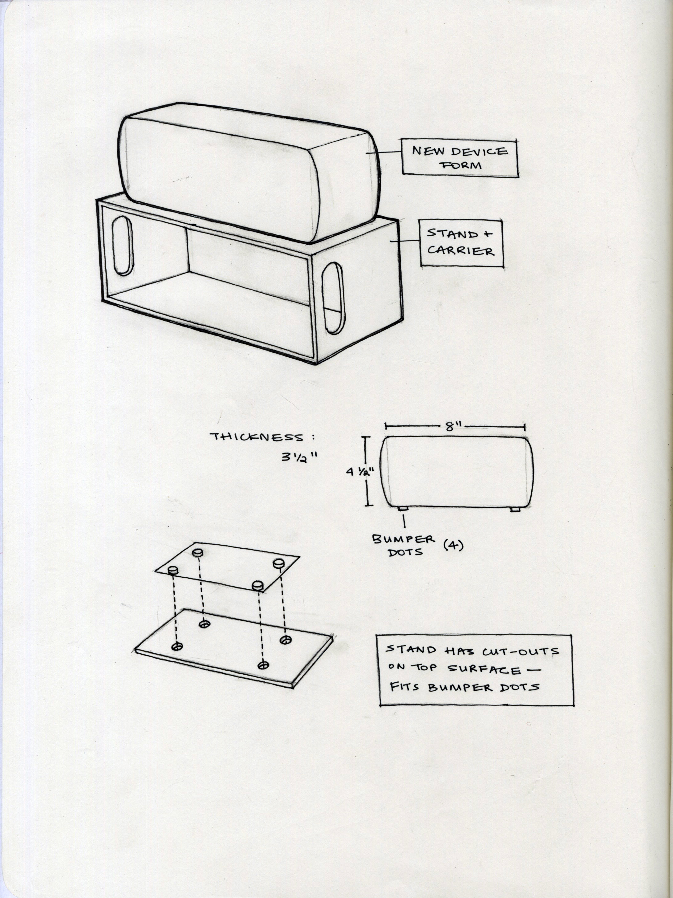
Redesigning aspects through sketching. Jeff had also mentioned that the light should be stable atop the stand, so we decided to add bumpers to the bottom face of the light that perfectly fit into cutouts on the top face of the stand.
After the designs were finalized, we constructed the CAD model for the outer casing in Fusion360 and sent it for 3D printing through the Stratasys printer.
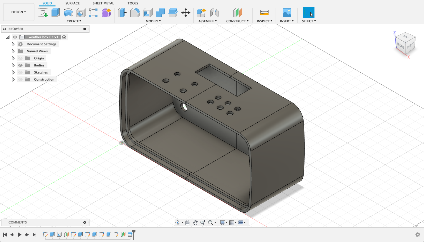
Screenshot of the outer casing CAD model in Fusion 360.
We based the dimensions of the stand on the size of both the light and its adaptor. We input these dimensions into makeabox.io which gave us the dxf file to laser cut the stand. Slots on either side were added in Adobe Illustrator for when Jeff chooses to use the stand as a carrying case. We also added the circle cutouts that would fit the bumpers. Beyond this, fabricating the stand was a fast process.
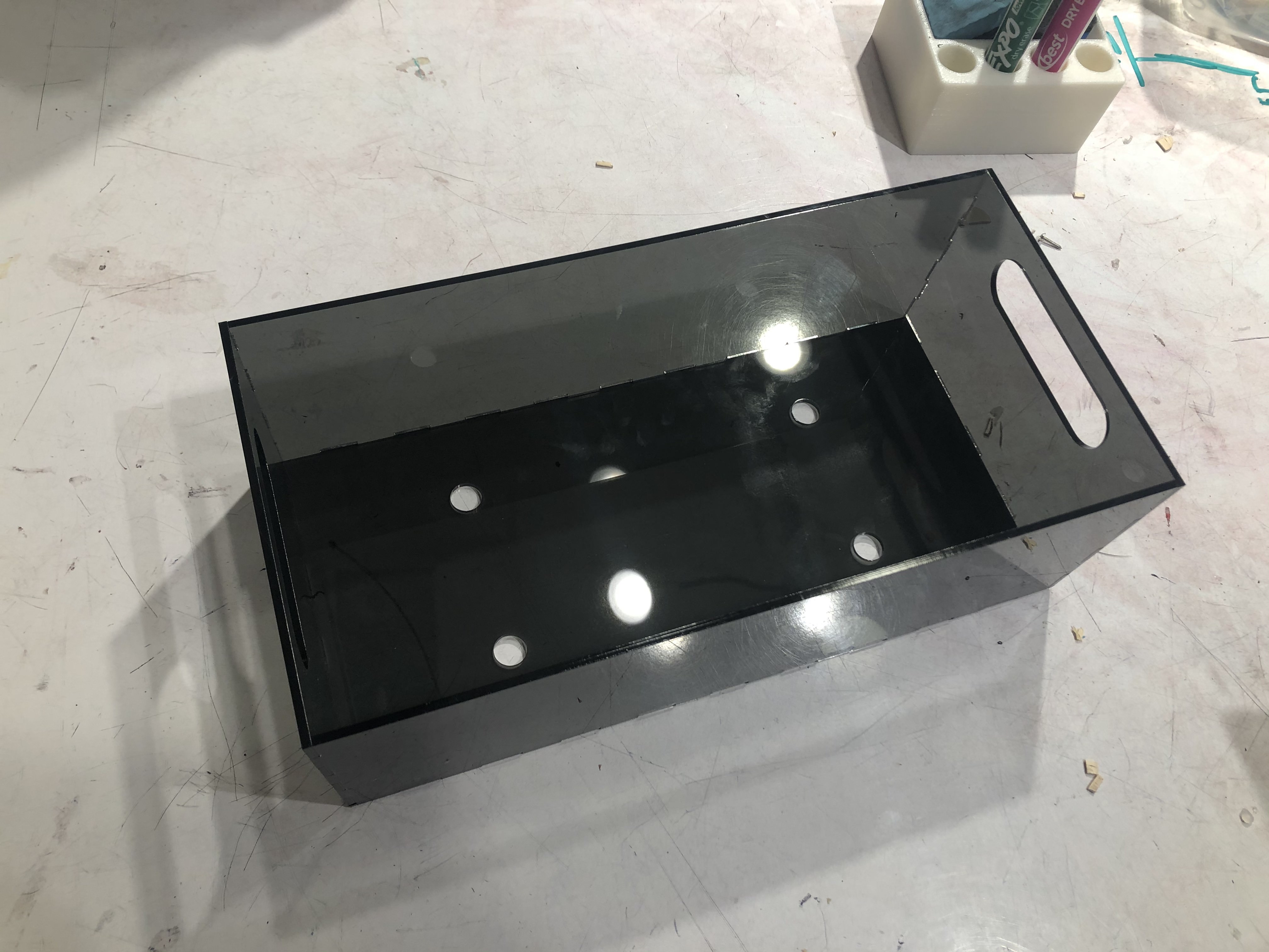
The finished stand / carrier. The laser cut pieces were then joined together using bondene.
As for the outer casing, the 3D print was placed in the parts wash and finished using bondo and spray paint. Bondo was applied and sanded down to create a smooth surface for spray painting. We chose to use matte grey spray paint because Jeff wanted a sleeker look.
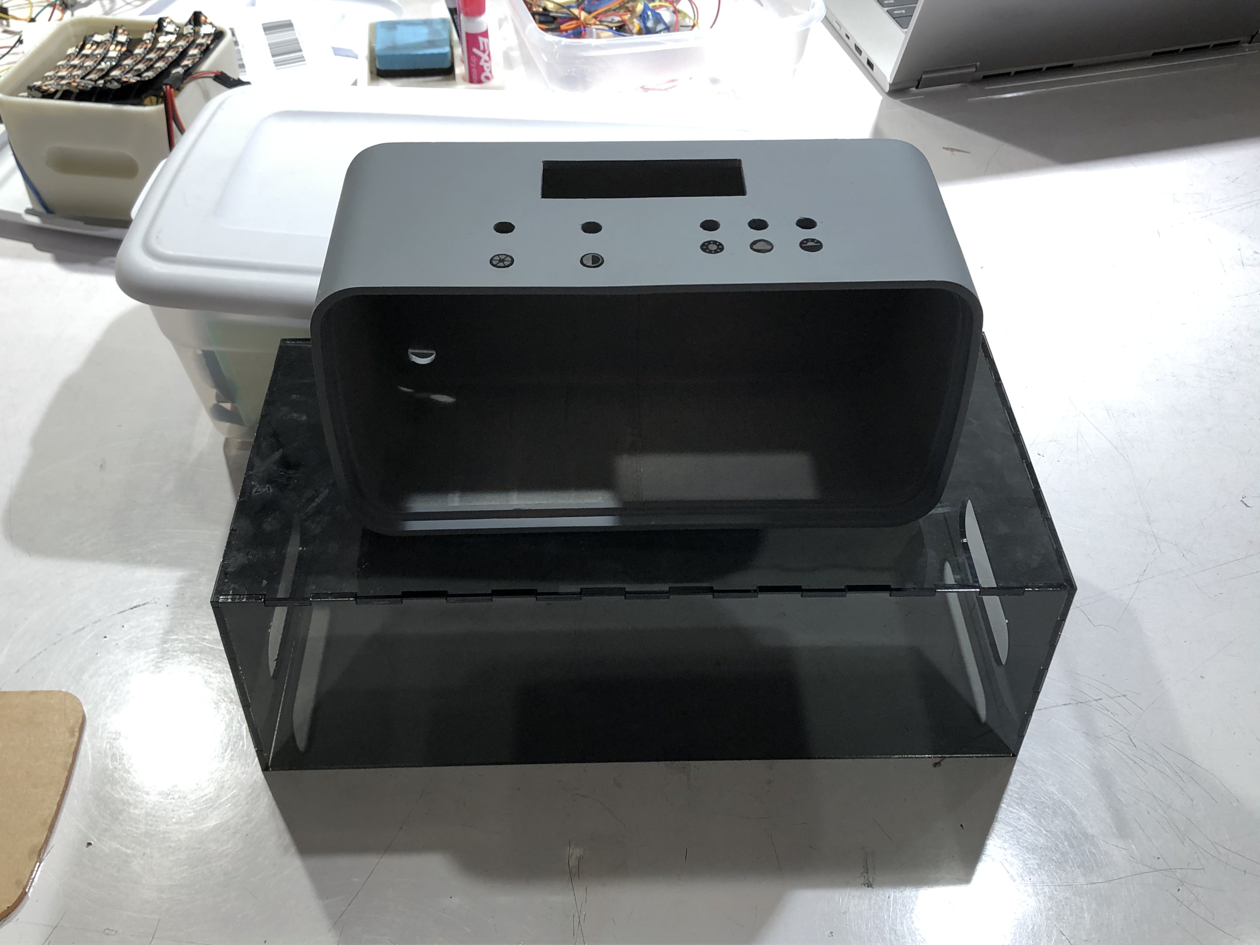
The finished stand / carrier and outer casing. Icons can be seen beneath the hole for each knob / button.
We also laser cut and engraved small icons that indicate the function of each knob / button. From left to right, the icons represent the color temperature knob, the brightness / intensity knob, the sunny preset button, cloudy preset button, and sunrise / sunset preset button. The holes for the icons were designed into the CAD file.
Finally, we added the bumpers on the bottom face of the outer casing.
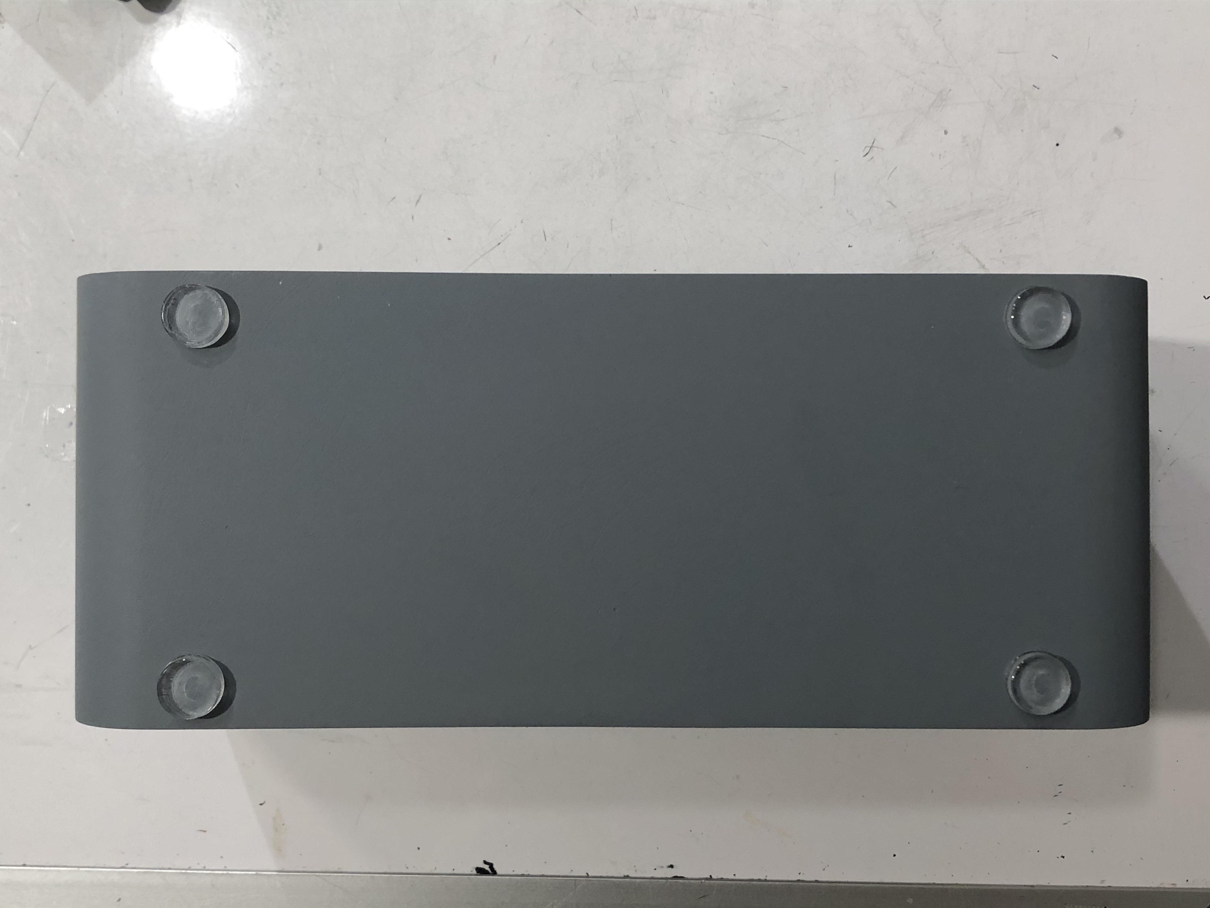
Bottom face of outer casing with bumpers attached.
Technical details
While the structure of the prototype code was largely retained by the final code, several revisions had to be made account for several factors.
The initial big change was switching from using a LED library to manage the LEDs to a more ‘manual’ direct control of the LED intensities via PWM on transistors that controlled the actual current flow to the LED panels, although this is greatly simplified by the analogWrite() function.
This also meant that the color temperature of the board would have to be guided through a completely different method. The research on the LEDs here offered some helpful information on how the colors blended between the two LED circuits on the board, one for warm LEDs and one for cold LEDs, to produce the color temperatures we desired. One of the graphs on the sight indicated a close to linear relationship between intensity and color for both LED circuits given the other one was fully on, so I reasoned that the intensity of either circuit would cause an additive change in the temperature given the other was fully on. Without a way to test, we couldn’t be entirely sure, but the visual results suggested that the observed LED color temperatures were fairly close to the color temperatures we mapped them to.
Another change that was included fairly late in the game was the inclusion of a save system for the button presets, which resulted in some less than optimal code since it hadn’t been initially planned for.
On the electronics side of things, there were several notable changes to account for the high voltage LED panels and their 2 circuit design. We switched to using transistors and power regulators in the design to account for the 24V supply we switched to per the voltage requirements of the LEDs while allowing us to power the 5V Arduino Pro Mini. As pushing current through a resistor wastes a lot of the power that the LED will use and creates heating problems, a transistor allowed us to control the LED intensity as well in conjunction with PWM.
Before fully committing to the new design, we tested a few subsystems like transistors and power regulators on a solderless breadboard with the LED panel before upgrading to a soldered one for a more permanent design. This soldering requirement forced us to switch to the Arduino Pro Mini as we had been using the Arduino Uno for the prototype and testing many of the subsystems.
Soldering ended up taking a fair deal of time, but once it was done, all that was left was to install the wired up parts into the frame. We did not solder the power supply barrel jack immediately to the board however as we needed to mount it first, so we soldered the rest of the board before mounting the barrel jack, then soldered the barrel jack’s wires to the board.
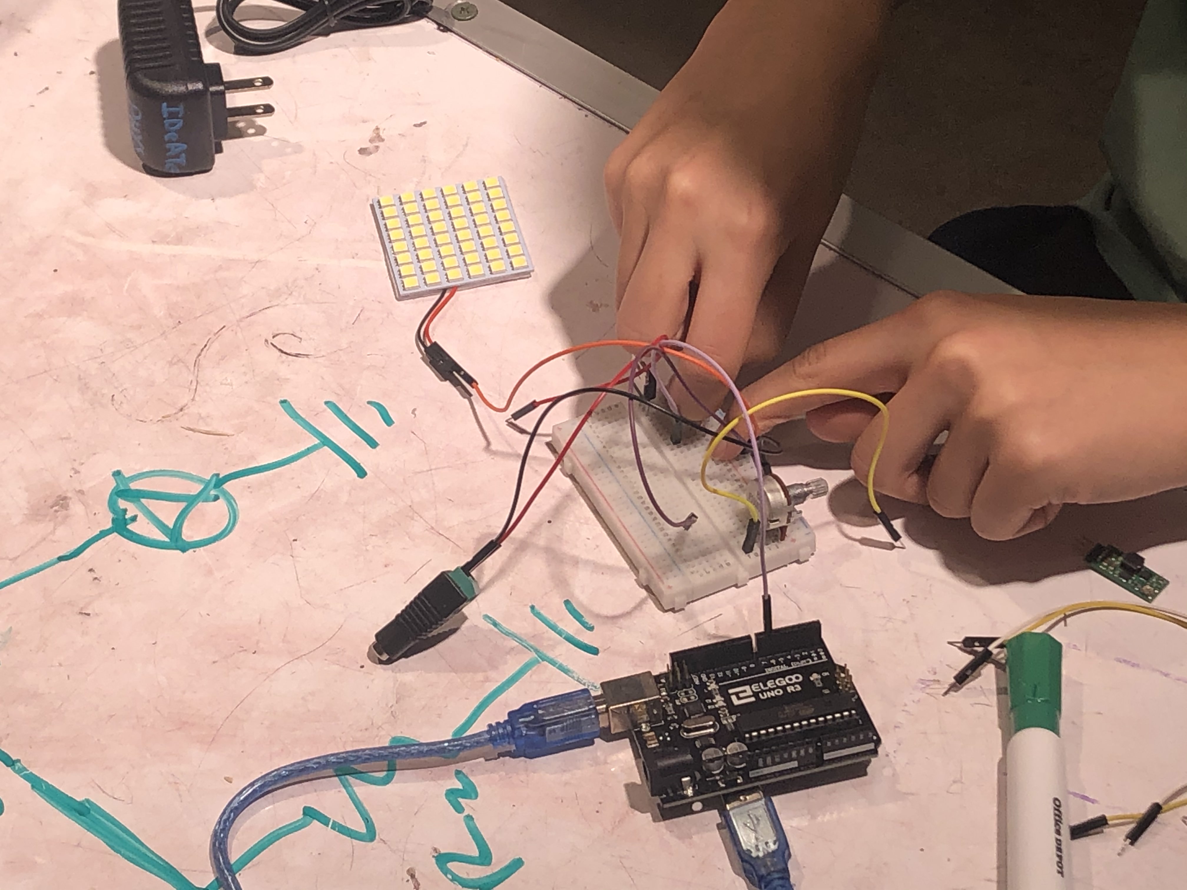
Testing the code and electrical components on a mini LED panel before our actual module arrived in the mail.
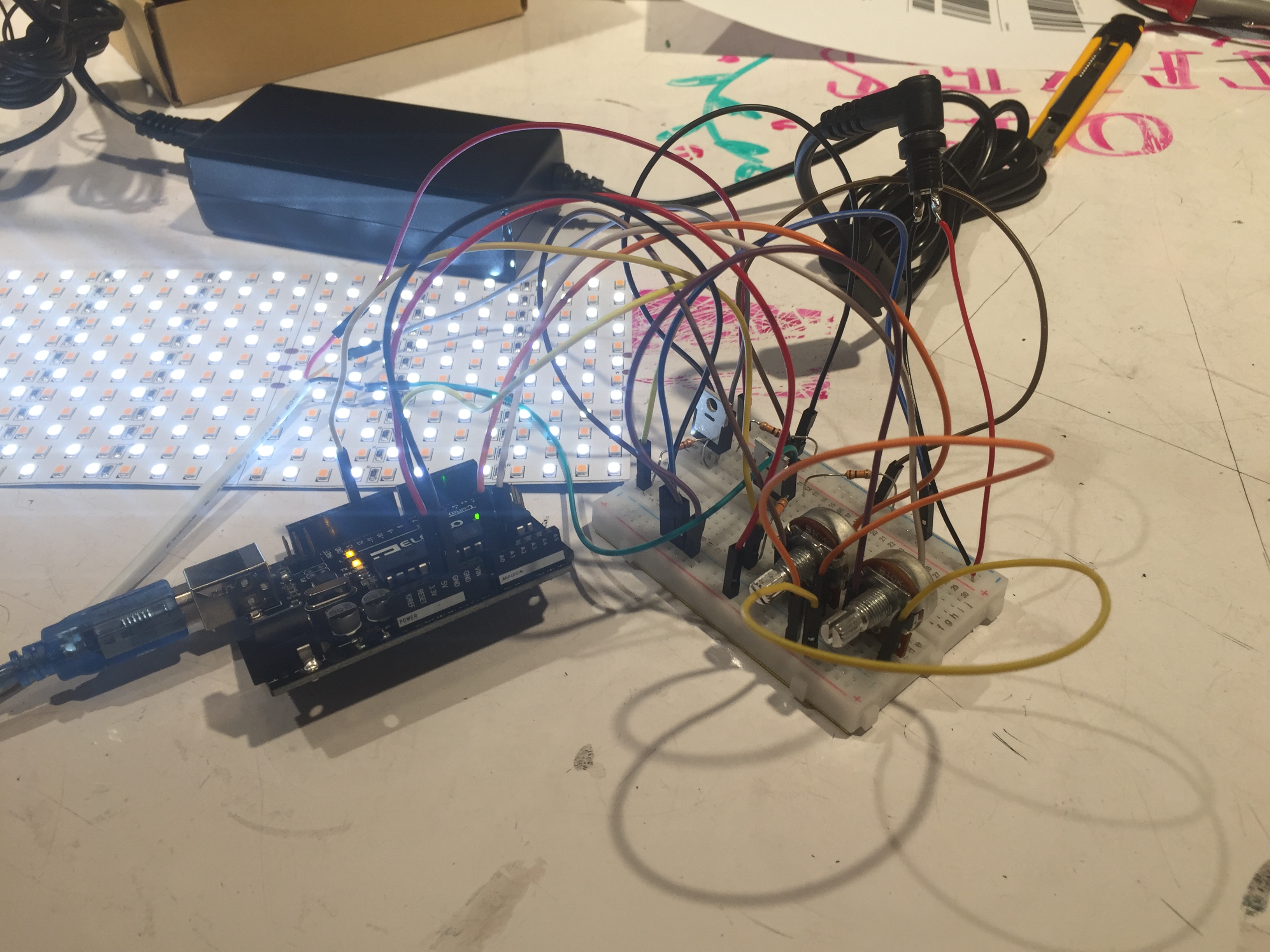
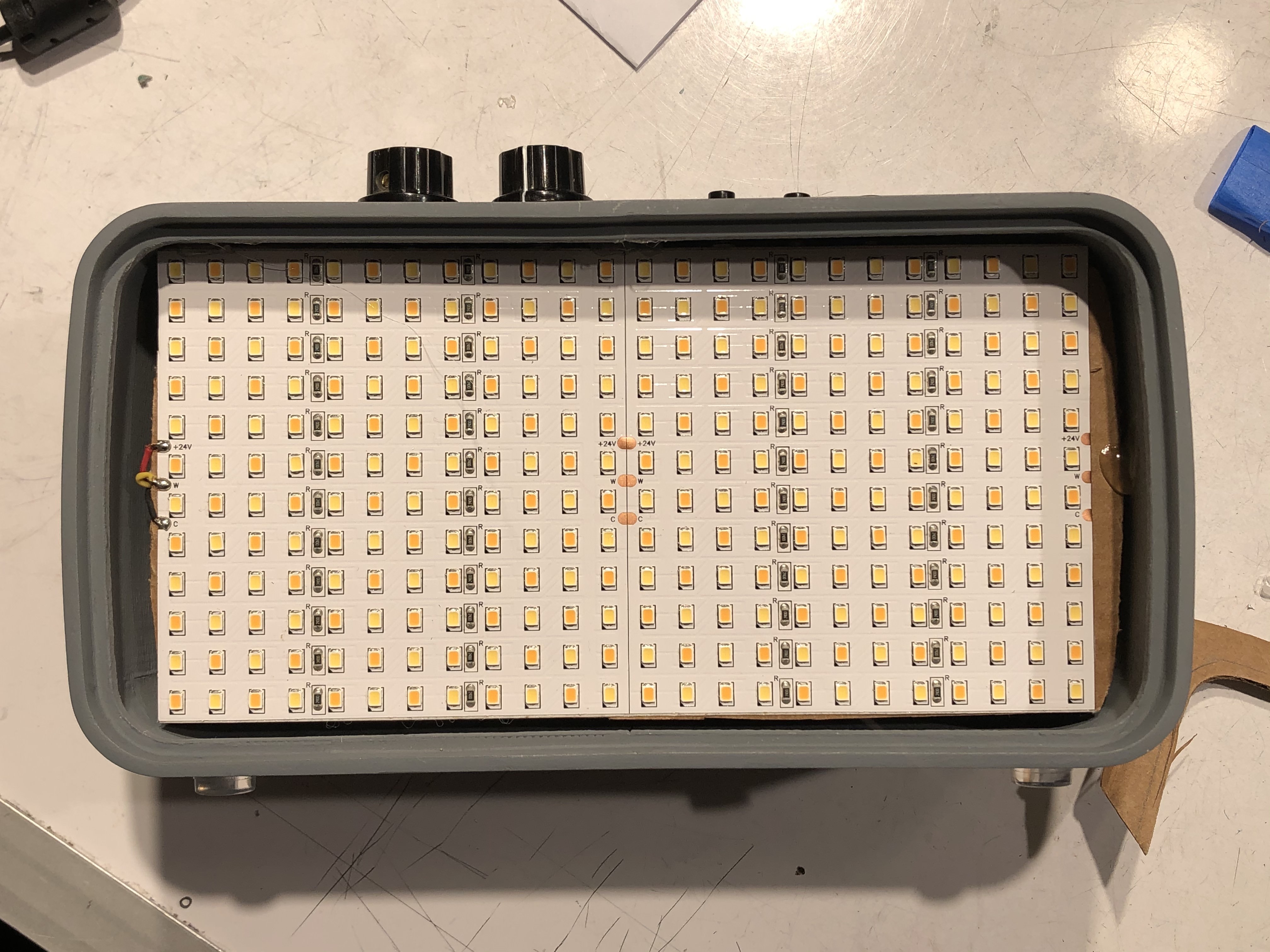
Integrating the LED module.
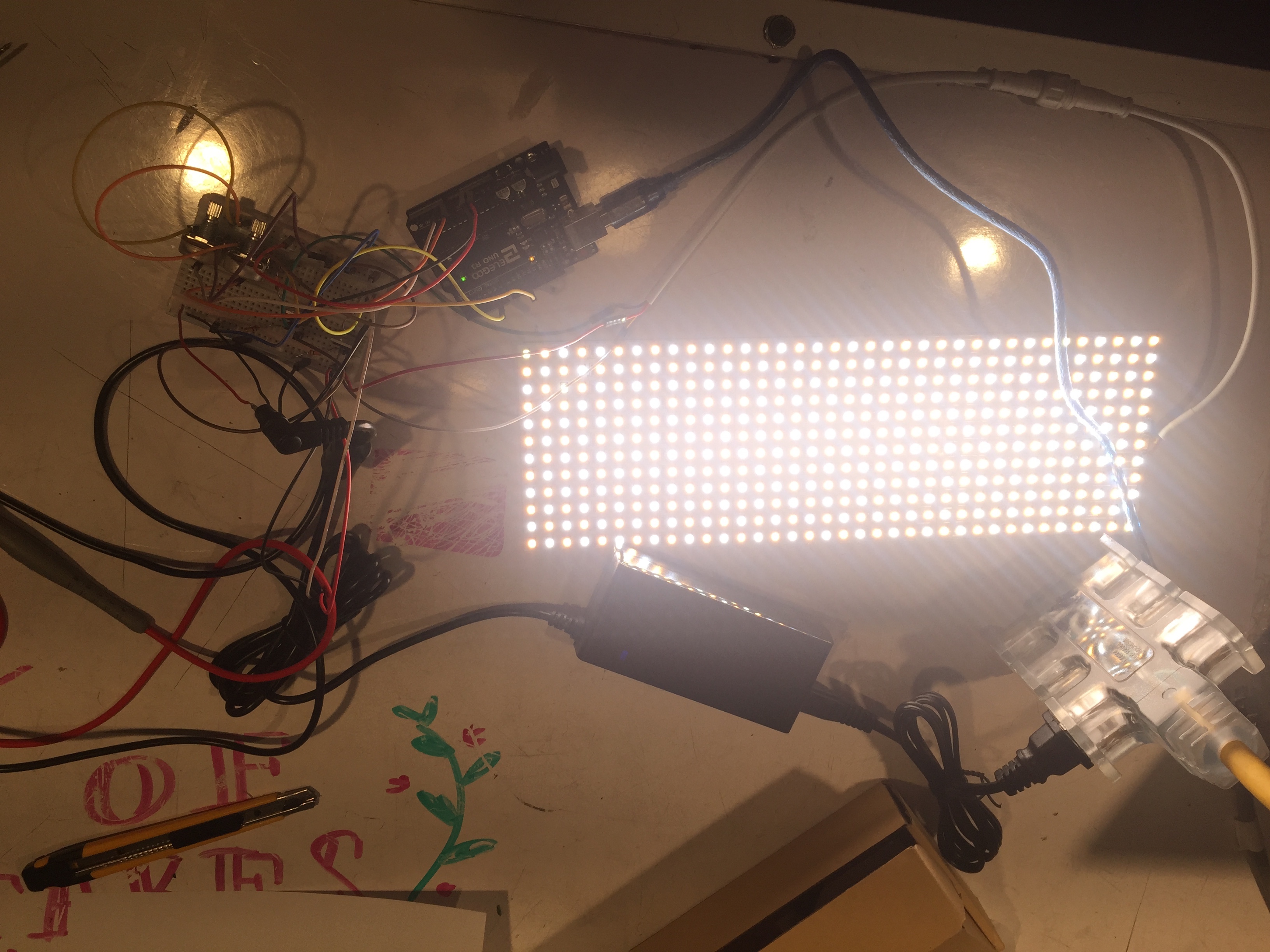
The new LED module is much brighter; closer to natural sunlight than the LED strip used in our prototype.
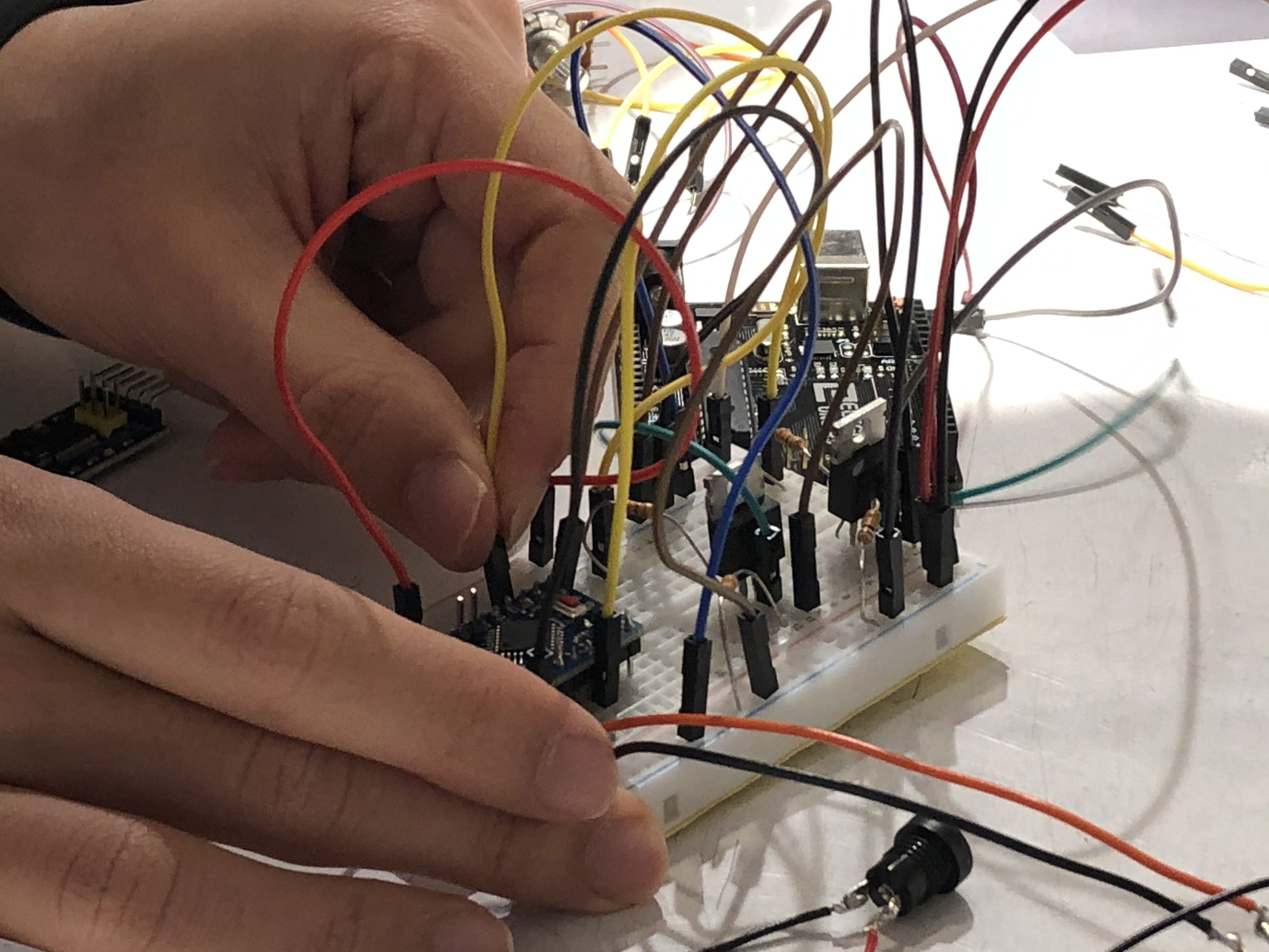
Wiring up the pro mini.
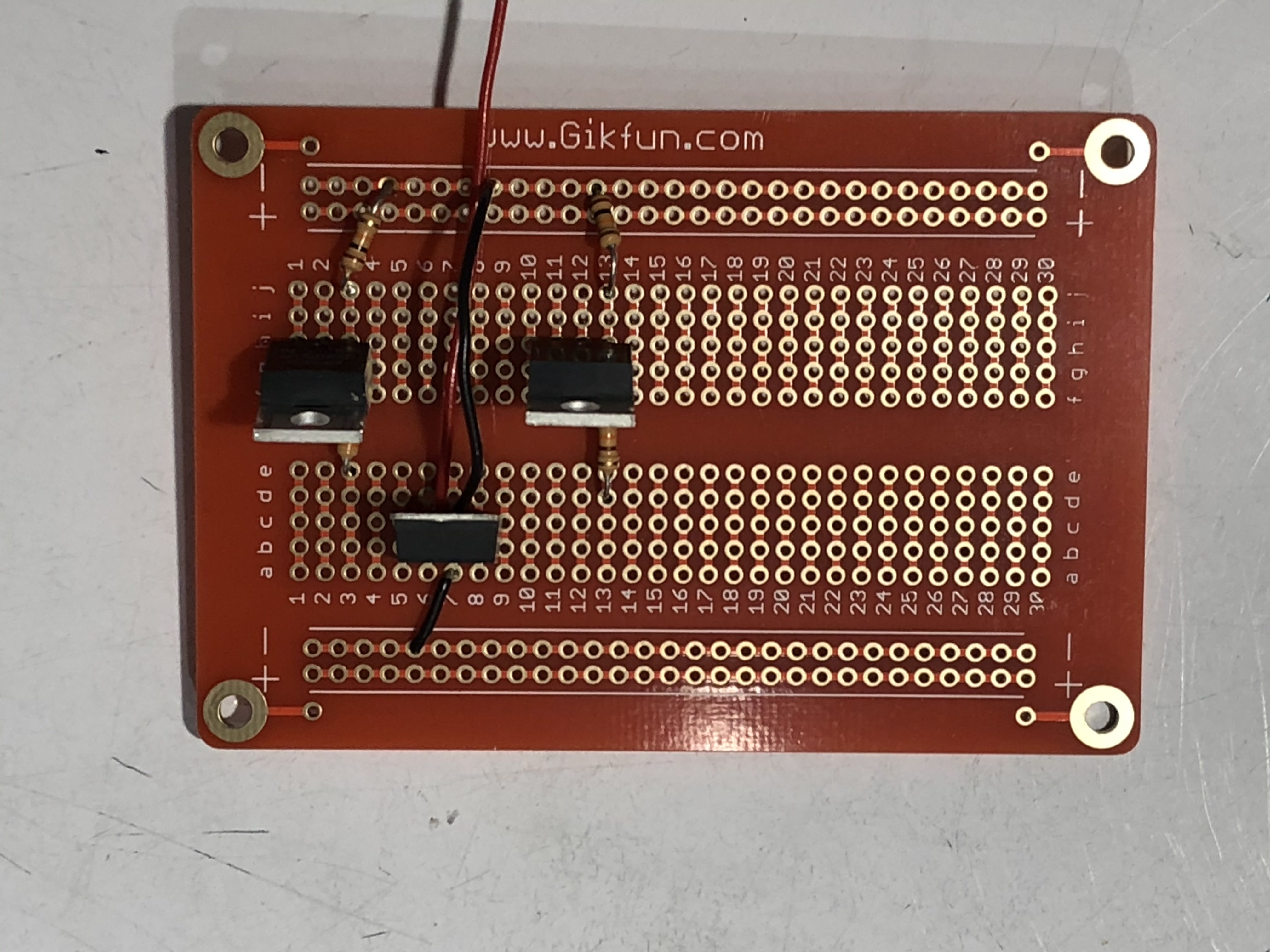
Moving from breadboard to protoboard.
Making progress in soldering the electrical components
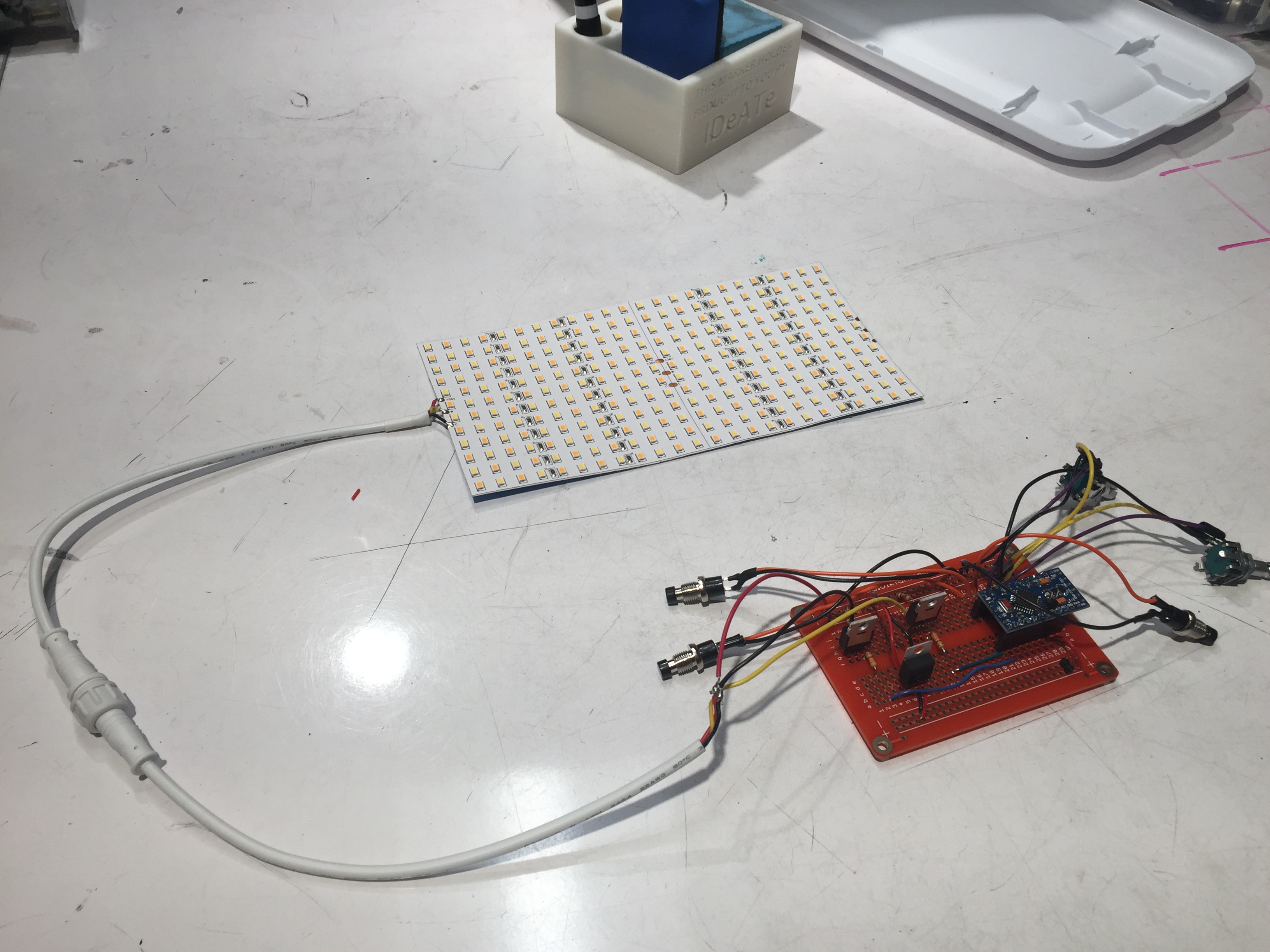
Once all the connections were soldered, we began assembling everything together.
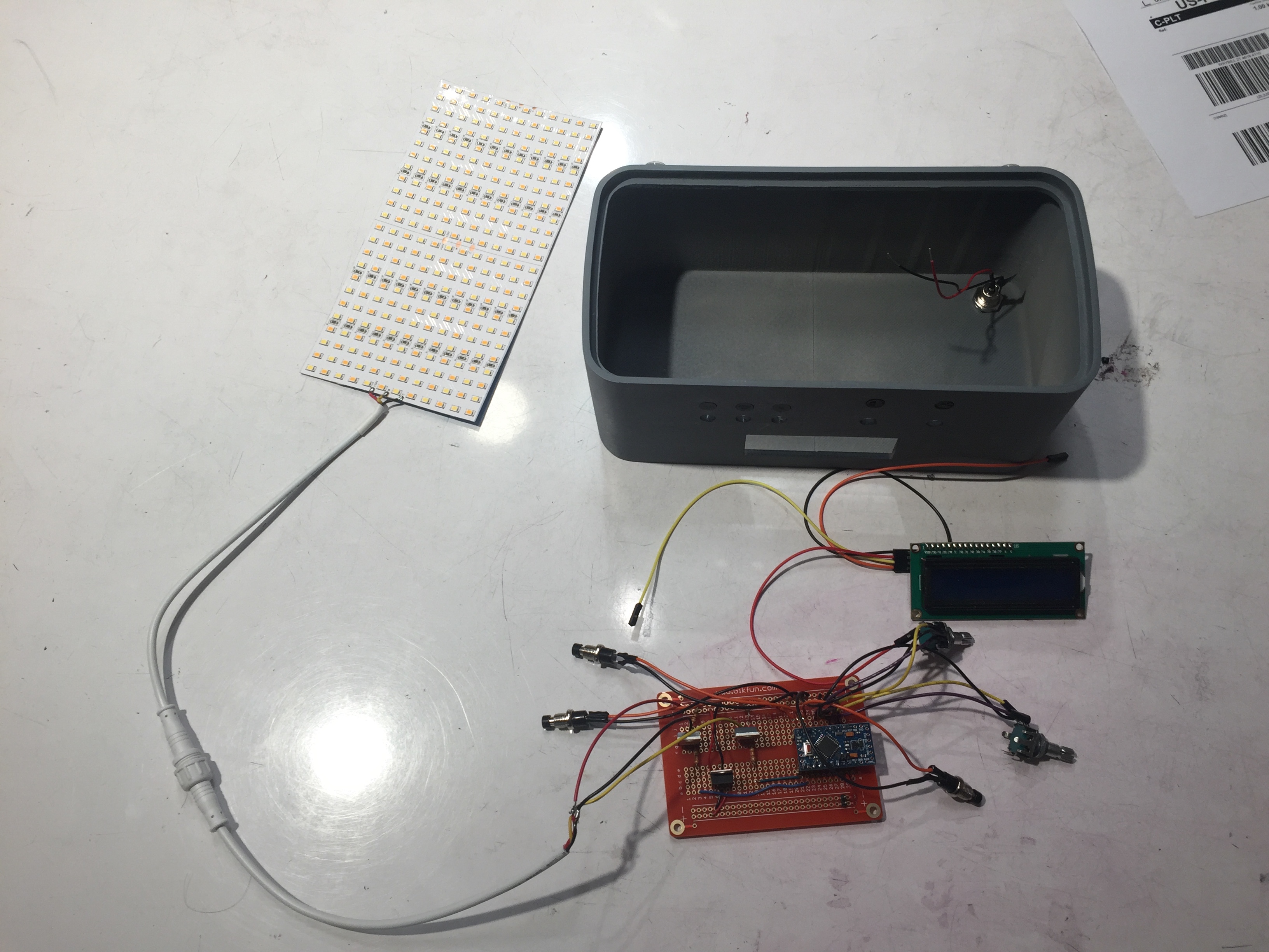
All components ready to be assembled.
We started by securing the LCD screen by hot glueing it in place, then mounting the knobs and buttons. We then glued the protoboard to the back face of the casing to prevent shifting during transport.
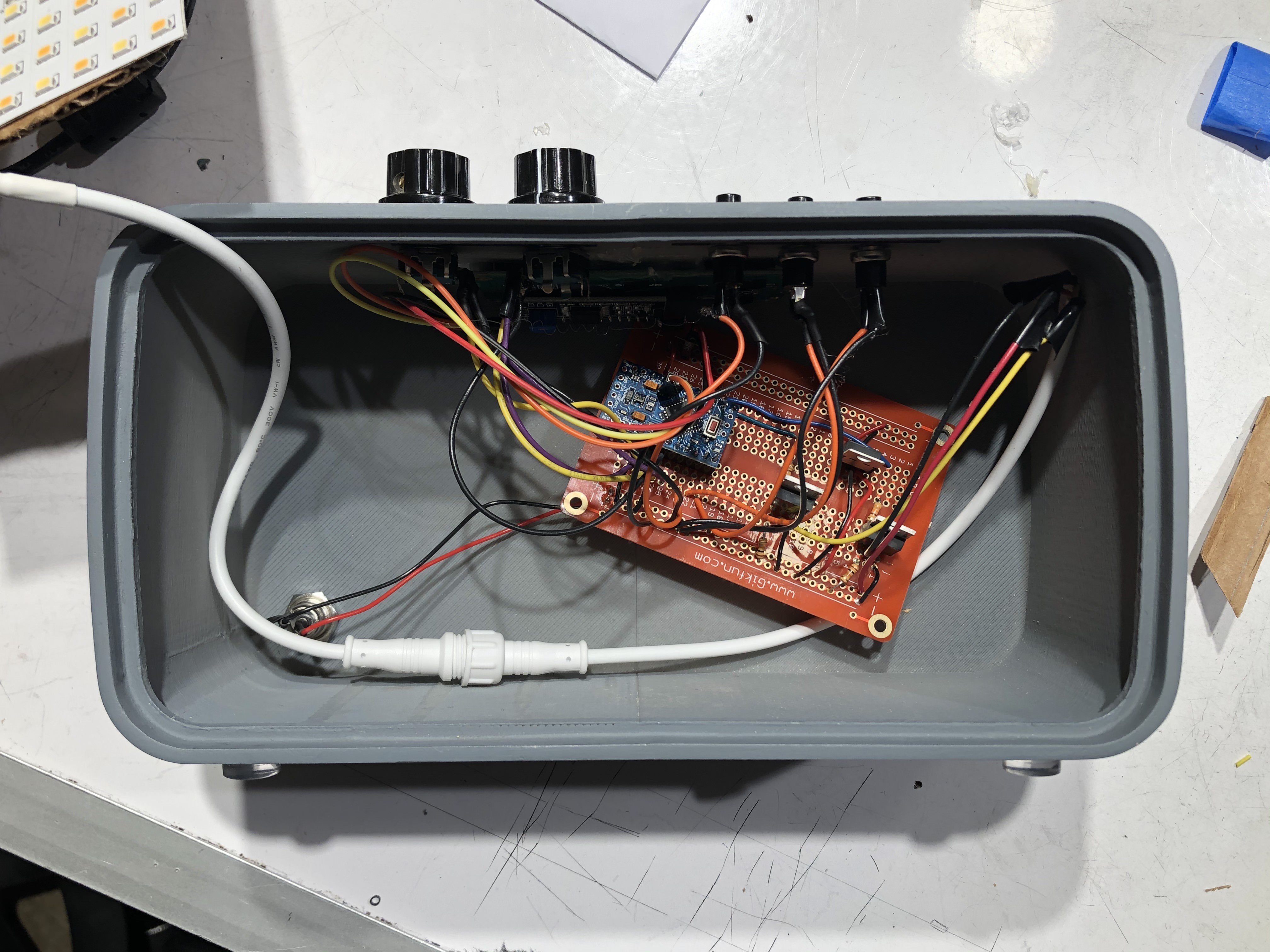
LCD screen, knobs and buttons mounted. Protoboard in place.
Finally, we created a cardboard backing for the LED module and glued that into place. The last step was glueing the frosted acrylic panel in front.
The LED module glued in place on cardboard backing.
In the end, we weren’t able to quite follow our timeline due to the time taken to find and confirm the purchase of the LED panel as well as planning certain milestones for classes that were during Thanksgiving break, but we were able to catch up with some work done on the Sunday (lots of soldering) and Monday (final assembly) before the final critique.
Conclusions and Lessons Learned
Findings from the final critique
A common point of critique was the stand for the device, which some mentioned could easily look dirty or show signs of wear due to its very smooth acrylic material. One of the reviewers remarked that the stand could be made of “wood or another opaque surface” and that both the device stand and our acrylic ‘diffuser’ panel that goes in front of the LED panel could be made of “a material that can take more of a beating.” While the stand had admittedly been designed with the device in mind, it certainly didn’t receive close to the attention from us that the device received, and its the thin, smooth acrylic material turned out to be a poor choice.
One reviewer remarked that we should’ve taken a “closer study of Jeff’s pitch” while another posed the question of “how will Jeff carry this into [the] customer’s home”, probably concerning the handles on the stand not being ideal. Since we hadn’t seen Jeff do a sales pitch, we recognized that this was an unfortunate oversight in our development process, as a number of the other points of criticisms can be drawn from a lack of awareness of its day to day use.
Another point of contention was our choice of placement of the controls, which could affect the sales pitch. While the controls are on the top in our design for ease of accessibility according to Jeff’s desire to put it up against a window, a reviewer said “controls might be better on back”, which would hide them from the client. Both options certainly have advantages, although Jeff seemed pleased enough with the interface as it was.
The 2 adjustable variables of temperature and intensity give the user a lot of direct control and a simpler UI to deal with, but one reviewer did point out that “lighting could be more simulation-oriented”, which is perhaps more user friendly for those less inclined to the control scheme using somewhat technical variables and prefer something they can think of, like a cloudy morning in April (weather, time, season settings vs. color temperature, light intensity settings). If we had looked for and found simple mathematical models that combine all these inputs into something like color temperature and intensity, we recognize that this may have been feasible, although this would ultimately have been a design decision we’d have had to make with Jeff after agreeing initially upon a design fairly similar to our prototype.
Despite a number criticisms, many of the reviewers also had praise for the visual aspect of the design, especially that of the main device (a bit less enthusiasm for the stand). Adjectives like “sleek”, “beautiful”, “well-designed”, “professional”, “fit together”, and “product-like” were used to describe the visual design, and what’s more, Jeff wrote that “I will use this light box daily”. What more could we ask for?
Major takeaways
One of the biggest takeaways we got from working with an older person is that everyone is unique in ways that are often overlooked by stereotypes. We went into the initial meeting with generalizations about the hobbies that an older person might enjoy, or the way that they live their life. However, we were surprised to find that many of these assumptions did not line up. This seemed to be the case for many other groups as well. In our case, Jeff is very active and had no troubles with any physical aspects of his life. He is still highly engaged in his professional life and is very technologically adept. Him and his wife are very social and spend little time in their home. This went against many of our initial assumptions of what we were designing as we expected to create something more closely related to physical needs caused by aging as well as something that would remain at his home. Just as not all young people are addicted to social media and pop culture, older people are also unique in their habits and lifestyles, making it all the more important to research the individual’s particular wants and needs.
We also got a chance to learn from Jeff how our device could play a role in his business and even the entire industry. While there are large studio setups that could do a better job than our device, they’re hardly portable. Our device is both light and compact, making it easy to transport from car to home, but the pragmatic aspect didn’t seem all that novel to us considering similar photography lights did exist, even if they generally didn’t aim for such high light intensities. So we had figured it would be simply a minor addition to the sales pitch to reinforce what Jeff was already telling the customer. But according to Jeff, the device’s role in demonstrations is part of the “sizzle” in a sales pitch that can give a salesman an edge, and, as per Jeff’s own words, “sizzle sells”.
Concluding thoughts
There were several lessons that we took away from this experience.
A variety of technical issues came up throughout the course of developing this device that will serve as helpful experience for the future to prevent mistakes.
Soldering was a challenge at times, especially on the rare occasion that one of the many pins we had to solder in for the Arduino Pro Mini we were using wasn’t connected well by the solder, which made debugging a real challenge, as determining what was a code bug vs. an electrical issue can be hard to see. Bulk soldering can also lead to forgetting about adding heat shrink until both ends of a wire is soldered on, and the potential risk isn’t worth the quicker soldering, since wrapping electrical tape around small wires isn’t fast by any means.
An unfortunate change in the final product from the prototype was switching of the encoder pins from pins 2,4 for one encoder to pins 2,3 and pins 3,5 for the other encoder to pins 4,5. While it appeared to be a seemingly innocuous and more organized change,it turns out that pins 2 and 3 are special interrupt pins on the Arduino Uno (for the prototype) and the Arduino Pro Mini that are especially good for use with encoders. As a result, an encoder output is read best if it has two or at least 1 of these interrupt pins attached, but in this case, 1 encoder got both of the interrupt pins when it would’ve been better for both to get 1. Nevertheless, the ‘faulty’ encoder still works very well if it’s turned slowly enough, so the problem was largely overlooked, as it was an uncommon issue during testing when we hardly turned it very fast.
A few design choices could’ve also potentially enhanced our device.
We hadn’t designed the housing to have a ledges for the LED panel to rest on, which lead to the use of the cardboard backing and hot glue. Additionally, the housing also had no access from the back, so it was effectively impossible to access the internal electronics once it was sealed in by the acrylic panel.
Perhaps embedding the controls in the back could’ve given it an even sleeker look, although the top access is arguably more accessible, but it would’ve been worth considering.
We really should’ve inquired more into how Jeff might use the device on a sales pitch to better customize the stand/carrier. Then we probably would’ve ended up with a sturdier and hopefully easier to carry device.
Overall, creating this device, the result of our extensive efforts, was an engaging and wonderful opportunity for improving skills, gaining experience and enhancing Jeff’s life.
Technical details:
Code:
- <span class="com">/*
- Final Project: Jeffrey's Light
- Description: This code is intended to serve as an interface
- between User Input (consisting of 2 encoders, 3 buttons and an LCD display)
- and configurations for approximate color and relative intensities
- for a high power, bicolor LED panel.
- NOTE: The pins chosen for the encoders are not optimal,
- as one encoder has no interrupt pins (pins 2 and 3), which makes it less effective
- While 2 is optimal, the limited number of interrupt pins makes giving
- each encoder 1 interrupt pin a better balance, therefore pins 2,4 -> Encoder 1 and
- 3,5 -> Encoder 2 or something similar would work best.
- Input:
- Pins|Connection (relevant properties)
- 2 |Encoder 1 (interrupt pin)
- 3 |Encoder 1 (interrupt pin)
- 4 |Encoder 2
- 5 |Encoder 2
- 7 |Button 1
- 8 |Button 2
- 9 |Button 3
- Output:
- Pins|Connections
- 10 |LED Circuit 1 (PWM)
- 11 |(PWM) LED Circuit 2 (PWM)
- A4/A5|LCD Screen (SDA/SCL)
- Resources Used:
- LCD Screen code contains snippets and references to code written by Robert Zacharias at Carnegie Mellon University, rzach@cmu.edu
- released by the author to the public domain, November 2018
- Some Button-related code snippits adapted from my Project 2 code
- Adapted code from public domain examples in Encoder Library by Paul Stoffregen
- https://www.pjrc.com/teensy/td_libs_Encoder.html
- Data on bicolor LED panel used in device from product website
- </span><a href="https://store.yujiintl.com/collections/high-cri-led-strips-ribbon/products/bc-series-high-cri-led-12x-multirow-hybrid-color-temperature-ribbon-unit-1-pcs"><span class="com">BC Series High CRI LED Multirow Hybrid Color Temperature LED Flexible Strip - Pack: 1 pcs</span></a><span class="com">
- Some data on the LEDs, most importantly regarding the balance of LED temperatures
- </span><blockquote class="wp-embedded-content" data-secret="zqRThu8rbL"><a href="https://indiecinemaacademy.com/complexities-of-bicolor-led-lights-an-extensive-color-analysis/"><span class="com">Complexities of Bicolor LED Lights: An Extensive Color Analysis</span></a></blockquote><iframe title="“Complexities of Bicolor LED Lights: An Extensive Color Analysis” — Indie Cinema Academy" class="wp-embedded-content" sandbox="allow-scripts" security="restricted" style="position: absolute; clip: rect(1px, 1px, 1px, 1px); width: 1264px; height: 712.053px;" src="https://indiecinemaacademy.com/complexities-of-bicolor-led-lights-an-extensive-color-analysis/embed/#?secret=zqRThu8rbL" data-secret="zqRThu8rbL" width="600" height="338" frameborder="0" marginwidth="0" marginheight="0" scrolling="no" data-origwidth="600" data-origheight="338"></iframe><span class="com">
- */</span><span class="pln">
- </span><span class="com">#include</span><span class="pln"> </span><span class="str"><Encoder.h></span><span class="pln">
- </span><span class="com">#include</span><span class="pln"> </span><span class="str"><LiquidCrystal_I2C.h></span><span class="pln">
- </span><span class="com">#include</span><span class="pln"> </span><span class="str"><EEPROM.h></span><span class="pln">
- </span><span class="com">//PINS assignments</span><span class="pln">
- </span><span class="typ">Encoder</span><span class="pln"> </span><span class="typ">IntenKnob</span><span class="pun">(</span><span class="lit">2</span><span class="pun">,</span><span class="pln"> </span><span class="lit">3</span><span class="pun">);</span><span class="pln">
- </span><span class="typ">Encoder</span><span class="pln"> </span><span class="typ">ColorKnob</span><span class="pun">(</span><span class="lit">4</span><span class="pun">,</span><span class="pln"> </span><span class="lit">5</span><span class="pun">);</span><span class="pln">
- </span><span class="kwd">const</span><span class="pln"> </span><span class="kwd">int</span><span class="pln"> B1_PIN </span><span class="pun">=</span><span class="pln"> </span><span class="lit">7</span><span class="pun">;</span><span class="pln">
- </span><span class="kwd">const</span><span class="pln"> </span><span class="kwd">int</span><span class="pln"> B2_PIN </span><span class="pun">=</span><span class="pln"> </span><span class="lit">8</span><span class="pun">;</span><span class="pln">
- </span><span class="kwd">const</span><span class="pln"> </span><span class="kwd">int</span><span class="pln"> B3_PIN </span><span class="pun">=</span><span class="pln"> </span><span class="lit">9</span><span class="pun">;</span><span class="pln">
- </span><span class="kwd">const</span><span class="pln"> </span><span class="kwd">int</span><span class="pln"> WARM_LEDS </span><span class="pun">=</span><span class="pln"> </span><span class="lit">10</span><span class="pun">;</span><span class="pln">
- </span><span class="kwd">const</span><span class="pln"> </span><span class="kwd">int</span><span class="pln"> COLD_LEDS </span><span class="pun">=</span><span class="pln"> </span><span class="lit">11</span><span class="pun">;</span><span class="pln">
- </span><span class="com">//Uses SDA/SCL pins, not shown</span><span class="pln">
- </span><span class="typ">LiquidCrystal_I2C</span><span class="pln"> screen</span><span class="pun">(</span><span class="lit">0x27</span><span class="pun">,</span><span class="pln"> </span><span class="lit">16</span><span class="pun">,</span><span class="pln"> </span><span class="lit">2</span><span class="pun">);</span><span class="pln">
- </span><span class="com">//Presets and State Constants//</span><span class="pln">
- </span><span class="com">//State constants based on states set by buttons (effectively an enumeration)</span><span class="pln">
- </span><span class="kwd">const</span><span class="pln"> </span><span class="kwd">byte</span><span class="pln"> CUSTOM </span><span class="pun">=</span><span class="pln"> </span><span class="lit">0</span><span class="pun">;</span><span class="pln">
- </span><span class="kwd">const</span><span class="pln"> </span><span class="kwd">byte</span><span class="pln"> DAYLIGHT </span><span class="pun">=</span><span class="pln"> </span><span class="lit">1</span><span class="pun">;</span><span class="pln">
- </span><span class="kwd">const</span><span class="pln"> </span><span class="kwd">byte</span><span class="pln"> CLOUDY </span><span class="pun">=</span><span class="pln"> </span><span class="lit">2</span><span class="pun">;</span><span class="pln">
- </span><span class="kwd">const</span><span class="pln"> </span><span class="kwd">byte</span><span class="pln"> SUNSET </span><span class="pun">=</span><span class="pln"> </span><span class="lit">3</span><span class="pun">;</span><span class="pln">
- </span><span class="com">//Temperature constants of LEDs in Kelvin</span><span class="pln">
- </span><span class="kwd">const</span><span class="pln"> </span><span class="kwd">int</span><span class="pln"> MAX_TEMP </span><span class="pun">=</span><span class="pln"> </span><span class="lit">6500</span><span class="pun">;</span><span class="pln"> </span><span class="com">//Highest color temperature rating by manufacturer</span><span class="pln">
- </span><span class="kwd">const</span><span class="pln"> </span><span class="kwd">int</span><span class="pln"> MIN_TEMP </span><span class="pun">=</span><span class="pln"> </span><span class="lit">2700</span><span class="pun">;</span><span class="pln"> </span><span class="com">//Lowest color temperature rating by manufacturer</span><span class="pln">
- </span><span class="kwd">const</span><span class="pln"> </span><span class="kwd">int</span><span class="pln"> MID_TEMP </span><span class="pun">=</span><span class="pln"> </span><span class="lit">4100</span><span class="pun">;</span><span class="pln"> </span><span class="com">//LEDs reach peak brightness at this color temperature</span><span class="pln">
- </span><span class="com">//Max - Min = 3800 K</span><span class="pln">
- </span><span class="com">//LED Presets</span><span class="pln">
- </span><span class="kwd">int</span><span class="pln"> DAY_TEMP </span><span class="pun">=</span><span class="pln"> </span><span class="lit">6000</span><span class="pun">;</span><span class="pln">
- </span><span class="kwd">float</span><span class="pln"> DAY_INTEN </span><span class="pun">=</span><span class="pln"> </span><span class="lit">0.86</span><span class="pun">;</span><span class="pln">
- </span><span class="kwd">int</span><span class="pln"> CLOUDY_TEMP </span><span class="pun">=</span><span class="pln"> </span><span class="lit">6500</span><span class="pun">;</span><span class="pln">
- </span><span class="kwd">float</span><span class="pln"> CLOUD_INTEN </span><span class="pun">=</span><span class="pln"> </span><span class="lit">0.02</span><span class="pun">;</span><span class="pln">
- </span><span class="kwd">int</span><span class="pln"> SUNSET_TEMP </span><span class="pun">=</span><span class="pln"> </span><span class="lit">3000</span><span class="pun">;</span><span class="pln">
- </span><span class="kwd">float</span><span class="pln"> SUNSET_INTEN </span><span class="pun">=</span><span class="pln"> </span><span class="lit">0.2</span><span class="pun">;</span><span class="pln">
- </span><span class="com">//Commented out struct below is present in device code but is not used</span><span class="pln">
- </span><span class="com">/*
- struct saveData {
- int DAY_TEMPs;
- float DAY_INTENs;
- int CLOUDY_TEMPs;
- float CLOUD_INTENs;
- int SUNSET_TEMPs;
- float SUNSET_INTENs;
- };
- */</span><span class="pln">
- </span><span class="com">//Variables//</span><span class="pln">
- </span><span class="com">//I/O Constants//</span><span class="pln">
- </span><span class="com">//Presets chosen to define the range of encoder values</span><span class="pln">
- </span><span class="com">//50 intervals for intensity ->0.02 per encoder 'tick'</span><span class="pln">
- </span><span class="com">//38 intervals for temperature -> 100 K per encoder 'tick'</span><span class="pln">
- </span><span class="kwd">const</span><span class="pln"> </span><span class="kwd">int</span><span class="pln"> </span><span class="typ">EncIntenRange</span><span class="pln"> </span><span class="pun">=</span><span class="pln"> </span><span class="lit">50</span><span class="pun">;</span><span class="pln">
- </span><span class="kwd">const</span><span class="pln"> </span><span class="kwd">int</span><span class="pln"> </span><span class="typ">EncColorRange</span><span class="pln"> </span><span class="pun">=</span><span class="pln"> </span><span class="lit">38</span><span class="pun">;</span><span class="pln">
- </span><span class="com">//Constants that serve as delimeters for milliseconds it takes to recognize either</span><span class="pln">
- </span><span class="com">//a press (50ms) for setting light to config preset or a hold (2000ms) to edit that preset</span><span class="pln">
- </span><span class="kwd">const</span><span class="pln"> </span><span class="kwd">int</span><span class="pln"> bPressTime </span><span class="pun">=</span><span class="pln"> </span><span class="lit">50</span><span class="pun">;</span><span class="pln">
- </span><span class="kwd">const</span><span class="pln"> </span><span class="kwd">int</span><span class="pln"> bEditTime </span><span class="pun">=</span><span class="pln"> </span><span class="lit">2000</span><span class="pun">;</span><span class="pln">
- </span><span class="com">//Used for storing previous Intensity and Color values between loop calls</span><span class="pln">
- </span><span class="kwd">int</span><span class="pln"> lastInten</span><span class="pun">,</span><span class="pln"> lastColor </span><span class="pun">=</span><span class="pln"> </span><span class="pun">-</span><span class="lit">1</span><span class="pun">;</span><span class="pln">
- </span><span class="com">//Keeps track of how long any of the three buttons have been held</span><span class="pln">
- </span><span class="kwd">int</span><span class="pln"> buttonTimes</span><span class="pun">[</span><span class="lit">3</span><span class="pun">];</span><span class="pln">
- </span><span class="com">//These store the output values to the PWM pins (index 0 is warm LEDs; index 1 is cold LEDs)</span><span class="pln">
- </span><span class="kwd">int</span><span class="pln"> </span><span class="typ">PWMs</span><span class="pun">[</span><span class="lit">2</span><span class="pun">];</span><span class="pln">
- </span><span class="com">//Time Variables//</span><span class="pln">
- </span><span class="com">//Used to keep track of elapsed time between loop calls</span><span class="pln">
- </span><span class="kwd">unsigned</span><span class="pln"> </span><span class="kwd">long</span><span class="pln"> lastMillis</span><span class="pun">;</span><span class="pln">
- </span><span class="com">//A constant delay value (should be a constant variable) at the end of loop calls as it should reduce LCD flickering. Possibly unnecessary.</span><span class="pln">
- </span><span class="kwd">int</span><span class="pln"> delayTime </span><span class="pun">=</span><span class="pln"> </span><span class="lit">10</span><span class="pun">;</span><span class="pln">
- </span><span class="com">//State Variables//</span><span class="pln">
- </span><span class="com">//The state of the device in non-editing mode (not relevant while editing)</span><span class="pln">
- </span><span class="kwd">byte</span><span class="pln"> state </span><span class="pun">=</span><span class="pln"> CUSTOM</span><span class="pun">;</span><span class="pln">
- </span><span class="com">//The state of the device during editing (not relevant when non-editing)</span><span class="pln">
- </span><span class="kwd">byte</span><span class="pln"> </span><span class="typ">EditState</span><span class="pln"> </span><span class="pun">=</span><span class="pln"> CUSTOM</span><span class="pun">;</span><span class="pln"> </span><span class="com">//Initialized to not an editable state</span><span class="pln">
- </span><span class="com">//Determines if the device is in an editing state or not.</span><span class="pln">
- </span><span class="kwd">bool</span><span class="pln"> isEditing </span><span class="pun">=</span><span class="pln"> </span><span class="kwd">false</span><span class="pun">;</span><span class="pln">
- </span><span class="com">//A flag to determine whether to redraw the LCD screen or not</span><span class="pln">
- </span><span class="kwd">bool</span><span class="pln"> dirtyLCD </span><span class="pun">=</span><span class="pln"> </span><span class="kwd">true</span><span class="pun">;</span><span class="pln">
- </span><span class="com">//Initialization Constants//</span><span class="pln">
- </span><span class="com">//Initialization Temperature and color (a soft white glow to indicate activity without being blinding)</span><span class="pln">
- </span><span class="kwd">const</span><span class="pln"> </span><span class="kwd">int</span><span class="pln"> </span><span class="typ">InitTemp</span><span class="pln"> </span><span class="pun">=</span><span class="pln"> </span><span class="lit">5000</span><span class="pun">;</span><span class="pln">
- </span><span class="kwd">const</span><span class="pln"> </span><span class="kwd">float</span><span class="pln"> </span><span class="typ">InitInt</span><span class="pln"> </span><span class="pun">=</span><span class="pln"> </span><span class="lit">0.02</span><span class="pun">;</span><span class="pln">
- </span><span class="kwd">void</span><span class="pln"> setup</span><span class="pun">()</span><span class="pln"> </span><span class="pun">{</span><span class="pln">
- </span><span class="com">//Initialize button pins</span><span class="pln">
- pinMode</span><span class="pun">(</span><span class="pln">B1_PIN</span><span class="pun">,</span><span class="pln"> INPUT_PULLUP</span><span class="pun">);</span><span class="pln">
- pinMode</span><span class="pun">(</span><span class="pln">B2_PIN</span><span class="pun">,</span><span class="pln"> INPUT_PULLUP</span><span class="pun">);</span><span class="pln">
- pinMode</span><span class="pun">(</span><span class="pln">B3_PIN</span><span class="pun">,</span><span class="pln"> INPUT_PULLUP</span><span class="pun">);</span><span class="pln">
- </span><span class="com">//Initialize LED (PWM) pins</span><span class="pln">
- pinMode</span><span class="pun">(</span><span class="pln">WARM_LEDS</span><span class="pun">,</span><span class="pln"> OUTPUT</span><span class="pun">);</span><span class="pln">
- pinMode</span><span class="pun">(</span><span class="pln">COLD_LEDS</span><span class="pun">,</span><span class="pln"> OUTPUT</span><span class="pun">);</span><span class="pln">
- lastMillis </span><span class="pun">=</span><span class="pln"> millis</span><span class="pun">();</span><span class="pln">
- </span><span class="com">//Loads the 3 presets from EEPROM</span><span class="pln">
- loadPreset</span><span class="pun">();</span><span class="pln">
- </span><span class="com">//Initialize the screen with relevant commands</span><span class="pln">
- screen</span><span class="pun">.</span><span class="pln">init</span><span class="pun">();</span><span class="pln">
- screen</span><span class="pun">.</span><span class="pln">backlight</span><span class="pun">();</span><span class="pln">
- screen</span><span class="pun">.</span><span class="pln">clear</span><span class="pun">();</span><span class="pln">
- screen</span><span class="pun">.</span><span class="pln">home</span><span class="pun">();</span><span class="pln">
- </span><span class="com">//Initial color and intensity is set in the relevant 'encoder objects'.</span><span class="pln">
- </span><span class="typ">IntenKnob</span><span class="pun">.</span><span class="pln">write</span><span class="pun">(</span><span class="pln">rotFromInten</span><span class="pun">(</span><span class="typ">InitInt</span><span class="pun">));</span><span class="pln">
- </span><span class="typ">ColorKnob</span><span class="pun">.</span><span class="pln">write</span><span class="pun">(</span><span class="pln">rotFromTemp</span><span class="pun">(</span><span class="typ">InitTemp</span><span class="pun">));</span><span class="pln">
- </span><span class="pun">}</span><span class="pln">
- </span><span class="kwd">void</span><span class="pln"> loop</span><span class="pun">()</span><span class="pln"> </span><span class="pun">{</span><span class="pln">
- </span><span class="com">//Reads the encoder values</span><span class="pln">
- </span><span class="kwd">int</span><span class="pln"> intenvalue </span><span class="pun">=</span><span class="pln"> </span><span class="typ">IntenKnob</span><span class="pun">.</span><span class="pln">read</span><span class="pun">();</span><span class="pln">
- </span><span class="kwd">int</span><span class="pln"> colorvalue </span><span class="pun">=</span><span class="pln"> </span><span class="typ">ColorKnob</span><span class="pun">.</span><span class="pln">read</span><span class="pun">();</span><span class="pln">
- </span><span class="com">//Prevents the encoders from leaving the allowed range</span><span class="pln">
- </span><span class="kwd">if</span><span class="pln"> </span><span class="pun">(</span><span class="pln">intenvalue </span><span class="pun">></span><span class="pln"> </span><span class="lit">0</span><span class="pun">)</span><span class="pln"> </span><span class="pun">{</span><span class="pln">
- </span><span class="typ">IntenKnob</span><span class="pun">.</span><span class="pln">write</span><span class="pun">(</span><span class="lit">0</span><span class="pun">);</span><span class="pln">
- intenvalue </span><span class="pun">=</span><span class="pln"> </span><span class="lit">0</span><span class="pun">;</span><span class="pln">
- </span><span class="pun">}</span><span class="pln">
- </span><span class="kwd">if</span><span class="pln"> </span><span class="pun">(</span><span class="pln">colorvalue </span><span class="pun">></span><span class="pln"> </span><span class="lit">0</span><span class="pun">)</span><span class="pln"> </span><span class="pun">{</span><span class="pln">
- </span><span class="typ">ColorKnob</span><span class="pun">.</span><span class="pln">write</span><span class="pun">(</span><span class="lit">0</span><span class="pun">);</span><span class="pln">
- colorvalue </span><span class="pun">=</span><span class="pln"> </span><span class="lit">0</span><span class="pun">;</span><span class="pln">
- </span><span class="pun">}</span><span class="pln">
- </span><span class="kwd">if</span><span class="pln"> </span><span class="pun">(</span><span class="pln">intenvalue </span><span class="pun"><</span><span class="pln"> </span><span class="pun">-</span><span class="typ">EncIntenRange</span><span class="pun">)</span><span class="pln"> </span><span class="pun">{</span><span class="pln">
- </span><span class="typ">IntenKnob</span><span class="pun">.</span><span class="pln">write</span><span class="pun">(-</span><span class="typ">EncIntenRange</span><span class="pun">);</span><span class="pln">
- intenvalue </span><span class="pun">=</span><span class="pln"> </span><span class="pun">-</span><span class="typ">EncIntenRange</span><span class="pun">;</span><span class="pln">
- </span><span class="pun">}</span><span class="pln">
- </span><span class="kwd">if</span><span class="pln"> </span><span class="pun">(</span><span class="pln">colorvalue </span><span class="pun"><</span><span class="pln"> </span><span class="pun">-</span><span class="typ">EncColorRange</span><span class="pun">)</span><span class="pln"> </span><span class="pun">{</span><span class="pln">
- </span><span class="typ">ColorKnob</span><span class="pun">.</span><span class="pln">write</span><span class="pun">(-</span><span class="typ">EncColorRange</span><span class="pun">);</span><span class="pln">
- colorvalue </span><span class="pun">=</span><span class="pln"> </span><span class="pun">-</span><span class="typ">EncColorRange</span><span class="pun">;</span><span class="pln">
- </span><span class="pun">}</span><span class="pln">
- </span><span class="com">//Record Encoder input (negative due to clockwise motion decreasing the encoder values)</span><span class="pln">
- </span><span class="kwd">int</span><span class="pln"> cin </span><span class="pun">=</span><span class="pln"> </span><span class="pun">-</span><span class="pln">colorvalue</span><span class="pun">;</span><span class="pln">
- </span><span class="kwd">int</span><span class="pln"> inn </span><span class="pun">=</span><span class="pln"> </span><span class="pun">-</span><span class="pln">intenvalue</span><span class="pun">;</span><span class="pln">
- </span><span class="com">//This variable is largely irrelevant unless in edit mode, in which case inputs that make it</span><span class="pln">
- </span><span class="com">//true will lead to the leaving of edit mode.</span><span class="pln">
- </span><span class="kwd">bool</span><span class="pln"> stopEdit </span><span class="pun">=</span><span class="pln"> </span><span class="kwd">false</span><span class="pun">;</span><span class="pln">
- </span><span class="com">//Response to changes between current and previous encoder positions</span><span class="pln">
- </span><span class="kwd">if</span><span class="pln"> </span><span class="pun">(</span><span class="pln">cin </span><span class="pun">!=</span><span class="pln"> lastColor </span><span class="pun">||</span><span class="pln"> inn </span><span class="pun">!=</span><span class="pln"> lastInten</span><span class="pun">)</span><span class="pln"> </span><span class="pun">{</span><span class="pln">
- dirtyLCD </span><span class="pun">=</span><span class="pln"> </span><span class="kwd">true</span><span class="pun">;</span><span class="pln">
- </span><span class="kwd">if</span><span class="pln"> </span><span class="pun">(!</span><span class="pln">isEditing</span><span class="pun">)</span><span class="pln">state </span><span class="pun">=</span><span class="pln"> CUSTOM</span><span class="pun">;</span><span class="pln"> </span><span class="com">//Only while editing does state changing to custom matter</span><span class="pln">
- </span><span class="pun">}</span><span class="pln">
- </span><span class="com">//Set state or editing based on button input</span><span class="pln">
- </span><span class="kwd">if</span><span class="pln"> </span><span class="pun">(!</span><span class="pln">digitalRead</span><span class="pun">(</span><span class="pln">B1_PIN</span><span class="pun">))</span><span class="pln"> </span><span class="pun">{</span><span class="pln">
- buttonTimes</span><span class="pun">[</span><span class="lit">0</span><span class="pun">]</span><span class="pln"> </span><span class="pun">+=</span><span class="pln"> millis</span><span class="pun">()</span><span class="pln"> </span><span class="pun">-</span><span class="pln"> lastMillis</span><span class="pun">;</span><span class="pln">
- </span><span class="kwd">if</span><span class="pln"> </span><span class="pun">(</span><span class="pln">buttonTimes</span><span class="pun">[</span><span class="lit">0</span><span class="pun">]</span><span class="pln"> </span><span class="pun">></span><span class="pln"> bPressTime</span><span class="pun">)</span><span class="pln"> </span><span class="pun">{</span><span class="pln">
- </span><span class="kwd">if</span><span class="pln"> </span><span class="pun">(</span><span class="pln">state </span><span class="pun">!=</span><span class="pln"> DAYLIGHT</span><span class="pun">)</span><span class="pln">dirtyLCD </span><span class="pun">=</span><span class="pln"> </span><span class="kwd">true</span><span class="pun">;</span><span class="pln">
- state </span><span class="pun">=</span><span class="pln"> DAYLIGHT</span><span class="pun">;</span><span class="pln">
- </span><span class="kwd">if</span><span class="pln"> </span><span class="pun">(</span><span class="pln">buttonTimes</span><span class="pun">[</span><span class="lit">0</span><span class="pun">]</span><span class="pln"> </span><span class="pun"><</span><span class="pln"> bEditTime</span><span class="pun">)</span><span class="pln">stopEdit </span><span class="pun">=</span><span class="pln"> </span><span class="kwd">true</span><span class="pun">;</span><span class="pln">
- </span><span class="pun">}</span><span class="pln">
- </span><span class="pun">}</span><span class="pln">
- </span><span class="kwd">else</span><span class="pln"> buttonTimes</span><span class="pun">[</span><span class="lit">0</span><span class="pun">]</span><span class="pln"> </span><span class="pun">=</span><span class="pln"> </span><span class="lit">0</span><span class="pun">;</span><span class="pln">
- </span><span class="kwd">if</span><span class="pln"> </span><span class="pun">(!</span><span class="pln">digitalRead</span><span class="pun">(</span><span class="pln">B2_PIN</span><span class="pun">))</span><span class="pln"> </span><span class="pun">{</span><span class="pln">
- buttonTimes</span><span class="pun">[</span><span class="lit">1</span><span class="pun">]</span><span class="pln"> </span><span class="pun">+=</span><span class="pln"> millis</span><span class="pun">()</span><span class="pln"> </span><span class="pun">-</span><span class="pln"> lastMillis</span><span class="pun">;</span><span class="pln">
- </span><span class="kwd">if</span><span class="pln"> </span><span class="pun">(</span><span class="pln">buttonTimes</span><span class="pun">[</span><span class="lit">1</span><span class="pun">]</span><span class="pln"> </span><span class="pun">></span><span class="pln"> bPressTime</span><span class="pun">)</span><span class="pln"> </span><span class="pun">{</span><span class="pln">
- </span><span class="kwd">if</span><span class="pln"> </span><span class="pun">(</span><span class="pln">state </span><span class="pun">!=</span><span class="pln"> CLOUDY</span><span class="pun">)</span><span class="pln">dirtyLCD </span><span class="pun">=</span><span class="pln"> </span><span class="kwd">true</span><span class="pun">;</span><span class="pln">
- state </span><span class="pun">=</span><span class="pln"> CLOUDY</span><span class="pun">;</span><span class="pln">
- </span><span class="kwd">if</span><span class="pln"> </span><span class="pun">(</span><span class="pln">buttonTimes</span><span class="pun">[</span><span class="lit">1</span><span class="pun">]</span><span class="pln"> </span><span class="pun"><</span><span class="pln"> bEditTime</span><span class="pun">)</span><span class="pln">stopEdit </span><span class="pun">=</span><span class="pln"> </span><span class="kwd">true</span><span class="pun">;</span><span class="pln">
- </span><span class="pun">}</span><span class="pln">
- </span><span class="pun">}</span><span class="pln">
- </span><span class="kwd">else</span><span class="pln"> buttonTimes</span><span class="pun">[</span><span class="lit">1</span><span class="pun">]</span><span class="pln"> </span><span class="pun">=</span><span class="pln"> </span><span class="lit">0</span><span class="pun">;</span><span class="pln">
- </span><span class="kwd">if</span><span class="pln"> </span><span class="pun">(!</span><span class="pln">digitalRead</span><span class="pun">(</span><span class="pln">B3_PIN</span><span class="pun">))</span><span class="pln"> </span><span class="pun">{</span><span class="pln">
- buttonTimes</span><span class="pun">[</span><span class="lit">2</span><span class="pun">]</span><span class="pln"> </span><span class="pun">+=</span><span class="pln"> millis</span><span class="pun">()</span><span class="pln"> </span><span class="pun">-</span><span class="pln"> lastMillis</span><span class="pun">;</span><span class="pln">
- </span><span class="kwd">if</span><span class="pln"> </span><span class="pun">(</span><span class="pln">buttonTimes</span><span class="pun">[</span><span class="lit">2</span><span class="pun">]</span><span class="pln"> </span><span class="pun">></span><span class="pln"> bPressTime</span><span class="pun">)</span><span class="pln"> </span><span class="pun">{</span><span class="pln">
- </span><span class="kwd">if</span><span class="pln"> </span><span class="pun">(</span><span class="pln">state </span><span class="pun">!=</span><span class="pln"> SUNSET</span><span class="pun">)</span><span class="pln">dirtyLCD </span><span class="pun">=</span><span class="pln"> </span><span class="kwd">true</span><span class="pun">;</span><span class="pln">
- state </span><span class="pun">=</span><span class="pln"> SUNSET</span><span class="pun">;</span><span class="pln">
- </span><span class="kwd">if</span><span class="pln"> </span><span class="pun">(</span><span class="pln">buttonTimes</span><span class="pun">[</span><span class="lit">2</span><span class="pun">]</span><span class="pln"> </span><span class="pun"><</span><span class="pln"> bEditTime</span><span class="pun">)</span><span class="pln">stopEdit </span><span class="pun">=</span><span class="pln"> </span><span class="kwd">true</span><span class="pun">;</span><span class="pln">
- </span><span class="pun">}</span><span class="pln">
- </span><span class="pun">}</span><span class="pln">
- </span><span class="kwd">else</span><span class="pln"> buttonTimes</span><span class="pun">[</span><span class="lit">2</span><span class="pun">]</span><span class="pln"> </span><span class="pun">=</span><span class="pln"> </span><span class="lit">0</span><span class="pun">;</span><span class="pln">
- </span><span class="com">//LastMillis is only used above, so we can set it again afterwards</span><span class="pln">
- lastMillis </span><span class="pun">=</span><span class="pln"> millis</span><span class="pun">();</span><span class="pln">
- </span><span class="com">//If any buttons been held for long enough, then device enters Edit Mode</span><span class="pln">
- </span><span class="kwd">if</span><span class="pln"> </span><span class="pun">(</span><span class="pln">buttonTimes</span><span class="pun">[</span><span class="lit">0</span><span class="pun">]</span><span class="pln"> </span><span class="pun">></span><span class="pln"> bEditTime </span><span class="pun">||</span><span class="pln"> buttonTimes</span><span class="pun">[</span><span class="lit">1</span><span class="pun">]</span><span class="pln"> </span><span class="pun">></span><span class="pln"> bEditTime </span><span class="pun">||</span><span class="pln"> buttonTimes</span><span class="pun">[</span><span class="lit">2</span><span class="pun">]</span><span class="pln"> </span><span class="pun">></span><span class="pln"> bEditTime</span><span class="pun">)</span><span class="pln"> </span><span class="pun">{</span><span class="pln">
- </span><span class="kwd">if</span><span class="pln"> </span><span class="pun">(!</span><span class="pln">isEditing</span><span class="pun">)</span><span class="pln">dirtyLCD </span><span class="pun">=</span><span class="pln"> </span><span class="kwd">true</span><span class="pun">;</span><span class="pln">
- stopEdit </span><span class="pun">=</span><span class="pln"> </span><span class="kwd">false</span><span class="pun">;</span><span class="pln">
- isEditing </span><span class="pun">=</span><span class="pln"> </span><span class="kwd">true</span><span class="pun">;</span><span class="pln">
- </span><span class="typ">EditState</span><span class="pln"> </span><span class="pun">=</span><span class="pln"> state</span><span class="pun">;</span><span class="pln">
- </span><span class="pun">}</span><span class="pln">
- </span><span class="com">//Initializes the string so it can be used later to print to the LCD</span><span class="pln">
- </span><span class="typ">String</span><span class="pln"> stateStr</span><span class="pun">;</span><span class="pln">
- </span><span class="kwd">if</span><span class="pln"> </span><span class="pun">(!</span><span class="pln">isEditing</span><span class="pun">)</span><span class="pln"> </span><span class="pun">{</span><span class="pln">
- </span><span class="kwd">switch</span><span class="pln"> </span><span class="pun">(</span><span class="pln">state</span><span class="pun">)</span><span class="pln"> </span><span class="pun">{</span><span class="pln">
- </span><span class="kwd">case</span><span class="pln"> CUSTOM</span><span class="pun">:</span><span class="pln">
- stateStr </span><span class="pun">=</span><span class="pln"> </span><span class="str">"CUSTOM"</span><span class="pun">;</span><span class="pln">
- </span><span class="kwd">break</span><span class="pun">;</span><span class="pln">
- </span><span class="com">//Daylight presets are converted to Encoder presets</span><span class="pln">
- </span><span class="kwd">case</span><span class="pln"> DAYLIGHT</span><span class="pun">:</span><span class="pln">
- cin </span><span class="pun">=</span><span class="pln"> </span><span class="pun">(</span><span class="pln">DAY_TEMP </span><span class="pun">-</span><span class="pln"> MIN_TEMP</span><span class="pun">)</span><span class="pln"> </span><span class="pun">/</span><span class="pln"> </span><span class="pun">((</span><span class="pln">MAX_TEMP </span><span class="pun">-</span><span class="pln"> MIN_TEMP</span><span class="pun">)</span><span class="pln"> </span><span class="pun">/</span><span class="pln"> </span><span class="typ">EncColorRange</span><span class="pun">);</span><span class="pln">
- inn </span><span class="pun">=</span><span class="pln"> </span><span class="pun">(</span><span class="kwd">int</span><span class="pun">)(</span><span class="typ">EncIntenRange</span><span class="pln"> </span><span class="pun">*</span><span class="pln"> DAY_INTEN</span><span class="pun">);</span><span class="pln">
- stateStr </span><span class="pun">=</span><span class="pln"> </span><span class="str">"SUNNY"</span><span class="pun">;</span><span class="pln">
- </span><span class="kwd">break</span><span class="pun">;</span><span class="pln">
- </span><span class="com">//Cloudy presets are converted to Encoder presets</span><span class="pln">
- </span><span class="kwd">case</span><span class="pln"> CLOUDY</span><span class="pun">:</span><span class="pln">
- cin </span><span class="pun">=</span><span class="pln"> </span><span class="pun">(</span><span class="pln">CLOUDY_TEMP </span><span class="pun">-</span><span class="pln"> MIN_TEMP</span><span class="pun">)</span><span class="pln"> </span><span class="pun">/</span><span class="pln"> </span><span class="pun">((</span><span class="pln">MAX_TEMP </span><span class="pun">-</span><span class="pln"> MIN_TEMP</span><span class="pun">)</span><span class="pln"> </span><span class="pun">/</span><span class="pln"> </span><span class="typ">EncColorRange</span><span class="pun">);</span><span class="pln">
- inn </span><span class="pun">=</span><span class="pln"> </span><span class="pun">(</span><span class="kwd">int</span><span class="pun">)(</span><span class="typ">EncIntenRange</span><span class="pln"> </span><span class="pun">*</span><span class="pln"> CLOUD_INTEN</span><span class="pun">);</span><span class="pln">
- stateStr </span><span class="pun">=</span><span class="pln"> </span><span class="str">"CLOUDY"</span><span class="pun">;</span><span class="pln">
- </span><span class="kwd">break</span><span class="pun">;</span><span class="pln">
- </span><span class="com">//Sunset presets are converted to Encoder presets</span><span class="pln">
- </span><span class="kwd">case</span><span class="pln"> SUNSET</span><span class="pun">:</span><span class="pln">
- cin </span><span class="pun">=</span><span class="pln"> </span><span class="pun">(</span><span class="pln">SUNSET_TEMP </span><span class="pun">-</span><span class="pln"> MIN_TEMP</span><span class="pun">)</span><span class="pln"> </span><span class="pun">/</span><span class="pln"> </span><span class="pun">((</span><span class="pln">MAX_TEMP </span><span class="pun">-</span><span class="pln"> MIN_TEMP</span><span class="pun">)</span><span class="pln"> </span><span class="pun">/</span><span class="pln"> </span><span class="typ">EncColorRange</span><span class="pun">);</span><span class="pln">
- inn </span><span class="pun">=</span><span class="pln"> </span><span class="pun">(</span><span class="kwd">int</span><span class="pun">)(</span><span class="typ">EncIntenRange</span><span class="pln"> </span><span class="pun">*</span><span class="pln"> SUNSET_INTEN</span><span class="pun">);</span><span class="pln">
- stateStr </span><span class="pun">=</span><span class="pln"> </span><span class="str">"SUNRISE/SET"</span><span class="pun">;</span><span class="pln">
- </span><span class="kwd">break</span><span class="pun">;</span><span class="pln">
- </span><span class="pun">}</span><span class="pln">
- </span><span class="com">//If state has been set to non-custom, then overwrite current encoder settings</span><span class="pln">
- </span><span class="kwd">if</span><span class="pln"> </span><span class="pun">(</span><span class="pln">state </span><span class="pun">!=</span><span class="pln"> CUSTOM</span><span class="pun">)</span><span class="pln"> </span><span class="pun">{</span><span class="pln">
- </span><span class="typ">IntenKnob</span><span class="pun">.</span><span class="pln">write</span><span class="pun">(-</span><span class="pln">inn</span><span class="pun">);</span><span class="pln">
- </span><span class="typ">ColorKnob</span><span class="pun">.</span><span class="pln">write</span><span class="pun">(-</span><span class="pln">cin</span><span class="pun">);</span><span class="pln">
- </span><span class="pun">}</span><span class="pln">
- </span><span class="pun">}</span><span class="pln">
- </span><span class="kwd">else</span><span class="pln"> </span><span class="pun">{</span><span class="pln">
- </span><span class="com">//From above, this is the case where the device is in Editing mode</span><span class="pln">
- </span><span class="kwd">switch</span><span class="pln"> </span><span class="pun">(</span><span class="typ">EditState</span><span class="pun">)</span><span class="pln"> </span><span class="pun">{</span><span class="pln">
- </span><span class="kwd">case</span><span class="pln"> DAYLIGHT</span><span class="pun">:</span><span class="pln">
- stateStr </span><span class="pun">=</span><span class="pln"> </span><span class="str">"EDIT:SUNNY"</span><span class="pun">;</span><span class="pln">
- </span><span class="kwd">break</span><span class="pun">;</span><span class="pln">
- </span><span class="kwd">case</span><span class="pln"> CLOUDY</span><span class="pun">:</span><span class="pln">
- stateStr </span><span class="pun">=</span><span class="pln"> </span><span class="str">"EDIT:CLOUDY"</span><span class="pun">;</span><span class="pln">
- </span><span class="kwd">break</span><span class="pun">;</span><span class="pln">
- </span><span class="kwd">case</span><span class="pln"> SUNSET</span><span class="pun">:</span><span class="pln">
- stateStr </span><span class="pun">=</span><span class="pln"> </span><span class="str">"EDIT:SUNSET"</span><span class="pun">;</span><span class="pln">
- </span><span class="kwd">break</span><span class="pun">;</span><span class="pln">
- </span><span class="pun">}</span><span class="pln">
- </span><span class="pun">}</span><span class="pln">
- </span><span class="com">//Convert ending Encoder values to temperature(equivalent to color) and intensity</span><span class="pln">
- </span><span class="kwd">int</span><span class="pln"> temperature </span><span class="pun">=</span><span class="pln"> MIN_TEMP </span><span class="pun">+</span><span class="pln"> </span><span class="pun">(</span><span class="kwd">int</span><span class="pun">)((</span><span class="kwd">long</span><span class="pun">)(</span><span class="pln">MAX_TEMP </span><span class="pun">-</span><span class="pln"> MIN_TEMP</span><span class="pun">)</span><span class="pln"> </span><span class="pun">*</span><span class="pln"> cin </span><span class="pun">/</span><span class="pln"> </span><span class="typ">EncColorRange</span><span class="pun">);</span><span class="pln">
- </span><span class="kwd">float</span><span class="pln"> intensity </span><span class="pun">=</span><span class="pln"> </span><span class="pun">(</span><span class="kwd">float</span><span class="pun">)</span><span class="pln">inn </span><span class="pun">/</span><span class="pln"> </span><span class="typ">EncIntenRange</span><span class="pun">;</span><span class="pln">
- </span><span class="com">//Writes to the LED panel control transistors using a function of temperature and intensity</span><span class="pln">
- setPWM</span><span class="pun">(</span><span class="pln">temperature</span><span class="pun">,</span><span class="pln"> intensity</span><span class="pun">);</span><span class="pln">
- </span><span class="com">//Only redraw the LCD if dirtyLCD flag is true</span><span class="pln">
- </span><span class="kwd">if</span><span class="pln"> </span><span class="pun">(</span><span class="pln">dirtyLCD</span><span class="pun">)</span><span class="pln"> </span><span class="pun">{</span><span class="pln">
- screen</span><span class="pun">.</span><span class="pln">setCursor</span><span class="pun">(</span><span class="lit">0</span><span class="pun">,</span><span class="pln"> </span><span class="lit">0</span><span class="pun">);</span><span class="pln">
- screen</span><span class="pun">.</span><span class="kwd">print</span><span class="pun">(</span><span class="str">" "</span><span class="pun">);</span><span class="pln">
- screen</span><span class="pun">.</span><span class="pln">setCursor</span><span class="pun">(</span><span class="lit">0</span><span class="pun">,</span><span class="pln"> </span><span class="lit">0</span><span class="pun">);</span><span class="pln">
- screen</span><span class="pun">.</span><span class="kwd">print</span><span class="pun">(</span><span class="pln">stateStr</span><span class="pun">);</span><span class="pln">
- screen</span><span class="pun">.</span><span class="pln">setCursor</span><span class="pun">(</span><span class="lit">0</span><span class="pun">,</span><span class="pln"> </span><span class="lit">1</span><span class="pun">);</span><span class="pln">
- screen</span><span class="pun">.</span><span class="kwd">print</span><span class="pun">((</span><span class="typ">String</span><span class="pun">)</span><span class="pln">temperature </span><span class="pun">+</span><span class="pln"> </span><span class="str">" K"</span><span class="pun">);</span><span class="pln">
- screen</span><span class="pun">.</span><span class="pln">setCursor</span><span class="pun">(</span><span class="lit">7</span><span class="pun">,</span><span class="pln"> </span><span class="lit">1</span><span class="pun">);</span><span class="pln">
- screen</span><span class="pun">.</span><span class="kwd">print</span><span class="pun">(</span><span class="str">" "</span><span class="pun">);</span><span class="pln"> </span><span class="com">//Easier to clear part of screen this way than clear the entirety.</span><span class="pln">
- screen</span><span class="pun">.</span><span class="pln">setCursor</span><span class="pun">(</span><span class="lit">7</span><span class="pun">,</span><span class="pln"> </span><span class="lit">1</span><span class="pun">);</span><span class="pln">
- screen</span><span class="pun">.</span><span class="kwd">print</span><span class="pun">((</span><span class="typ">String</span><span class="pun">)((</span><span class="kwd">int</span><span class="pun">)(</span><span class="pln">intensity </span><span class="pun">*</span><span class="pln"> </span><span class="lit">100</span><span class="pun">)));</span><span class="pln">
- screen</span><span class="pun">.</span><span class="kwd">print</span><span class="pun">(</span><span class="str">"%"</span><span class="pun">);</span><span class="pln">
- dirtyLCD </span><span class="pun">=</span><span class="pln"> </span><span class="kwd">false</span><span class="pun">;</span><span class="pln">
- </span><span class="pun">}</span><span class="pln">
- </span><span class="com">//In this case, a button has been pressed during editing, so editing will cancel and the preset will be saved</span><span class="pln">
- </span><span class="kwd">if</span><span class="pln"> </span><span class="pun">(</span><span class="pln">isEditing </span><span class="pun">&&</span><span class="pln"> stopEdit</span><span class="pun">)</span><span class="pln"> </span><span class="pun">{</span><span class="pln">
- savePreset</span><span class="pun">(</span><span class="typ">EditState</span><span class="pun">,</span><span class="pln"> temperature</span><span class="pun">,</span><span class="pln"> intensity</span><span class="pun">);</span><span class="pln">
- dirtyLCD </span><span class="pun">=</span><span class="pln"> </span><span class="kwd">true</span><span class="pun">;</span><span class="pln"> </span><span class="com">//Redraw LCD when canceling out of edit</span><span class="pln">
- </span><span class="pun">}</span><span class="pln">
- </span><span class="com">//Store current values for next loop</span><span class="pln">
- lastInten </span><span class="pun">=</span><span class="pln"> inn</span><span class="pun">;</span><span class="pln">
- lastColor </span><span class="pun">=</span><span class="pln"> cin</span><span class="pun">;</span><span class="pln">
- </span><span class="com">//Analog write PWM pins with values set by SetPWM() method</span><span class="pln">
- analogWrite</span><span class="pun">(</span><span class="pln">WARM_LEDS</span><span class="pun">,</span><span class="pln"> </span><span class="typ">PWMs</span><span class="pun">[</span><span class="lit">0</span><span class="pun">]);</span><span class="pln">
- analogWrite</span><span class="pun">(</span><span class="pln">COLD_LEDS</span><span class="pun">,</span><span class="pln"> </span><span class="typ">PWMs</span><span class="pun">[</span><span class="lit">1</span><span class="pun">]);</span><span class="pln">
- </span><span class="com">//May be unnecessary. Although it may make the LCD less flickery, it may also make changes to LED values more choppy</span><span class="pln">
- delay</span><span class="pun">(</span><span class="pln">delayTime</span><span class="pun">);</span><span class="pln">
- </span><span class="pun">}</span><span class="pln">
- </span><span class="com">//conversion from temperature to encoder value</span><span class="pln">
- </span><span class="kwd">int</span><span class="pln"> rotFromTemp</span><span class="pun">(</span><span class="kwd">int</span><span class="pln"> temp</span><span class="pun">)</span><span class="pln"> </span><span class="pun">{</span><span class="pln">
- </span><span class="kwd">return</span><span class="pln"> </span><span class="pun">-((</span><span class="pln">temp </span><span class="pun">-</span><span class="pln"> MIN_TEMP</span><span class="pun">)</span><span class="pln"> </span><span class="pun">/</span><span class="pln"> </span><span class="lit">100</span><span class="pun">);</span><span class="pln">
- </span><span class="pun">}</span><span class="pln">
- </span><span class="com">//conversion from intensity to encoder value</span><span class="pln">
- </span><span class="kwd">int</span><span class="pln"> rotFromInten</span><span class="pun">(</span><span class="kwd">float</span><span class="pln"> inten</span><span class="pun">)</span><span class="pln"> </span><span class="pun">{</span><span class="pln">
- </span><span class="kwd">return</span><span class="pln"> </span><span class="pun">-</span><span class="pln">inten </span><span class="pun">/</span><span class="pln"> </span><span class="lit">0.02</span><span class="pun">;</span><span class="pln">
- </span><span class="pun">}</span><span class="pln">
- </span><span class="com">//sets PWM values when called based on input temperature and intensity</span><span class="pln">
- </span><span class="kwd">void</span><span class="pln"> setPWM</span><span class="pun">(</span><span class="kwd">int</span><span class="pln"> temp</span><span class="pun">,</span><span class="pln"> </span><span class="kwd">float</span><span class="pln"> inten</span><span class="pun">)</span><span class="pln"> </span><span class="pun">{</span><span class="pln">
- </span><span class="com">//Branching cases depending on whether the temperature is on the cold or the warm side</span><span class="pln">
- </span><span class="kwd">if</span><span class="pln"> </span><span class="pun">(</span><span class="pln">temp </span><span class="pun">-</span><span class="pln"> MID_TEMP </span><span class="pun"><=</span><span class="pln"> </span><span class="lit">0</span><span class="pun">)</span><span class="pln"> </span><span class="pun">{</span><span class="pln">
- </span><span class="com">//Warm temperature is at maximum for temperatures above the midTemp</span><span class="pln">
- </span><span class="typ">PWMs</span><span class="pun">[</span><span class="lit">0</span><span class="pun">]</span><span class="pln"> </span><span class="pun">=</span><span class="pln"> </span><span class="pun">(</span><span class="kwd">int</span><span class="pun">)(</span><span class="lit">255</span><span class="pln"> </span><span class="pun">*</span><span class="pln"> inten</span><span class="pun">);</span><span class="pln">
- </span><span class="com">//The cold temperature varies depending on how far it ranges from MAX to midTemp</span><span class="pln">
- </span><span class="typ">PWMs</span><span class="pun">[</span><span class="lit">1</span><span class="pun">]</span><span class="pln"> </span><span class="pun">=</span><span class="pln"> </span><span class="pun">(</span><span class="kwd">int</span><span class="pun">)(</span><span class="pln">inten </span><span class="pun">*</span><span class="pln"> </span><span class="lit">255</span><span class="pln"> </span><span class="pun">*</span><span class="pln"> </span><span class="pun">(</span><span class="pln">temp </span><span class="pun">-</span><span class="pln"> MIN_TEMP</span><span class="pun">)</span><span class="pln"> </span><span class="pun">/</span><span class="pln"> </span><span class="pun">(</span><span class="pln">MID_TEMP </span><span class="pun">-</span><span class="pln"> MIN_TEMP</span><span class="pun">));</span><span class="pln">
- </span><span class="pun">}</span><span class="pln">
- </span><span class="kwd">else</span><span class="pln"> </span><span class="pun">{</span><span class="pln">
- </span><span class="com">//Cold temperature is at maximum for temperatures above the midTemp</span><span class="pln">
- </span><span class="typ">PWMs</span><span class="pun">[</span><span class="lit">1</span><span class="pun">]</span><span class="pln"> </span><span class="pun">=</span><span class="pln"> </span><span class="pun">(</span><span class="kwd">int</span><span class="pun">)(</span><span class="lit">255</span><span class="pln"> </span><span class="pun">*</span><span class="pln"> inten</span><span class="pun">);</span><span class="pln">
- </span><span class="com">//The warm temperature varies depending on how far it ranges from MAX to midTemp</span><span class="pln">
- </span><span class="typ">PWMs</span><span class="pun">[</span><span class="lit">0</span><span class="pun">]</span><span class="pln"> </span><span class="pun">=</span><span class="pln"> </span><span class="pun">(</span><span class="kwd">int</span><span class="pun">)(</span><span class="pln">inten </span><span class="pun">*</span><span class="pln"> </span><span class="lit">255</span><span class="pln"> </span><span class="pun">*</span><span class="pln"> </span><span class="pun">(</span><span class="pln">MAX_TEMP </span><span class="pun">-</span><span class="pln"> temp</span><span class="pun">)</span><span class="pln"> </span><span class="pun">/</span><span class="pln"> </span><span class="pun">(</span><span class="pln">MAX_TEMP </span><span class="pun">-</span><span class="pln"> MID_TEMP</span><span class="pun">));</span><span class="pln">
- </span><span class="pun">}</span><span class="pln">
- </span><span class="pun">}</span><span class="pln">
- </span><span class="com">//reads the EEPROM for corresponding values for the button presets</span><span class="pln">
- </span><span class="kwd">void</span><span class="pln"> loadPreset</span><span class="pun">()</span><span class="pln"> </span><span class="pun">{</span><span class="pln">
- </span><span class="kwd">int</span><span class="pln"> checkLoad </span><span class="pun">=</span><span class="pln"> </span><span class="lit">0</span><span class="pun">;</span><span class="pln">
- </span><span class="kwd">int</span><span class="pln"> i </span><span class="pun">=</span><span class="pln"> </span><span class="lit">0</span><span class="pun">;</span><span class="pln">
- EEPROM</span><span class="pun">.</span><span class="kwd">get</span><span class="pun">(</span><span class="pln">i</span><span class="pun">,</span><span class="pln"> checkLoad</span><span class="pun">);</span><span class="pln">
- </span><span class="kwd">if</span><span class="pln"> </span><span class="pun">(</span><span class="pln">checkLoad </span><span class="pun">>=</span><span class="pln"> MIN_TEMP</span><span class="pun">)</span><span class="pln"> </span><span class="pun">{</span><span class="pln">
- EEPROM</span><span class="pun">.</span><span class="kwd">get</span><span class="pun">(</span><span class="pln">i</span><span class="pun">,</span><span class="pln"> DAY_TEMP</span><span class="pun">);</span><span class="pln">
- i </span><span class="pun">+=</span><span class="pln"> </span><span class="kwd">sizeof</span><span class="pun">(</span><span class="kwd">int</span><span class="pun">);</span><span class="pln">
- EEPROM</span><span class="pun">.</span><span class="kwd">get</span><span class="pun">(</span><span class="pln">i</span><span class="pun">,</span><span class="pln"> DAY_INTEN</span><span class="pun">);</span><span class="pln">
- i </span><span class="pun">+=</span><span class="pln"> </span><span class="kwd">sizeof</span><span class="pun">(</span><span class="kwd">float</span><span class="pun">);</span><span class="pln">
- </span><span class="pun">}</span><span class="pln">
- i </span><span class="pun">=</span><span class="pln"> </span><span class="kwd">sizeof</span><span class="pun">(</span><span class="kwd">int</span><span class="pun">)</span><span class="pln"> </span><span class="pun">+</span><span class="pln"> </span><span class="kwd">sizeof</span><span class="pun">(</span><span class="kwd">float</span><span class="pun">);</span><span class="pln">
- EEPROM</span><span class="pun">.</span><span class="kwd">get</span><span class="pun">(</span><span class="pln">i</span><span class="pun">,</span><span class="pln"> checkLoad</span><span class="pun">);</span><span class="pln">
- </span><span class="kwd">if</span><span class="pln"> </span><span class="pun">(</span><span class="pln">checkLoad </span><span class="pun">>=</span><span class="pln"> MIN_TEMP</span><span class="pun">)</span><span class="pln"> </span><span class="pun">{</span><span class="pln">
- EEPROM</span><span class="pun">.</span><span class="kwd">get</span><span class="pun">(</span><span class="pln">i</span><span class="pun">,</span><span class="pln"> CLOUDY_TEMP</span><span class="pun">);</span><span class="pln">
- i </span><span class="pun">+=</span><span class="pln"> </span><span class="kwd">sizeof</span><span class="pun">(</span><span class="kwd">int</span><span class="pun">);</span><span class="pln">
- EEPROM</span><span class="pun">.</span><span class="kwd">get</span><span class="pun">(</span><span class="pln">i</span><span class="pun">,</span><span class="pln"> CLOUD_INTEN</span><span class="pun">);</span><span class="pln">
- i </span><span class="pun">+=</span><span class="pln"> </span><span class="kwd">sizeof</span><span class="pun">(</span><span class="kwd">float</span><span class="pun">);</span><span class="pln">
- </span><span class="pun">}</span><span class="pln">
- i </span><span class="pun">=</span><span class="pln"> </span><span class="lit">2</span><span class="pln"> </span><span class="pun">*</span><span class="pln"> </span><span class="pun">(</span><span class="kwd">sizeof</span><span class="pun">(</span><span class="kwd">int</span><span class="pun">)</span><span class="pln"> </span><span class="pun">+</span><span class="pln"> </span><span class="kwd">sizeof</span><span class="pun">(</span><span class="kwd">float</span><span class="pun">));</span><span class="pln">
- EEPROM</span><span class="pun">.</span><span class="kwd">get</span><span class="pun">(</span><span class="pln">i</span><span class="pun">,</span><span class="pln"> checkLoad</span><span class="pun">);</span><span class="pln">
- </span><span class="kwd">if</span><span class="pln"> </span><span class="pun">(</span><span class="pln">checkLoad </span><span class="pun">>=</span><span class="pln"> MIN_TEMP</span><span class="pun">)</span><span class="pln"> </span><span class="pun">{</span><span class="pln">
- EEPROM</span><span class="pun">.</span><span class="kwd">get</span><span class="pun">(</span><span class="pln">i</span><span class="pun">,</span><span class="pln"> SUNSET_TEMP</span><span class="pun">);</span><span class="pln">
- i </span><span class="pun">+=</span><span class="pln"> </span><span class="kwd">sizeof</span><span class="pun">(</span><span class="kwd">int</span><span class="pun">);</span><span class="pln">
- EEPROM</span><span class="pun">.</span><span class="kwd">get</span><span class="pun">(</span><span class="pln">i</span><span class="pun">,</span><span class="pln"> SUNSET_INTEN</span><span class="pun">);</span><span class="pln">
- i </span><span class="pun">+=</span><span class="pln"> </span><span class="kwd">sizeof</span><span class="pun">(</span><span class="kwd">float</span><span class="pun">);</span><span class="pln">
- </span><span class="pun">}</span><span class="pln">
- </span><span class="pun">}</span><span class="pln">
- </span><span class="com">//Method to save the presets for the buttons to EEPROM</span><span class="pln">
- </span><span class="kwd">void</span><span class="pln"> savePreset</span><span class="pun">(</span><span class="kwd">int</span><span class="pln"> preset</span><span class="pun">,</span><span class="pln"> </span><span class="kwd">int</span><span class="pln"> temp</span><span class="pun">,</span><span class="pln"> </span><span class="kwd">float</span><span class="pln"> inten</span><span class="pun">)</span><span class="pln"> </span><span class="pun">{</span><span class="pln">
- </span><span class="kwd">int</span><span class="pln"> i </span><span class="pun">=</span><span class="pln"> </span><span class="lit">0</span><span class="pun">;</span><span class="pln">
- </span><span class="kwd">switch</span><span class="pln"> </span><span class="pun">(</span><span class="pln">preset</span><span class="pun">)</span><span class="pln"> </span><span class="pun">{</span><span class="pln">
- </span><span class="kwd">case</span><span class="pln"> DAYLIGHT</span><span class="pun">:</span><span class="pln">
- DAY_TEMP </span><span class="pun">=</span><span class="pln"> temp</span><span class="pun">;</span><span class="pln">
- DAY_INTEN </span><span class="pun">=</span><span class="pln"> inten</span><span class="pun">;</span><span class="pln">
- </span><span class="kwd">break</span><span class="pun">;</span><span class="pln">
- </span><span class="kwd">case</span><span class="pln"> CLOUDY</span><span class="pun">:</span><span class="pln">
- CLOUDY_TEMP </span><span class="pun">=</span><span class="pln"> temp</span><span class="pun">;</span><span class="pln">
- CLOUD_INTEN </span><span class="pun">=</span><span class="pln"> inten</span><span class="pun">;</span><span class="pln">
- i </span><span class="pun">=</span><span class="pln"> </span><span class="kwd">sizeof</span><span class="pun">(</span><span class="kwd">float</span><span class="pun">)</span><span class="pln"> </span><span class="pun">+</span><span class="pln"> </span><span class="kwd">sizeof</span><span class="pun">(</span><span class="kwd">int</span><span class="pun">);</span><span class="pln">
- </span><span class="kwd">break</span><span class="pun">;</span><span class="pln">
- </span><span class="kwd">case</span><span class="pln"> SUNSET</span><span class="pun">:</span><span class="pln">
- SUNSET_TEMP </span><span class="pun">=</span><span class="pln"> temp</span><span class="pun">;</span><span class="pln">
- SUNSET_INTEN </span><span class="pun">=</span><span class="pln"> inten</span><span class="pun">;</span><span class="pln">
- i </span><span class="pun">=</span><span class="pln"> </span><span class="lit">2</span><span class="pln"> </span><span class="pun">*</span><span class="pln"> </span><span class="pun">(</span><span class="kwd">sizeof</span><span class="pun">(</span><span class="kwd">float</span><span class="pun">)</span><span class="pln"> </span><span class="pun">+</span><span class="pln"> </span><span class="kwd">sizeof</span><span class="pun">(</span><span class="kwd">int</span><span class="pun">));</span><span class="pln">
- </span><span class="kwd">break</span><span class="pun">;</span><span class="pln">
- </span><span class="pun">}</span><span class="pln">
- EEPROM</span><span class="pun">.</span><span class="pln">put</span><span class="pun">(</span><span class="pln">i</span><span class="pun">,</span><span class="pln"> temp</span><span class="pun">);</span><span class="pln">
- EEPROM</span><span class="pun">.</span><span class="pln">put</span><span class="pun">(</span><span class="pln">i </span><span class="pun">+</span><span class="pln"> </span><span class="kwd">sizeof</span><span class="pun">(</span><span class="kwd">int</span><span class="pun">),</span><span class="pln"> inten</span><span class="pun">);</span><span class="pln">
- isEditing </span><span class="pun">=</span><span class="pln"> </span><span class="kwd">false</span><span class="pun">;</span><span class="pln">
- </span><span class="pun">}</span>
Schematic:
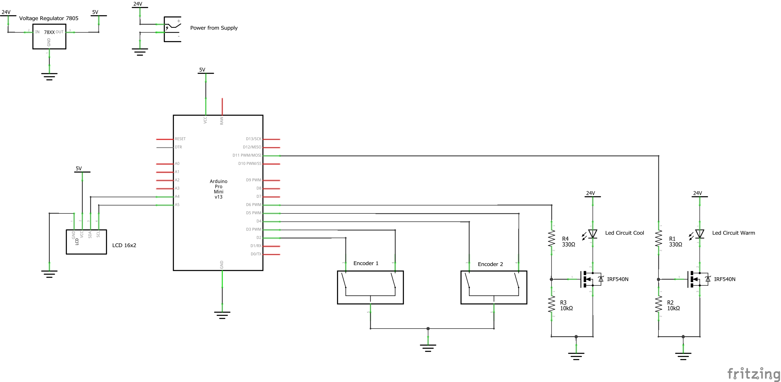
Note that this schematic is the one present in the device with the aforementioned encoder pin issue: pin 2,3 ->Encoder 1 and pin 4,5 ->Encoder 2, where 1 encoder gets both interrupt pins while the other gets none. This is also noted in the device code and concluding thoughts, so anyone aiming to reproduce at least the encoder part of the design should take note of it in both their electrical and software components.
Design Files:
Comments are closed.