Overview
This device helps the user develop habits by allowing the user to track the strength of habits via RFID tags. Each time the user performs an activity, they can scan the associated RFID tag/key card on the device as a tally of how many times they’ve performed the activity. When this happens a certain amount of time, the activity is considered a developed habit.
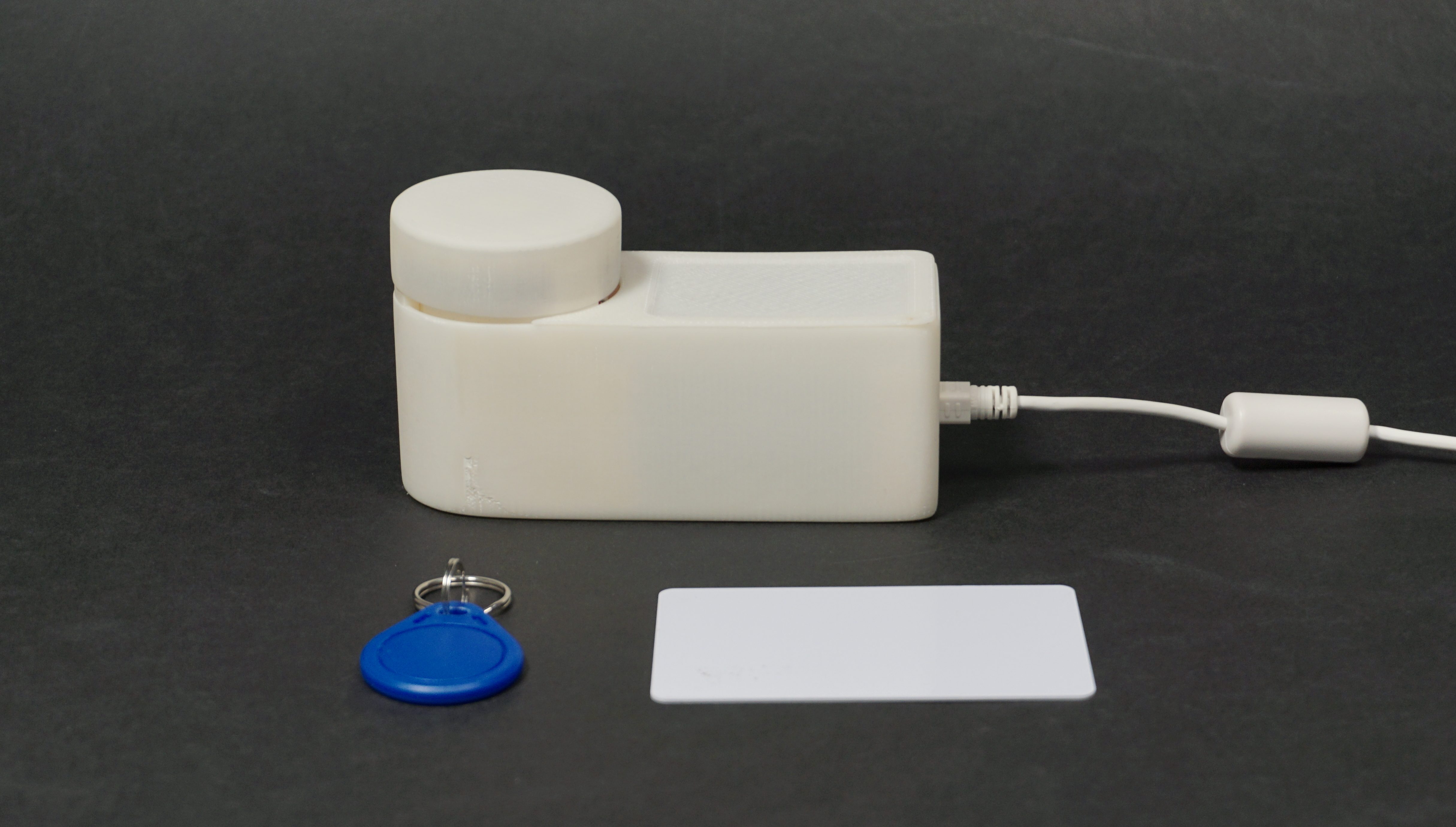
Front view of the device with two types of compatible RFID-embedded objects.
Usage Demo
Details
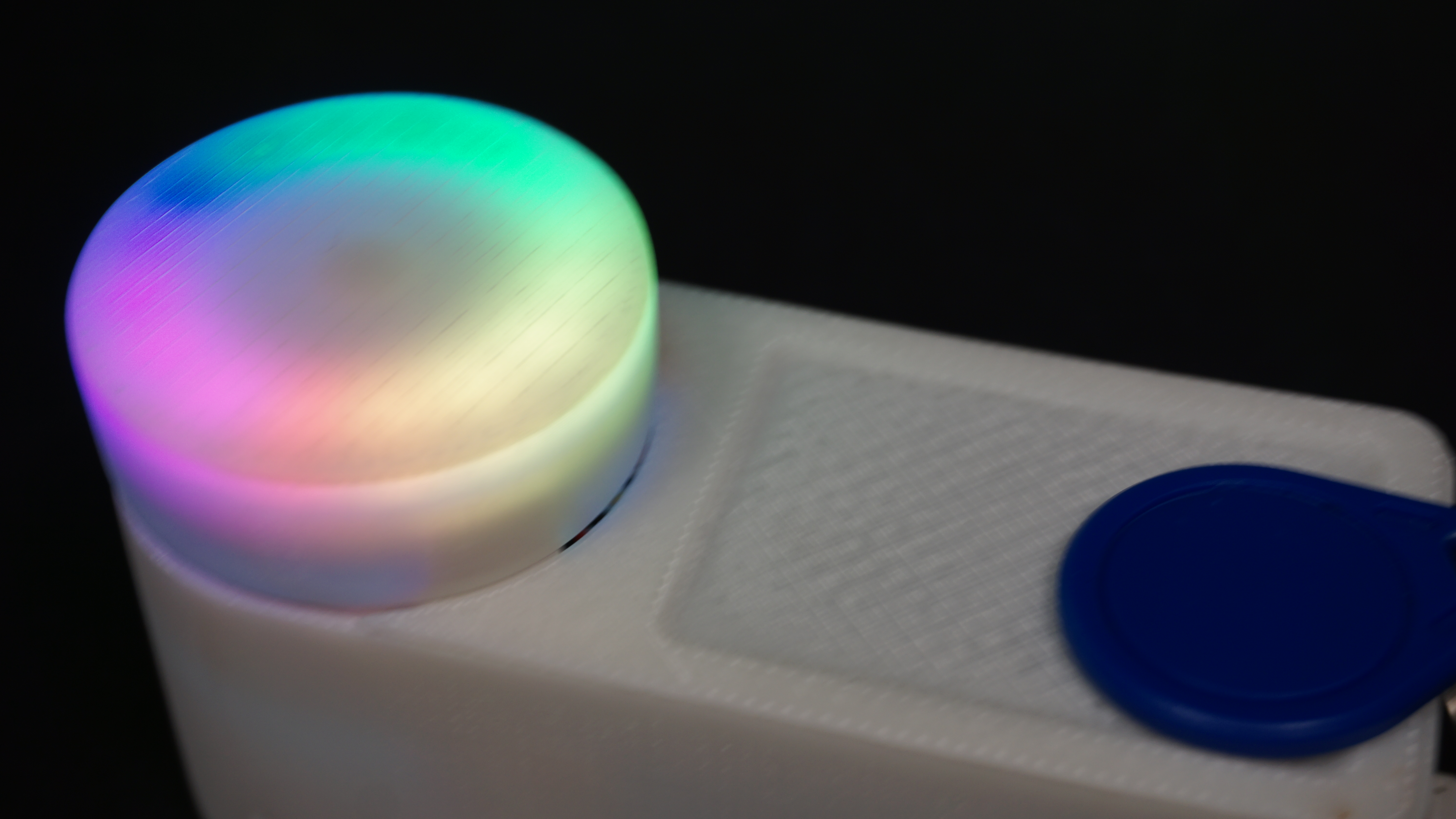
A fully “developed” habit will trigger the light ring embedded within the dial to display a rainbow.
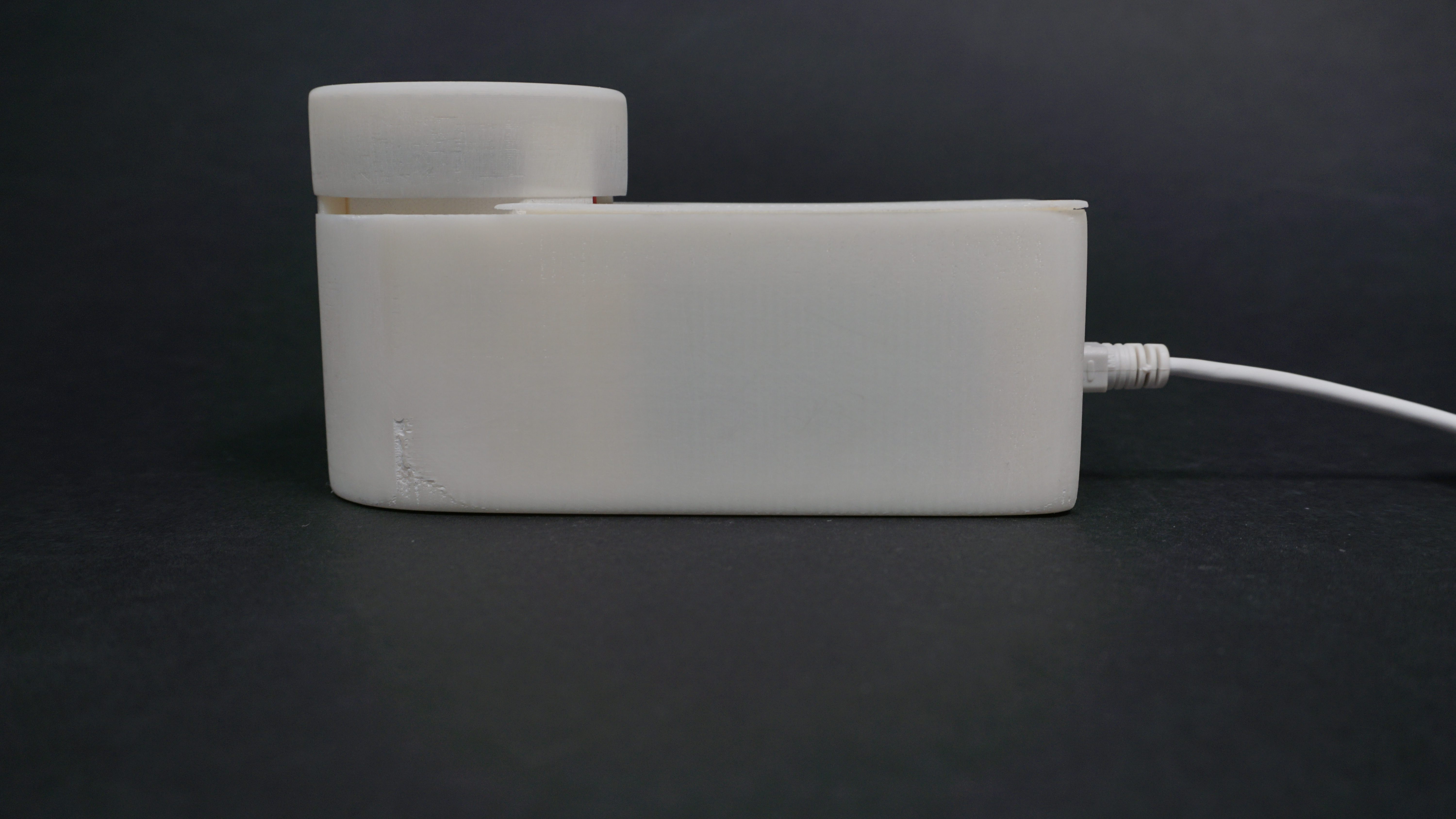
Front view of device showing the size of the dial and scanning surface
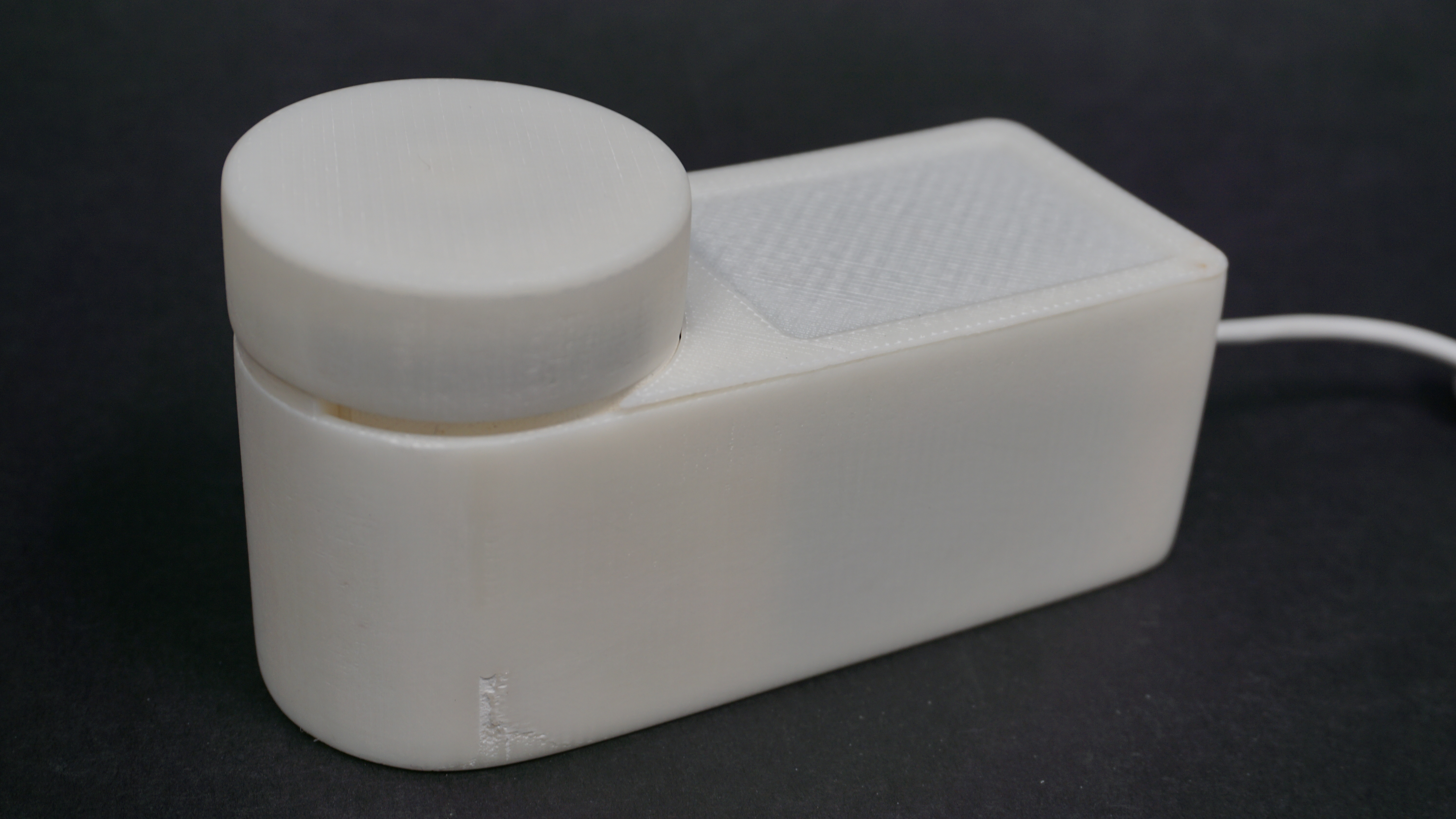
The interface of the device is a cylindrical dial with an embedded button and LED ring, as well as a RFID reader underneath the flat surface.
Process
The first decision point came from an aesthetic standpoint and occurred early on in the process. My original idea was using a potentiometer to adjust the strength of a habit, and have an LED strip near the RFID scanner to display the strength.
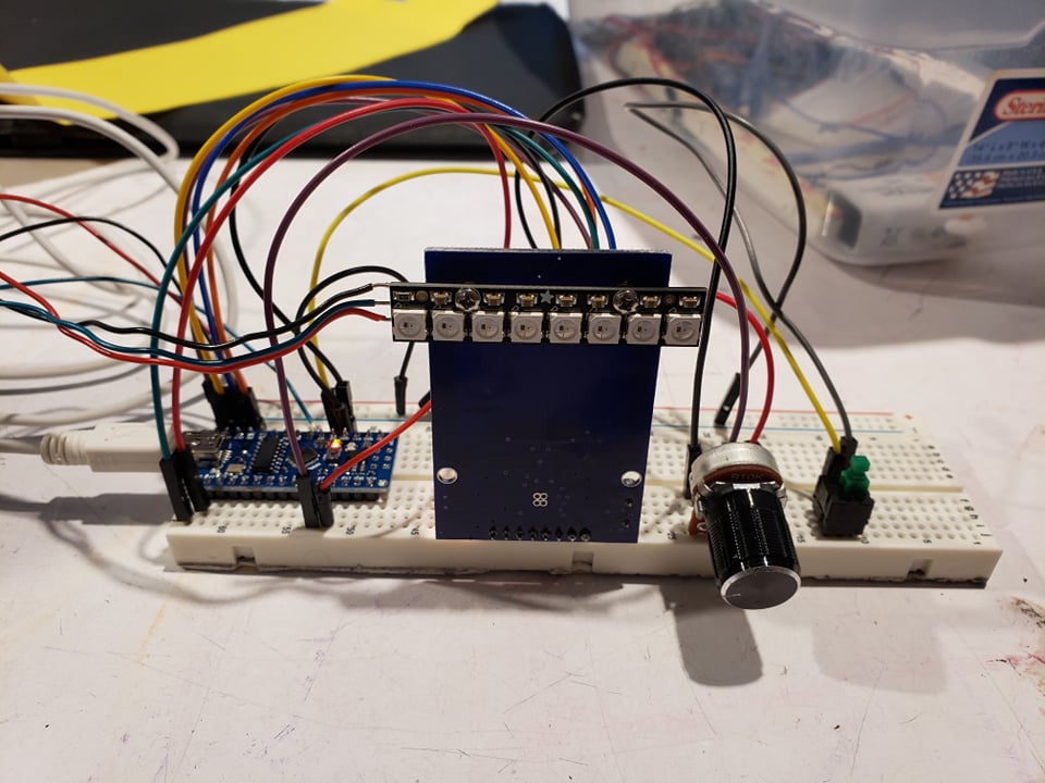
Original proof of concept with a potentiometer, linear Neopixel strip, and separate button.
However, I decided to move to a ring and encoder setup because the LED also needs to be responsive to dial adjustments. By using a ring, the motion of the rotation is coupled with the “motion” of the LED lights. Furthermore, using an encoder allows the user to turn the dial freely, but figuring out what the rotations are translated to is relegated to software.
Though this appeared to be a minor change, the encoder required major restructure of the main program loop. Originally, I wanted to check if a RFID tag is detected by the scanner every cycle. But the time this takes interferes with the encoder’s ability to detect rotation. This led me to introduce a “time out” system for setting a new tag’s strength. Pushing down the encoder while rotating will set the strength, and after releasing the encoder, the user has three seconds to flash a new tag. Otherwise, the nano goes back to waiting to read a tag.
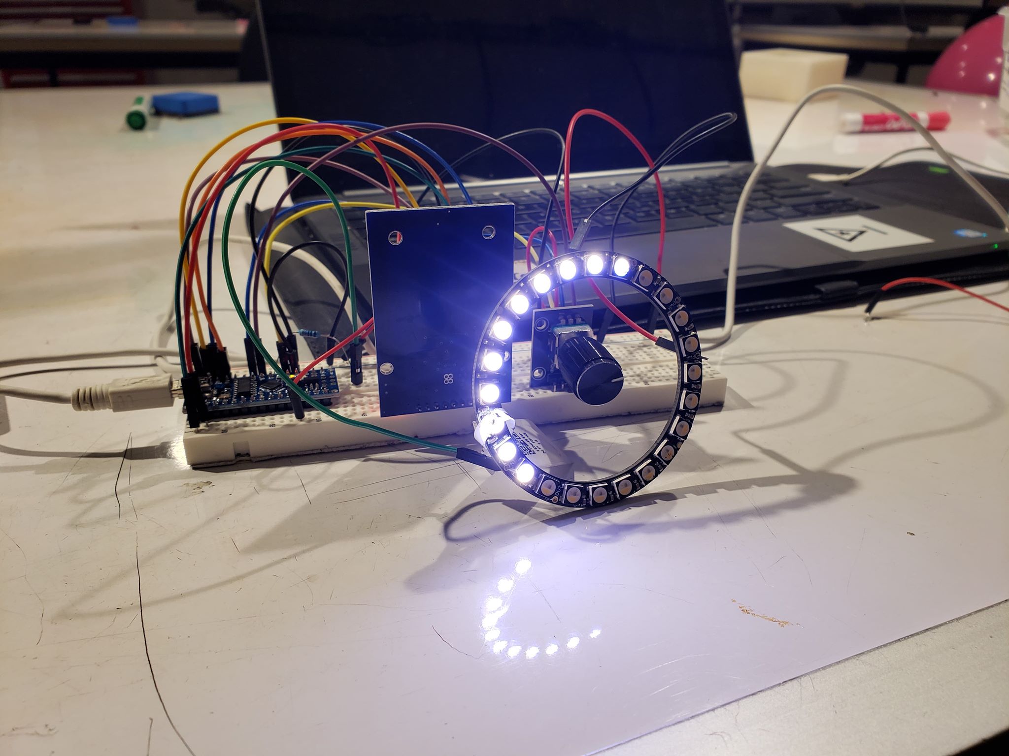
Converting to Neopixel ring and rotary encoder with built-in button.
One feature I wanted to add was making time a factor in the calculation of how strong a strength is. However, I decided against implementing it. Because of the long-running nature of this device, I would need to incorporate timing in the form of an extra component to connect to the arduino. Furthermore, this information would need to be encoded onto the RFID tags. Though this would allow me to differentiate habits I infrequently follow from the ones that I do abide by daily, the amount of technical complications was too much for the time frame of this project.
Instead, after implementing the functions I initially planned on, I decided to focus on designing the appearance of the final product.
Process Highlights
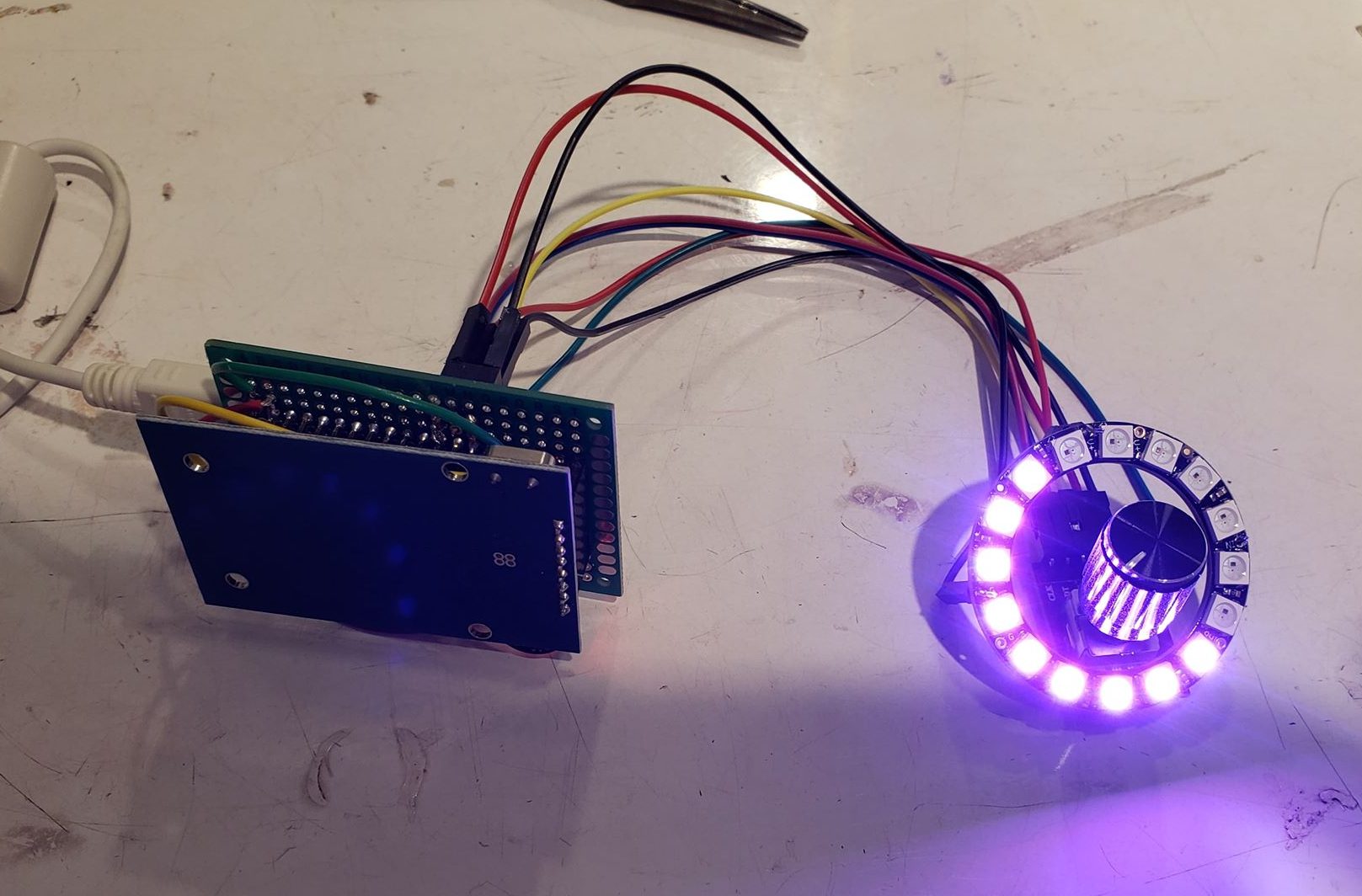
Moving components to a protoboard to slim down the form factor.
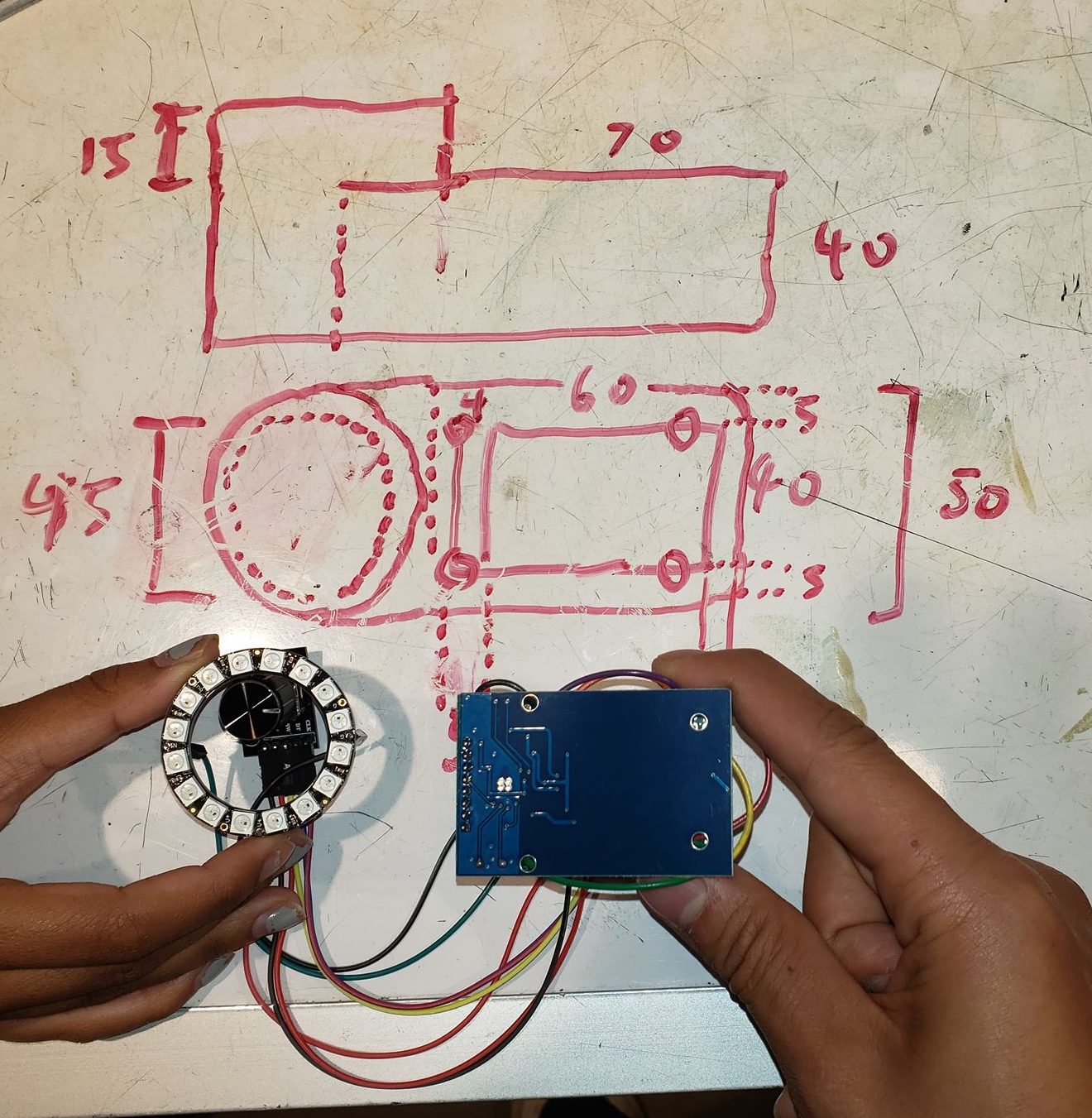
Initial sketch of the enclosure
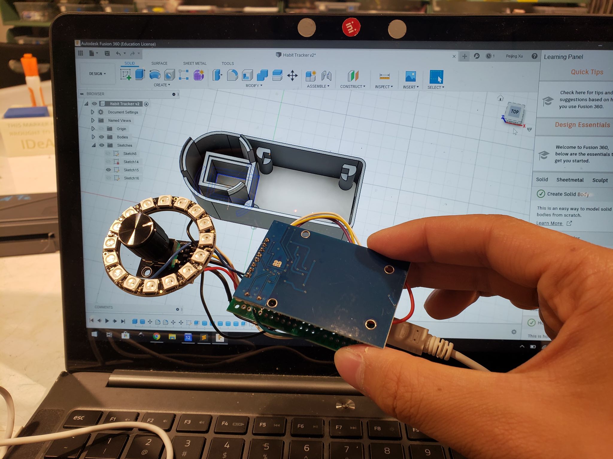
Modeled enclosure with built-in supports for the components.
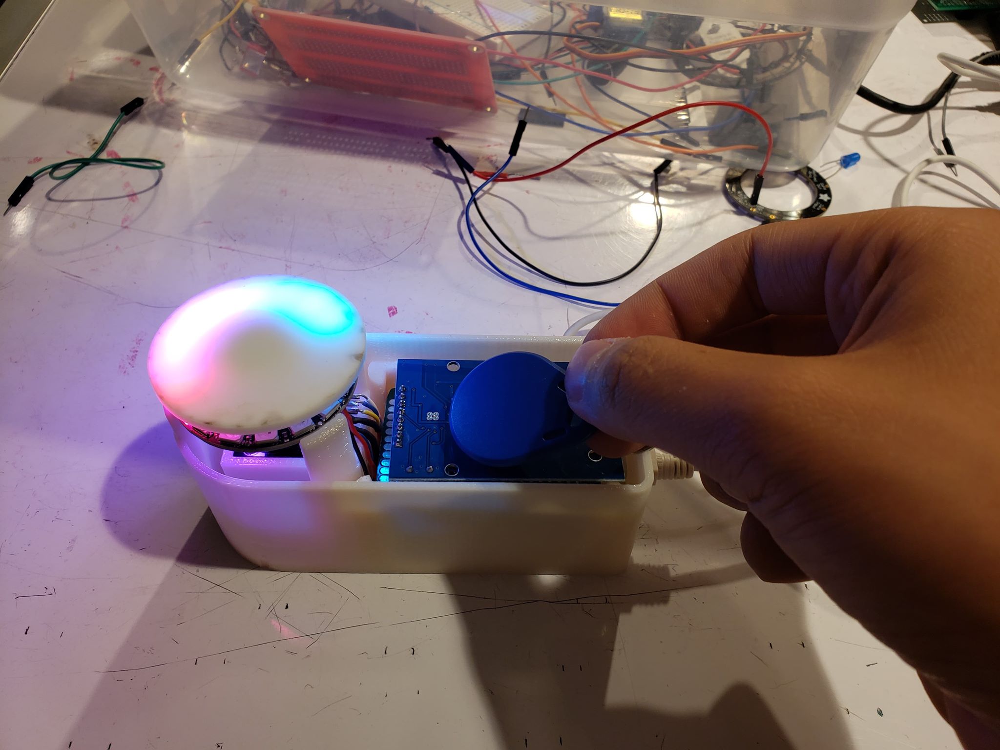
Printed enclosure with placeholder acrylic dial.
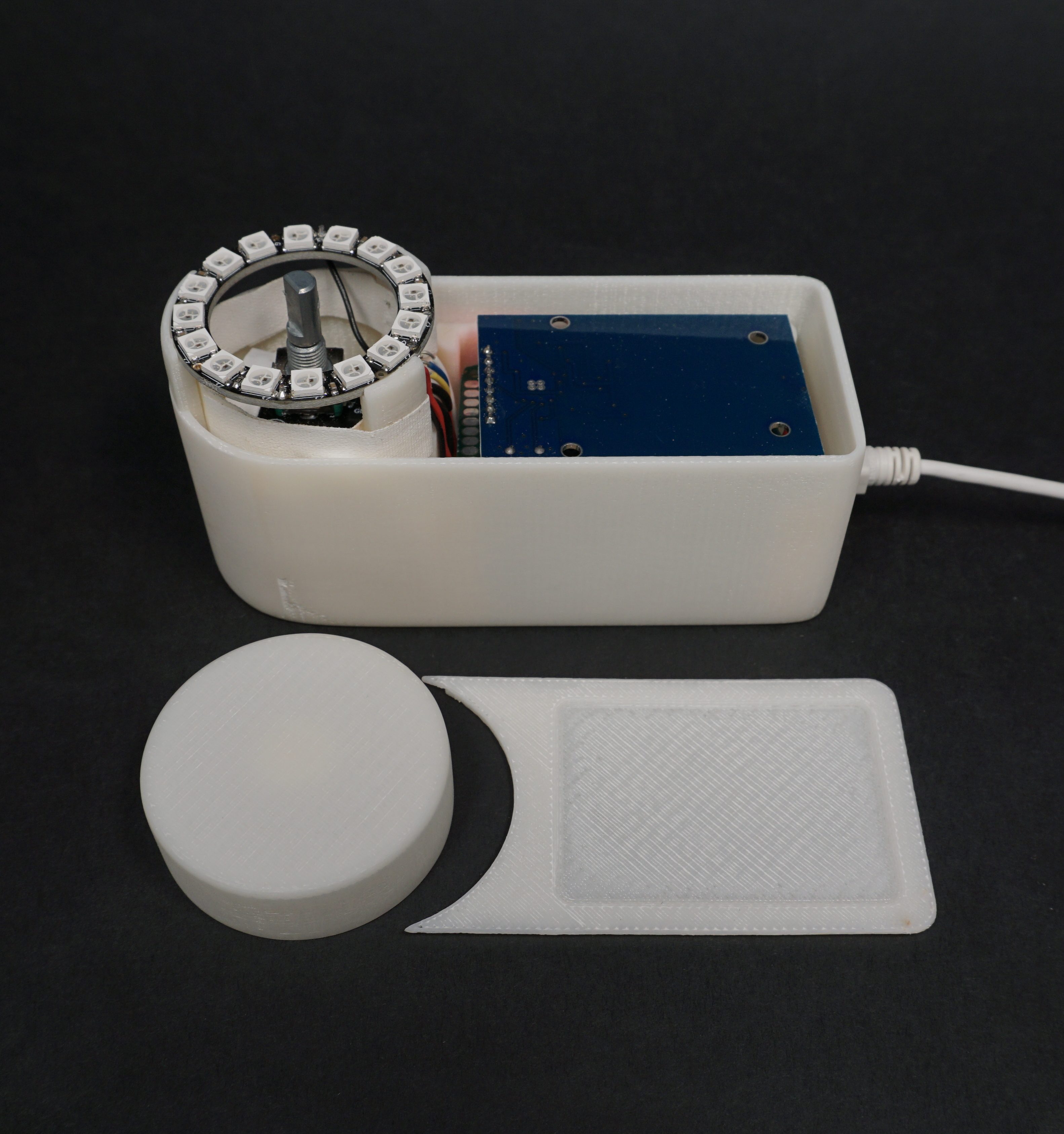
Final enclosure with printed lid and dial.
Discussion
Responses
“A time interval could make it even better.”
The most common points raised during the critique was a lack of a time element. The “strength” of a habit should account for the frequency in which an activity is performed, but my device currently only tracks the amount of times it has been scanned. This is definitely a feature I would like to incorporate, including a way to set the target frequency (e.g. X times/ week). One concern for adding this feature is that it might require a more complicated interface. The consensus seems to be that my current press-and-turn interface is “simple and intuitive.” The simplicity may come from the fact that there is only one thing to control right now: the maximum number of times the tag is scanned to fill up the light ring. If there are two degrees of freedom involved, I would need to think of a way for one dial to set two parameters.
Another way I could maintain the simplicity of the interface is to set a constant number/duration for which a tag must be scanned. However, the dial will then only set the desired frequency, using this and the actual frequency of scanning to calculate “strength”.
“I wonder if there could be the opposite, where it punishes you for having bad habits.”
If this time feature is implemented, I could introduce a decay factor into my habit. This way, the strength of the habit could decrease if the scanning becomes too infrequent. Although this is not necessarily a real punishment, it does mean that I will be further from getting to see the rainbow lights spin around.
Another question raised during the critique was how I will remember to scan the tags related to an activity when I am not immediately next to my desk, which is where this device would be. An example I provided is putting a tag on my gym bag, so when I come home from the gym I will naturally scan it. However, not every activity may have a physical object associated with it, which would make remembering more difficult. The hope would then be that seeing this tracker on my desk can also serve as a reminder for me to perform tasks as well as remember to scan tags associated with them. In that sense, remembering to use this device is also a habit I would then need to develop.
Self Critique and Takeaways
Looking back, I think that this project was quite ambitious given that it was an individual project over the course of two weeks. I am happy with the way that my project turned out, but I also think I could have been more ambitious. I decided to focus on the physical design of my project over the software because I wanted to use this assignment as a way to explore that field. Because of this, I settled with a conceptually simple (but still challenging to implement) software side.
One of the potential issues on the software side I decided to overlook was the sequential nature of the LED animations. Because each animation routine was a separate function that used delay() for timing, no RFID tags will be scanned when an animation is being played. This also means that tags must be scanned one at a time, i.e. I would not be able to bulk scan a lot of tags (e.g. at the end of the say when I get home). However, an advantage of this is that I would be able to see the status of each tag I scan, which would can serve as a way for me to check in with myself about a habit and give enough time for all of them.
I wanted to learn how to design and 3D print for this project, and I was able to accomplish that goal. Translating something from my mind to the whiteboard, then to a modeling software, and finally materialized in physical space was a very exciting process for me, and I learned to consider a lot of different factors in my design, especially the space required to fit components. For example, the wiring for the neopixel needed to be routed through the dial to the protoboard, so I needed to make sure that there was enough clearance between the encoder stand and the protoboard stand to route these wires. While designing the internal components, I also had a general idea of how I wanted the external appearance would turn out, and this also helped the final design come together.
Nonetheless, there were also some issues with my 3D printed enclosure, which is understandable for my first time designing. The stands for my protoboard were too small, so I needed to sand down the edges of the board for it to fit. On the other hand, the stand for the encoder was too wide for the component to sit snugly in it. I used tape make sure it stayed in its place during operation. Moreover, I made the dial a bit too flimsy because the sides of it were too thin, and this made turning the dial feel less stable than anticipated. Another detail I overlooked was the gap between the dial and the body of the enclosure. The gap is inevitable, as there needs to be room for the dial to be pressed. However, this exposed the internals originally, and I improvised by wrapping the central LED ring support with white tape.
I learn a lot about my own process for designing, which involved quite a bit of improvising. After all, this is only the first iteration. I wanted to make sure that my internal components worked before I began to think too much about the final “look” of the product. I seem to allow the functionalities and components to dictate the form, instead of the other way around. I also designed the base before I designed the dial and top cover because I needed a tangible product to test fit the internals. Some of the considerations about the base only arose when the dial and lid needed to be designed, but it was too late. To summarize, I think I take on a very impatient but incremental approach to design, which caused some unfortunately silly mistakes.
What’s Next?
In the next iteration, I would address some of the issues with the external enclosure (i.e. make the dial sturdier, adjust the supports for components). Since this device would be sitting on my desk, I could afford to make it larger to fit in a real time clock module, which would allow me to implement the time-based features discussed above.
Another potential addition could be a way to report the development of a habit over time, like a line chart. This could be done via IoT method (most likely an AWS or Google Cloud micro service), so I could have a web dashboard that keeps track of my habit development. Another more analog way could be using a dot matrix printer. It could be a slow process where, after each day, a single line is printed, with each dot corresponding to a habit. There are a lot of directions this project could take, and I am excited to see what direction I end up choosing.
Technical Information
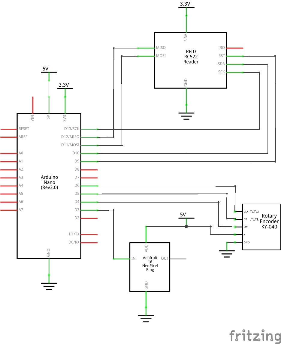
Schematic
Code
- <span class="com">/*
- RFID Habit Tracker
- This is the code for the Arduino Nano Rev3 board within the habit tracker.
- Each time an RFID chip is scanned by the MFRC522 unit,
- a byte stored within the chip (buffer[0]) is incremented
- in its memory block (buffer) to represent the number of times a habit is reinforced.
- The maximum limit to increment up until is set by turning the encoder while
- pressing it down, and "flashing" a new tag with buffer[1] set as the
- max count.
- The status of a habit, when incremented, is displayed on the Neopixel ring with an animation.
- When turning the rotary encoder, the strength is also represented on the ring.
- When a tag has been scanned its "maximum" times, the ring fills up and rotates.
- The Adafruit Neopixel API was consulted to implement the LED animations.
- (https://learn.adafruit.com/adafruit-neopixel-uberguide/arduino-library-use)
- The Rotary encoder code is based on the example found here:
- (https://github.com/PaulStoffregen/Encoder)
- The MFRC522 scanner uses the library in the link below.
- (https://github.com/miguelbalboa/rfid)
- MFRC522 Wiring
- -------------------------------
- MFRC522 Arduino
- Reader/PCD Nano v3
- Signal Pin Pin
- -------------------------------
- RST/Reset RST D9
- SPI SS SDA(SS) D10
- SPI MOSI MOSI D11
- SPI MISO MISO D12
- SPI SCK SCK D13
- Other connections
- -----------------------------------
- Device Dev. Pin Arduino Pin
- -----------------------------------
- Neopixel Digital_in D3
- Encoder CLK D6
- Encoder DT D5
- Encoder SW D4
- */</span><span class="pln">
- </span><span class="com">//#define ENCODER_DO_NOT_USE_INTERRUPTS</span><span class="pln">
- </span><span class="com">#include</span><span class="pln"> </span><span class="str"><SPI.h></span><span class="pln">
- </span><span class="com">#include</span><span class="pln"> </span><span class="str"><MFRC522.h></span><span class="pln">
- </span><span class="com">#include</span><span class="pln"> </span><span class="str"><Adafruit_NeoPixel.h></span><span class="pln">
- </span><span class="com">#include</span><span class="pln"> </span><span class="str"><Encoder.h></span><span class="pln">
- </span><span class="com">#ifdef</span><span class="pln"> __AVR__
- </span><span class="com">#include</span><span class="pln"> </span><span class="str"><avr/power.h></span><span class="pln"> </span><span class="com">// Required for 16 MHz Adafruit Trinket</span><span class="pln">
- </span><span class="com">#endif</span><span class="pln">
- </span><span class="kwd">const</span><span class="pln"> </span><span class="kwd">int</span><span class="pln"> RST_PIN </span><span class="pun">=</span><span class="pln"> </span><span class="lit">9</span><span class="pun">;</span><span class="pln">
- </span><span class="kwd">const</span><span class="pln"> </span><span class="kwd">int</span><span class="pln"> SS_PIN </span><span class="pun">=</span><span class="pln"> </span><span class="lit">10</span><span class="pun">;</span><span class="pln">
- </span><span class="kwd">const</span><span class="pln"> </span><span class="kwd">int</span><span class="pln"> LED_PIN </span><span class="pun">=</span><span class="pln"> </span><span class="lit">3</span><span class="pun">;</span><span class="pln">
- </span><span class="kwd">const</span><span class="pln"> </span><span class="kwd">int</span><span class="pln"> BUTTON_PIN </span><span class="pun">=</span><span class="pln"> </span><span class="lit">4</span><span class="pun">;</span><span class="pln">
- </span><span class="com">// milliseconds of no button press until we stop waiting to "flash"</span><span class="pln">
- </span><span class="kwd">const</span><span class="pln"> </span><span class="kwd">int</span><span class="pln"> TIMEOUT </span><span class="pun">=</span><span class="pln"> </span><span class="lit">3000</span><span class="pun">;</span><span class="pln">
- </span><span class="com">//Max val the encoder can take on</span><span class="pln">
- </span><span class="kwd">const</span><span class="pln"> </span><span class="kwd">int</span><span class="pln"> MAX_ENCODER </span><span class="pun">=</span><span class="pln"> </span><span class="lit">100</span><span class="pun">;</span><span class="pln">
- </span><span class="com">//Max val that buffer[1] could be</span><span class="pln">
- </span><span class="kwd">const</span><span class="pln"> </span><span class="kwd">int</span><span class="pln"> MAX_SCANS </span><span class="pun">=</span><span class="pln"> </span><span class="lit">30</span><span class="pln">
- </span><span class="kwd">const</span><span class="pln"> </span><span class="kwd">int</span><span class="pln"> LED_COUNT </span><span class="pun">=</span><span class="pln"> </span><span class="lit">16</span><span class="pun">;</span><span class="pln">
- </span><span class="kwd">const</span><span class="pln"> </span><span class="kwd">int</span><span class="pln"> BRIGHTNESS </span><span class="pun">=</span><span class="pln"> </span><span class="lit">100</span><span class="pun">;</span><span class="pln">
- </span><span class="kwd">const</span><span class="pln"> </span><span class="kwd">int</span><span class="pln"> FILLUP_SPEED </span><span class="pun">=</span><span class="pln"> </span><span class="lit">10</span><span class="pun">;</span><span class="pln">
- </span><span class="com">//Location of bytes in the RFID tag to write to</span><span class="pln">
- </span><span class="kwd">const</span><span class="pln"> </span><span class="kwd">byte</span><span class="pln"> BLK_ADDR </span><span class="pun">=</span><span class="pln"> </span><span class="lit">4</span><span class="pun">;</span><span class="pln">
- </span><span class="kwd">const</span><span class="pln"> </span><span class="kwd">byte</span><span class="pln"> TRAILER_BLK </span><span class="pun">=</span><span class="pln"> </span><span class="lit">7</span><span class="pun">;</span><span class="pln">
- </span><span class="kwd">float</span><span class="pln"> </span><span class="kwd">last</span><span class="pln"> </span><span class="pun">=</span><span class="pln"> millis</span><span class="pun">();</span><span class="pln">
- </span><span class="kwd">long</span><span class="pln"> pos </span><span class="pun">=</span><span class="pln"> </span><span class="lit">0</span><span class="pun">;</span><span class="pln">
- </span><span class="kwd">bool</span><span class="pln"> increment</span><span class="pun">;</span><span class="pln">
- </span><span class="com">// Declare NeoPixel strip object:</span><span class="pln">
- </span><span class="typ">Adafruit_NeoPixel</span><span class="pln"> strip</span><span class="pun">(</span><span class="pln">LED_COUNT</span><span class="pun">,</span><span class="pln"> LED_PIN</span><span class="pun">,</span><span class="pln"> NEO_GRB </span><span class="pun">+</span><span class="pln"> NEO_KHZ800</span><span class="pun">);</span><span class="pln">
- </span><span class="com">// Create MFRC522 instance.</span><span class="pln">
- MFRC522 mfrc522</span><span class="pun">(</span><span class="pln">SS_PIN</span><span class="pun">,</span><span class="pln"> RST_PIN</span><span class="pun">);</span><span class="pln">
- MFRC522</span><span class="pun">::</span><span class="pln">MIFARE_Key key</span><span class="pun">;</span><span class="pln">
- </span><span class="typ">Encoder</span><span class="pln"> myEnc</span><span class="pun">(</span><span class="lit">6</span><span class="pun">,</span><span class="pln"> </span><span class="lit">5</span><span class="pun">);</span><span class="pln">
- </span><span class="kwd">void</span><span class="pln"> dump_byte_array</span><span class="pun">(</span><span class="kwd">byte</span><span class="pln"> </span><span class="pun">*</span><span class="pln">buffer</span><span class="pun">,</span><span class="pln"> </span><span class="kwd">byte</span><span class="pln"> bufferSize</span><span class="pun">);</span><span class="pln">
- </span><span class="kwd">void</span><span class="pln"> setup</span><span class="pun">()</span><span class="pln"> </span><span class="pun">{</span><span class="pln">
- </span><span class="typ">Serial</span><span class="pun">.</span><span class="kwd">begin</span><span class="pun">(</span><span class="lit">115200</span><span class="pun">);</span><span class="pln"> </span><span class="com">// Initialize serial communications with the PC</span><span class="pln">
- pinMode</span><span class="pun">(</span><span class="pln">BUTTON_PIN</span><span class="pun">,</span><span class="pln"> INPUT_PULLUP</span><span class="pun">);</span><span class="pln">
- strip</span><span class="pun">.</span><span class="kwd">begin</span><span class="pun">();</span><span class="pln"> </span><span class="com">// INITIALIZE NeoPixel strip object (REQUIRED)</span><span class="pln">
- strip</span><span class="pun">.</span><span class="pln">show</span><span class="pun">();</span><span class="pln"> </span><span class="com">// Turn OFF all pixels ASAP</span><span class="pln">
- strip</span><span class="pun">.</span><span class="pln">setBrightness</span><span class="pun">(</span><span class="pln">BRIGHTNESS</span><span class="pun">);</span><span class="pln"> </span><span class="com">// Set BRIGHTNESS to about 1/5 (max = 255)</span><span class="pln">
- SPI</span><span class="pun">.</span><span class="kwd">begin</span><span class="pun">();</span><span class="pln"> </span><span class="com">// Init SPI bus</span><span class="pln">
- mfrc522</span><span class="pun">.</span><span class="pln">PCD_Init</span><span class="pun">();</span><span class="pln"> </span><span class="com">// Init MFRC522 card</span><span class="pln">
- </span><span class="com">// Prepare the key (used both as key A and as key B)</span><span class="pln">
- </span><span class="kwd">for</span><span class="pln"> </span><span class="pun">(</span><span class="kwd">byte</span><span class="pln"> i </span><span class="pun">=</span><span class="pln"> </span><span class="lit">0</span><span class="pun">;</span><span class="pln"> i </span><span class="pun"><</span><span class="pln"> </span><span class="lit">6</span><span class="pun">;</span><span class="pln"> i</span><span class="pun">++)</span><span class="pln"> </span><span class="pun">{</span><span class="pln">
- key</span><span class="pun">.</span><span class="pln">keyByte</span><span class="pun">[</span><span class="pln">i</span><span class="pun">]</span><span class="pln"> </span><span class="pun">=</span><span class="pln"> </span><span class="lit">0xFF</span><span class="pun">;</span><span class="pln">
- </span><span class="pun">}</span><span class="pln">
- </span><span class="pun">}</span><span class="pln">
- </span><span class="com">/*
- Main loop.
- */</span><span class="pln">
- </span><span class="kwd">void</span><span class="pln"> loop</span><span class="pun">()</span><span class="pln"> </span><span class="pun">{</span><span class="pln">
- </span><span class="kwd">bool</span><span class="pln"> button </span><span class="pun">=</span><span class="pln"> </span><span class="pun">!</span><span class="pln">digitalRead</span><span class="pun">(</span><span class="pln">BUTTON_PIN</span><span class="pun">);</span><span class="pln">
- </span><span class="kwd">bool</span><span class="pln"> flashed </span><span class="pun">=</span><span class="pln"> </span><span class="kwd">false</span><span class="pun">;</span><span class="pln">
- </span><span class="kwd">if</span><span class="pln"> </span><span class="pun">(</span><span class="pln">button</span><span class="pun">)</span><span class="pln"> </span><span class="pun">{</span><span class="pln">
- increment </span><span class="pun">=</span><span class="pln"> </span><span class="kwd">false</span><span class="pun">;</span><span class="pln">
- </span><span class="kwd">last</span><span class="pln"> </span><span class="pun">=</span><span class="pln"> millis</span><span class="pun">();</span><span class="pln">
- pos </span><span class="pun">=</span><span class="pln"> min</span><span class="pun">(</span><span class="pln">max</span><span class="pun">(</span><span class="lit">0</span><span class="pun">,</span><span class="pln"> myEnc</span><span class="pun">.</span><span class="pln">read</span><span class="pun">()),</span><span class="pln"> MAX_ENCODER</span><span class="pun">);</span><span class="pln">
- myEnc</span><span class="pun">.</span><span class="pln">write</span><span class="pun">(</span><span class="pln">pos</span><span class="pun">);</span><span class="pln">
- display</span><span class="pun">(</span><span class="pln">pos</span><span class="pun">,</span><span class="pln"> MAX_ENCODER</span><span class="pun">);</span><span class="pln">
- </span><span class="kwd">return</span><span class="pun">;</span><span class="pln">
- </span><span class="pun">}</span><span class="pln"> </span><span class="kwd">else</span><span class="pln"> </span><span class="pun">{</span><span class="pln">
- </span><span class="com">// "flash" routine timed out, go back to waiting to</span><span class="pln">
- </span><span class="com">// read and increment RFID tag</span><span class="pln">
- </span><span class="kwd">if</span><span class="pln"> </span><span class="pun">(</span><span class="pln">millis</span><span class="pun">()</span><span class="pln"> </span><span class="pun">-</span><span class="pln"> </span><span class="kwd">last</span><span class="pln"> </span><span class="pun">></span><span class="pln"> TIMEOUT</span><span class="pun">)</span><span class="pln"> </span><span class="pun">{</span><span class="pln">
- fadeout</span><span class="pun">(</span><span class="lit">2</span><span class="pun">);</span><span class="pln">
- increment </span><span class="pun">=</span><span class="pln"> </span><span class="kwd">true</span><span class="pun">;</span><span class="pln">
- myEnc</span><span class="pun">.</span><span class="pln">write</span><span class="pun">(</span><span class="lit">0</span><span class="pun">);</span><span class="pln">
- </span><span class="pun">}</span><span class="pln">
- </span><span class="pun">}</span><span class="pln">
- </span><span class="com">// Reset the loop if no new card present on the sensor/reader.</span><span class="pln">
- </span><span class="com">// We only check rfid tags when the button is not pressed</span><span class="pln">
- </span><span class="com">// This prevents encoder lagging</span><span class="pln">
- </span><span class="kwd">if</span><span class="pln"> </span><span class="pun">(</span><span class="pln"> </span><span class="pun">!</span><span class="pln"> mfrc522</span><span class="pun">.</span><span class="pln">PICC_IsNewCardPresent</span><span class="pun">())</span><span class="pln"> </span><span class="pun">{</span><span class="pln">
- </span><span class="kwd">return</span><span class="pun">;</span><span class="pln">
- </span><span class="pun">}</span><span class="pln">
- </span><span class="com">// Select one of the cards</span><span class="pln">
- </span><span class="kwd">if</span><span class="pln"> </span><span class="pun">(</span><span class="pln"> </span><span class="pun">!</span><span class="pln"> mfrc522</span><span class="pun">.</span><span class="pln">PICC_ReadCardSerial</span><span class="pun">())</span><span class="pln">
- </span><span class="kwd">return</span><span class="pun">;</span><span class="pln">
- </span><span class="com">//reset encoder position</span><span class="pln">
- myEnc</span><span class="pun">.</span><span class="pln">write</span><span class="pun">(</span><span class="lit">0</span><span class="pun">);</span><span class="pln">
- </span><span class="com">//declare buffer for data to be read into</span><span class="pln">
- MFRC522</span><span class="pun">::</span><span class="typ">StatusCode</span><span class="pln"> status</span><span class="pun">;</span><span class="pln">
- </span><span class="kwd">byte</span><span class="pln"> buffer</span><span class="pun">[</span><span class="lit">18</span><span class="pun">];</span><span class="pln">
- </span><span class="kwd">byte</span><span class="pln"> size </span><span class="pun">=</span><span class="pln"> </span><span class="kwd">sizeof</span><span class="pun">(</span><span class="pln">buffer</span><span class="pun">);</span><span class="pln">
- </span><span class="com">// Authenticate using key A,B</span><span class="pln">
- status </span><span class="pun">=</span><span class="pln"> </span><span class="pun">(</span><span class="pln">MFRC522</span><span class="pun">::</span><span class="typ">StatusCode</span><span class="pun">)</span><span class="pln"> mfrc522</span><span class="pun">.</span><span class="pln">PCD_Authenticate</span><span class="pun">(</span><span class="pln">
- MFRC522</span><span class="pun">::</span><span class="pln">PICC_CMD_MF_AUTH_KEY_A</span><span class="pun">,</span><span class="pln"> TRAILER_BLK</span><span class="pun">,</span><span class="pln"> </span><span class="pun">&</span><span class="pln">key</span><span class="pun">,</span><span class="pln"> </span><span class="pun">&(</span><span class="pln">mfrc522</span><span class="pun">.</span><span class="pln">uid</span><span class="pun">));</span><span class="pln">
- status </span><span class="pun">=</span><span class="pln"> </span><span class="pun">(</span><span class="pln">MFRC522</span><span class="pun">::</span><span class="typ">StatusCode</span><span class="pun">)</span><span class="pln"> mfrc522</span><span class="pun">.</span><span class="pln">PCD_Authenticate</span><span class="pun">(</span><span class="pln">
- MFRC522</span><span class="pun">::</span><span class="pln">PICC_CMD_MF_AUTH_KEY_B</span><span class="pun">,</span><span class="pln"> TRAILER_BLK</span><span class="pun">,</span><span class="pln"> </span><span class="pun">&</span><span class="pln">key</span><span class="pun">,</span><span class="pln"> </span><span class="pun">&(</span><span class="pln">mfrc522</span><span class="pun">.</span><span class="pln">uid</span><span class="pun">));</span><span class="pln">
- </span><span class="kwd">if</span><span class="pln"> </span><span class="pun">(</span><span class="pln">status </span><span class="pun">!=</span><span class="pln"> MFRC522</span><span class="pun">::</span><span class="pln">STATUS_OK</span><span class="pun">)</span><span class="pln"> </span><span class="pun">{</span><span class="pln">
- </span><span class="typ">Serial</span><span class="pun">.</span><span class="kwd">print</span><span class="pun">(</span><span class="pln">F</span><span class="pun">(</span><span class="str">"PCD_Authenticate() failed: "</span><span class="pun">));</span><span class="pln">
- </span><span class="typ">Serial</span><span class="pun">.</span><span class="pln">println</span><span class="pun">(</span><span class="pln">mfrc522</span><span class="pun">.</span><span class="typ">GetStatusCodeName</span><span class="pun">(</span><span class="pln">status</span><span class="pun">));</span><span class="pln">
- </span><span class="kwd">return</span><span class="pun">;</span><span class="pln">
- </span><span class="pun">}</span><span class="pln">
- </span><span class="com">// Read to buffer</span><span class="pln">
- mfrc522</span><span class="pun">.</span><span class="pln">MIFARE_Read</span><span class="pun">(</span><span class="pln">BLK_ADDR</span><span class="pun">,</span><span class="pln"> buffer</span><span class="pun">,</span><span class="pln"> </span><span class="pun">&</span><span class="pln">size</span><span class="pun">);</span><span class="pln">
- </span><span class="com">//Update buffer or reinitialize buffer</span><span class="pln">
- </span><span class="kwd">if</span><span class="pln"> </span><span class="pun">(</span><span class="pln">increment</span><span class="pun">)</span><span class="pln"> </span><span class="pun">{</span><span class="pln">
- buffer</span><span class="pun">[</span><span class="lit">0</span><span class="pun">]</span><span class="pln"> </span><span class="pun">=</span><span class="pln"> min</span><span class="pun">(</span><span class="pln">buffer</span><span class="pun">[</span><span class="lit">0</span><span class="pun">]</span><span class="pln"> </span><span class="pun">+</span><span class="pln"> </span><span class="lit">1</span><span class="pun">,</span><span class="pln"> buffer</span><span class="pun">[</span><span class="lit">1</span><span class="pun">]);</span><span class="pln">
- </span><span class="pun">}</span><span class="pln"> </span><span class="kwd">else</span><span class="pln"> </span><span class="pun">{</span><span class="pln">
- increment </span><span class="pun">=</span><span class="pln"> </span><span class="kwd">true</span><span class="pun">;</span><span class="pln">
- flashed </span><span class="pun">=</span><span class="pln"> </span><span class="kwd">true</span><span class="pun">;</span><span class="pln">
- buffer</span><span class="pun">[</span><span class="lit">0</span><span class="pun">]</span><span class="pln"> </span><span class="pun">=</span><span class="pln"> </span><span class="lit">0</span><span class="pun">;</span><span class="pln">
- buffer</span><span class="pun">[</span><span class="lit">1</span><span class="pun">]</span><span class="pln"> </span><span class="pun">=</span><span class="pln"> map</span><span class="pun">(</span><span class="pln">pos</span><span class="pun">,</span><span class="pln"> </span><span class="lit">0</span><span class="pun">,</span><span class="pln"> MAX_ENCODER</span><span class="pun">,</span><span class="pln"> </span><span class="lit">0</span><span class="pun">,</span><span class="pln"> MAX_SCANS</span><span class="pun">);</span><span class="pln">
- </span><span class="pun">}</span><span class="pln">
- </span><span class="com">// Write data to the block</span><span class="pln">
- status </span><span class="pun">=</span><span class="pln"> </span><span class="pun">(</span><span class="pln">MFRC522</span><span class="pun">::</span><span class="typ">StatusCode</span><span class="pun">)</span><span class="pln"> mfrc522</span><span class="pun">.</span><span class="pln">MIFARE_Write</span><span class="pun">(</span><span class="pln">BLK_ADDR</span><span class="pun">,</span><span class="pln"> buffer</span><span class="pun">,</span><span class="pln"> </span><span class="lit">16</span><span class="pun">);</span><span class="pln">
- </span><span class="kwd">if</span><span class="pln"> </span><span class="pun">(</span><span class="pln">status </span><span class="pun">!=</span><span class="pln"> MFRC522</span><span class="pun">::</span><span class="pln">STATUS_OK</span><span class="pun">)</span><span class="pln"> </span><span class="pun">{</span><span class="pln">
- </span><span class="typ">Serial</span><span class="pun">.</span><span class="kwd">print</span><span class="pun">(</span><span class="pln">F</span><span class="pun">(</span><span class="str">"MIFARE_Write() failed: "</span><span class="pun">));</span><span class="pln">
- </span><span class="typ">Serial</span><span class="pun">.</span><span class="pln">println</span><span class="pun">(</span><span class="pln">mfrc522</span><span class="pun">.</span><span class="typ">GetStatusCodeName</span><span class="pun">(</span><span class="pln">status</span><span class="pun">));</span><span class="pln">
- </span><span class="pun">}</span><span class="pln">
- </span><span class="com">// Halt PICC</span><span class="pln">
- mfrc522</span><span class="pun">.</span><span class="pln">PICC_HaltA</span><span class="pun">();</span><span class="pln">
- </span><span class="com">// Stop encryption on PCD</span><span class="pln">
- mfrc522</span><span class="pun">.</span><span class="pln">PCD_StopCrypto1</span><span class="pun">();</span><span class="pln">
- </span><span class="com">// fill up ring and fade out to indicate newly flashed tag</span><span class="pln">
- </span><span class="kwd">if</span><span class="pln"> </span><span class="pun">(</span><span class="pln">flashed</span><span class="pun">)</span><span class="pln"> </span><span class="pun">{</span><span class="pln">
- </span><span class="kwd">for</span><span class="pln"> </span><span class="pun">(</span><span class="kwd">int</span><span class="pln"> i </span><span class="pun">=</span><span class="pln"> pos</span><span class="pun">;</span><span class="pln"> i </span><span class="pun"><</span><span class="pln"> MAX_ENCODER</span><span class="pun">;</span><span class="pln"> i</span><span class="pun">++)</span><span class="pln"> </span><span class="pun">{</span><span class="pln">
- display</span><span class="pun">(</span><span class="pln">i</span><span class="pun">,</span><span class="pln"> MAX_ENCODER</span><span class="pun">);</span><span class="pln">
- delay</span><span class="pun">(</span><span class="lit">3</span><span class="pun">);</span><span class="pln">
- </span><span class="pun">}</span><span class="pln">
- fadeout</span><span class="pun">(</span><span class="lit">1</span><span class="pun">);</span><span class="pln">
- </span><span class="pun">}</span><span class="pln">
- </span><span class="com">//always display current strength animation</span><span class="pln">
- fill_up_to</span><span class="pun">(</span><span class="kwd">int</span><span class="pun">(</span><span class="pln">buffer</span><span class="pun">[</span><span class="lit">0</span><span class="pun">]),</span><span class="pln"> </span><span class="kwd">int</span><span class="pun">(</span><span class="pln">buffer</span><span class="pun">[</span><span class="lit">1</span><span class="pun">]));</span><span class="pln">
- </span><span class="com">//Habit full strength, display lights</span><span class="pln">
- </span><span class="kwd">if</span><span class="pln"> </span><span class="pun">(</span><span class="pln">buffer</span><span class="pun">[</span><span class="lit">0</span><span class="pun">]</span><span class="pln"> </span><span class="pun">==</span><span class="pln"> buffer</span><span class="pun">[</span><span class="lit">1</span><span class="pun">])</span><span class="pln">
- </span><span class="pun">{</span><span class="pln">
- rainbow_cycle</span><span class="pun">();</span><span class="pln">
- </span><span class="pun">}</span><span class="pln">
- </span><span class="kwd">last</span><span class="pln"> </span><span class="pun">=</span><span class="pln"> millis</span><span class="pun">();</span><span class="pln">
- </span><span class="pun">}</span><span class="pln">
- </span><span class="com">/**
- Helper routine to dump a byte array as hex values to Serial.
- */</span><span class="pln">
- </span><span class="kwd">void</span><span class="pln"> dump_byte_array</span><span class="pun">(</span><span class="kwd">byte</span><span class="pln"> </span><span class="pun">*</span><span class="pln">buffer</span><span class="pun">,</span><span class="pln"> </span><span class="kwd">byte</span><span class="pln"> bufferSize</span><span class="pun">)</span><span class="pln"> </span><span class="pun">{</span><span class="pln">
- </span><span class="kwd">for</span><span class="pln"> </span><span class="pun">(</span><span class="kwd">byte</span><span class="pln"> i </span><span class="pun">=</span><span class="pln"> </span><span class="lit">0</span><span class="pun">;</span><span class="pln"> i </span><span class="pun"><</span><span class="pln"> bufferSize</span><span class="pun">;</span><span class="pln"> i</span><span class="pun">++)</span><span class="pln"> </span><span class="pun">{</span><span class="pln">
- </span><span class="typ">Serial</span><span class="pun">.</span><span class="kwd">print</span><span class="pun">(</span><span class="pln">buffer</span><span class="pun">[</span><span class="pln">i</span><span class="pun">]</span><span class="pln"> </span><span class="pun"><</span><span class="pln"> </span><span class="lit">0x10</span><span class="pln"> </span><span class="pun">?</span><span class="pln"> </span><span class="str">" 0"</span><span class="pln"> </span><span class="pun">:</span><span class="pln"> </span><span class="str">" "</span><span class="pun">);</span><span class="pln">
- </span><span class="typ">Serial</span><span class="pun">.</span><span class="kwd">print</span><span class="pun">(</span><span class="pln">buffer</span><span class="pun">[</span><span class="pln">i</span><span class="pun">],</span><span class="pln"> HEX</span><span class="pun">);</span><span class="pln">
- </span><span class="pun">}</span><span class="pln">
- </span><span class="pun">}</span><span class="pln">
- </span><span class="com">//display encoder value on ring with m being full</span><span class="pln">
- </span><span class="kwd">void</span><span class="pln"> display</span><span class="pun">(</span><span class="kwd">int</span><span class="pln"> cur</span><span class="pun">,</span><span class="pln"> </span><span class="kwd">int</span><span class="pln"> m</span><span class="pun">)</span><span class="pln"> </span><span class="pun">{</span><span class="pln">
- </span><span class="kwd">int</span><span class="pln"> remapped </span><span class="pun">=</span><span class="pln"> map</span><span class="pun">(</span><span class="pln">cur</span><span class="pun">,</span><span class="pln"> </span><span class="lit">0</span><span class="pun">,</span><span class="pln"> m</span><span class="pun">,</span><span class="pln"> </span><span class="lit">0</span><span class="pun">,</span><span class="pln"> BRIGHTNESS </span><span class="pun">*</span><span class="pln"> LED_COUNT</span><span class="pun">);</span><span class="pln">
- </span><span class="kwd">int</span><span class="pln"> full_bright </span><span class="pun">=</span><span class="pln"> remapped </span><span class="pun">/</span><span class="pln"> BRIGHTNESS</span><span class="pun">;</span><span class="pln">
- </span><span class="kwd">int</span><span class="pln"> rem </span><span class="pun">=</span><span class="pln"> </span><span class="pun">(</span><span class="pln">remapped</span><span class="pun">)</span><span class="pln"> </span><span class="pun">%</span><span class="pln"> BRIGHTNESS </span><span class="pun">/</span><span class="pln"> </span><span class="lit">10</span><span class="pln"> </span><span class="pun">*</span><span class="pln"> </span><span class="lit">10</span><span class="pun">;</span><span class="pln">
- strip</span><span class="pun">.</span><span class="pln">clear</span><span class="pun">();</span><span class="pln">
- </span><span class="kwd">if</span><span class="pln"> </span><span class="pun">(</span><span class="pln">full_bright</span><span class="pun">)</span><span class="pln">
- strip</span><span class="pun">.</span><span class="pln">fill</span><span class="pun">(</span><span class="pln">strip</span><span class="pun">.</span><span class="typ">ColorHSV</span><span class="pun">(</span><span class="lit">49152</span><span class="pun">,</span><span class="pln"> </span><span class="lit">255</span><span class="pun">,</span><span class="pln"> BRIGHTNESS</span><span class="pun">),</span><span class="pln">
- LED_COUNT </span><span class="pun">-</span><span class="pln"> full_bright</span><span class="pun">,</span><span class="pln"> full_bright</span><span class="pun">);</span><span class="pln">
- strip</span><span class="pun">.</span><span class="pln">setPixelColor</span><span class="pun">(</span><span class="pln">LED_COUNT </span><span class="pun">-</span><span class="pln"> </span><span class="lit">1</span><span class="pln"> </span><span class="pun">-</span><span class="pln"> full_bright</span><span class="pun">,</span><span class="pln">
- strip</span><span class="pun">.</span><span class="typ">ColorHSV</span><span class="pun">(</span><span class="lit">49152</span><span class="pun">,</span><span class="pln"> </span><span class="lit">255</span><span class="pun">,</span><span class="pln"> rem</span><span class="pun">));</span><span class="pln">
- strip</span><span class="pun">.</span><span class="pln">show</span><span class="pun">();</span><span class="pln">
- </span><span class="pun">}</span><span class="pln">
- </span><span class="com">//fade out ring light at given speed</span><span class="pln">
- </span><span class="kwd">void</span><span class="pln"> fadeout</span><span class="pun">(</span><span class="kwd">int</span><span class="pln"> speed</span><span class="pun">)</span><span class="pln"> </span><span class="pun">{</span><span class="pln">
- </span><span class="kwd">for</span><span class="pln"> </span><span class="pun">(</span><span class="kwd">int</span><span class="pln"> i </span><span class="pun">=</span><span class="pln"> BRIGHTNESS</span><span class="pun">;</span><span class="pln"> i </span><span class="pun">>=</span><span class="pln"> </span><span class="lit">0</span><span class="pun">;</span><span class="pln"> i </span><span class="pun">-=</span><span class="pln"> speed</span><span class="pun">)</span><span class="pln"> </span><span class="pun">{</span><span class="pln">
- strip</span><span class="pun">.</span><span class="pln">setBrightness</span><span class="pun">(</span><span class="pln">i</span><span class="pun">);</span><span class="pln">
- strip</span><span class="pun">.</span><span class="pln">show</span><span class="pun">();</span><span class="pln">
- </span><span class="pun">}</span><span class="pln">
- strip</span><span class="pun">.</span><span class="pln">clear</span><span class="pun">();</span><span class="pln">
- strip</span><span class="pun">.</span><span class="pln">setBrightness</span><span class="pun">(</span><span class="pln">BRIGHTNESS</span><span class="pun">);</span><span class="pln">
- strip</span><span class="pun">.</span><span class="pln">show</span><span class="pun">();</span><span class="pln">
- </span><span class="pun">}</span><span class="pln">
- </span><span class="com">//animate the ring filling up to an arc based on</span><span class="pln">
- </span><span class="com">//value (cur) and what would be a full circle (m)</span><span class="pln">
- </span><span class="kwd">void</span><span class="pln"> fill_up_to</span><span class="pun">(</span><span class="kwd">int</span><span class="pln"> cur</span><span class="pun">,</span><span class="pln"> </span><span class="kwd">int</span><span class="pln"> m</span><span class="pun">)</span><span class="pln"> </span><span class="pun">{</span><span class="pln">
- </span><span class="kwd">int</span><span class="pln"> remapped </span><span class="pun">=</span><span class="pln"> map</span><span class="pun">(</span><span class="pln">cur</span><span class="pun">,</span><span class="pln"> </span><span class="lit">0</span><span class="pun">,</span><span class="pln"> m</span><span class="pun">,</span><span class="pln"> </span><span class="lit">0</span><span class="pun">,</span><span class="pln"> BRIGHTNESS </span><span class="pun">*</span><span class="pln"> LED_COUNT</span><span class="pun">);</span><span class="pln">
- </span><span class="kwd">int</span><span class="pln"> full_bright </span><span class="pun">=</span><span class="pln"> remapped </span><span class="pun">/</span><span class="pln"> BRIGHTNESS</span><span class="pun">;</span><span class="pln">
- </span><span class="kwd">int</span><span class="pln"> rem </span><span class="pun">=</span><span class="pln"> </span><span class="pun">(</span><span class="pln">remapped</span><span class="pun">)</span><span class="pln"> </span><span class="pun">%</span><span class="pln"> BRIGHTNESS </span><span class="pun">/</span><span class="pln"> </span><span class="lit">10</span><span class="pln"> </span><span class="pun">*</span><span class="pln"> </span><span class="lit">10</span><span class="pun">;</span><span class="pln">
- strip</span><span class="pun">.</span><span class="pln">clear</span><span class="pun">();</span><span class="pln">
- strip</span><span class="pun">.</span><span class="pln">show</span><span class="pun">();</span><span class="pln">
- </span><span class="kwd">for</span><span class="pln"> </span><span class="pun">(</span><span class="typ">uint16_t</span><span class="pln"> i </span><span class="pun">=</span><span class="pln"> </span><span class="lit">0</span><span class="pun">;</span><span class="pln"> i </span><span class="pun"><</span><span class="pln"> full_bright</span><span class="pun">;</span><span class="pln"> i</span><span class="pun">++)</span><span class="pln"> </span><span class="pun">{</span><span class="pln">
- </span><span class="typ">uint16_t</span><span class="pln"> hue </span><span class="pun">=</span><span class="pln"> </span><span class="lit">0</span><span class="pln"> </span><span class="pun">-</span><span class="pln"> i </span><span class="pun">*</span><span class="pln"> </span><span class="pun">(</span><span class="lit">65536</span><span class="pln"> </span><span class="pun">/</span><span class="pln"> LED_COUNT</span><span class="pun">);</span><span class="pln">
- </span><span class="kwd">for</span><span class="pln"> </span><span class="pun">(</span><span class="kwd">int</span><span class="pln"> b </span><span class="pun">=</span><span class="pln"> </span><span class="lit">0</span><span class="pun">;</span><span class="pln"> b </span><span class="pun"><</span><span class="pln"> </span><span class="lit">256</span><span class="pun">;</span><span class="pln"> b </span><span class="pun">+=</span><span class="pln"> FILLUP_SPEED</span><span class="pun">)</span><span class="pln"> </span><span class="pun">{</span><span class="pln">
- strip</span><span class="pun">.</span><span class="pln">setPixelColor</span><span class="pun">(</span><span class="pln">LED_COUNT </span><span class="pun">-</span><span class="pln"> </span><span class="lit">1</span><span class="pln"> </span><span class="pun">-</span><span class="pln"> i</span><span class="pun">,</span><span class="pln">
- strip</span><span class="pun">.</span><span class="typ">ColorHSV</span><span class="pun">(</span><span class="pln">hue</span><span class="pun">,</span><span class="pln"> </span><span class="lit">255</span><span class="pun">,</span><span class="pln"> b</span><span class="pun">));</span><span class="pln">
- delay</span><span class="pun">(</span><span class="lit">1</span><span class="pun">);</span><span class="pln">
- strip</span><span class="pun">.</span><span class="pln">show</span><span class="pun">();</span><span class="pln">
- </span><span class="pun">}</span><span class="pln">
- </span><span class="pun">}</span><span class="pln">
- </span><span class="typ">uint16_t</span><span class="pln"> hue </span><span class="pun">=</span><span class="pln"> </span><span class="lit">0</span><span class="pln"> </span><span class="pun">-</span><span class="pln"> full_bright </span><span class="pun">*</span><span class="pln"> </span><span class="pun">(</span><span class="lit">65536</span><span class="pln"> </span><span class="pun">/</span><span class="pln"> LED_COUNT</span><span class="pun">);</span><span class="pln">
- strip</span><span class="pun">.</span><span class="pln">setPixelColor</span><span class="pun">(</span><span class="pln">LED_COUNT </span><span class="pun">-</span><span class="pln"> </span><span class="lit">1</span><span class="pln"> </span><span class="pun">-</span><span class="pln"> full_bright</span><span class="pun">,</span><span class="pln">
- strip</span><span class="pun">.</span><span class="typ">ColorHSV</span><span class="pun">(</span><span class="pln">hue</span><span class="pun">,</span><span class="pln"> </span><span class="lit">255</span><span class="pun">,</span><span class="pln"> rem</span><span class="pun">));</span><span class="pln">
- strip</span><span class="pun">.</span><span class="pln">show</span><span class="pun">();</span><span class="pln">
- </span><span class="pun">}</span><span class="pln">
- </span><span class="com">//rotate rainbow light around ring and fade out</span><span class="pln">
- </span><span class="kwd">void</span><span class="pln"> rainbow_cycle</span><span class="pun">()</span><span class="pln"> </span><span class="pun">{</span><span class="pln">
- strip</span><span class="pun">.</span><span class="pln">clear</span><span class="pun">();</span><span class="pln">
- </span><span class="typ">uint16_t</span><span class="pln"> prev </span><span class="pun">=</span><span class="pln"> </span><span class="lit">0</span><span class="pun">;</span><span class="pln">
- </span><span class="kwd">for</span><span class="pln"> </span><span class="pun">(</span><span class="typ">uint16_t</span><span class="pln"> offset </span><span class="pun">=</span><span class="pln"> </span><span class="lit">0</span><span class="pun">;</span><span class="pln">
- offset </span><span class="pun">>=</span><span class="pln"> prev</span><span class="pun">;</span><span class="pln">
- offset </span><span class="pun">+=</span><span class="pln"> </span><span class="lit">65536</span><span class="pln"> </span><span class="pun">/</span><span class="pln"> LED_COUNT </span><span class="pun">/</span><span class="pln"> </span><span class="lit">20</span><span class="pun">)</span><span class="pln"> </span><span class="pun">{</span><span class="pln">
- prev </span><span class="pun">=</span><span class="pln"> offset</span><span class="pun">;</span><span class="pln">
- </span><span class="kwd">for</span><span class="pln"> </span><span class="pun">(</span><span class="typ">uint16_t</span><span class="pln"> i </span><span class="pun">=</span><span class="pln"> </span><span class="lit">0</span><span class="pun">;</span><span class="pln"> i </span><span class="pun"><</span><span class="pln"> LED_COUNT</span><span class="pun">;</span><span class="pln"> i</span><span class="pun">++)</span><span class="pln"> </span><span class="pun">{</span><span class="pln">
- </span><span class="typ">uint16_t</span><span class="pln"> hue </span><span class="pun">=</span><span class="pln"> offset </span><span class="pun">-</span><span class="pln"> i </span><span class="pun">*</span><span class="pln"> </span><span class="pun">(</span><span class="lit">65536</span><span class="pln"> </span><span class="pun">/</span><span class="pln"> LED_COUNT</span><span class="pun">);</span><span class="pln">
- strip</span><span class="pun">.</span><span class="pln">setPixelColor</span><span class="pun">(</span><span class="pln">LED_COUNT </span><span class="pun">-</span><span class="pln"> </span><span class="lit">1</span><span class="pln"> </span><span class="pun">-</span><span class="pln"> i</span><span class="pun">,</span><span class="pln">
- strip</span><span class="pun">.</span><span class="typ">ColorHSV</span><span class="pun">(</span><span class="pln">hue</span><span class="pun">,</span><span class="pln"> </span><span class="lit">255</span><span class="pun">,</span><span class="pln"> BRIGHTNESS</span><span class="pun">));</span><span class="pln">
- </span><span class="pun">}</span><span class="pln">
- delay</span><span class="pun">(</span><span class="lit">2</span><span class="pun">);</span><span class="pln">
- strip</span><span class="pun">.</span><span class="pln">show</span><span class="pun">();</span><span class="pln">
- </span><span class="pun">}</span><span class="pln">
- fadeout</span><span class="pun">(</span><span class="lit">1</span><span class="pun">);</span><span class="pln">
- </span><span class="pun">}</span>
Comments are closed.