After our initial and follow-up conversations with Jeff, we decided to create an implement that would help him with his blind installation business. This post documents the process of building a prototype that demonstrates our idea.
Our initial meeting documentation can be found here.
Prototype:
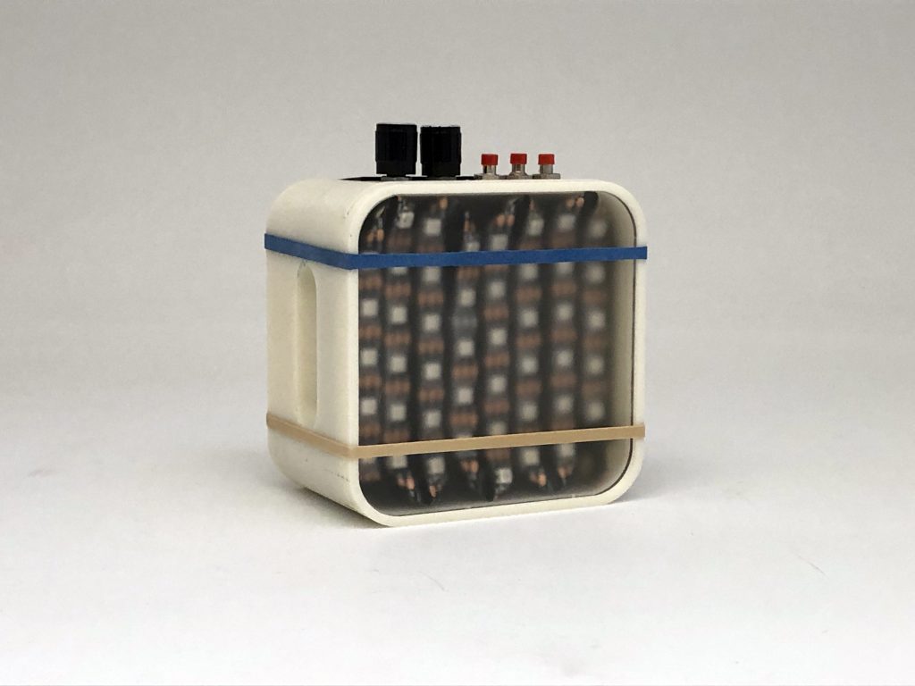
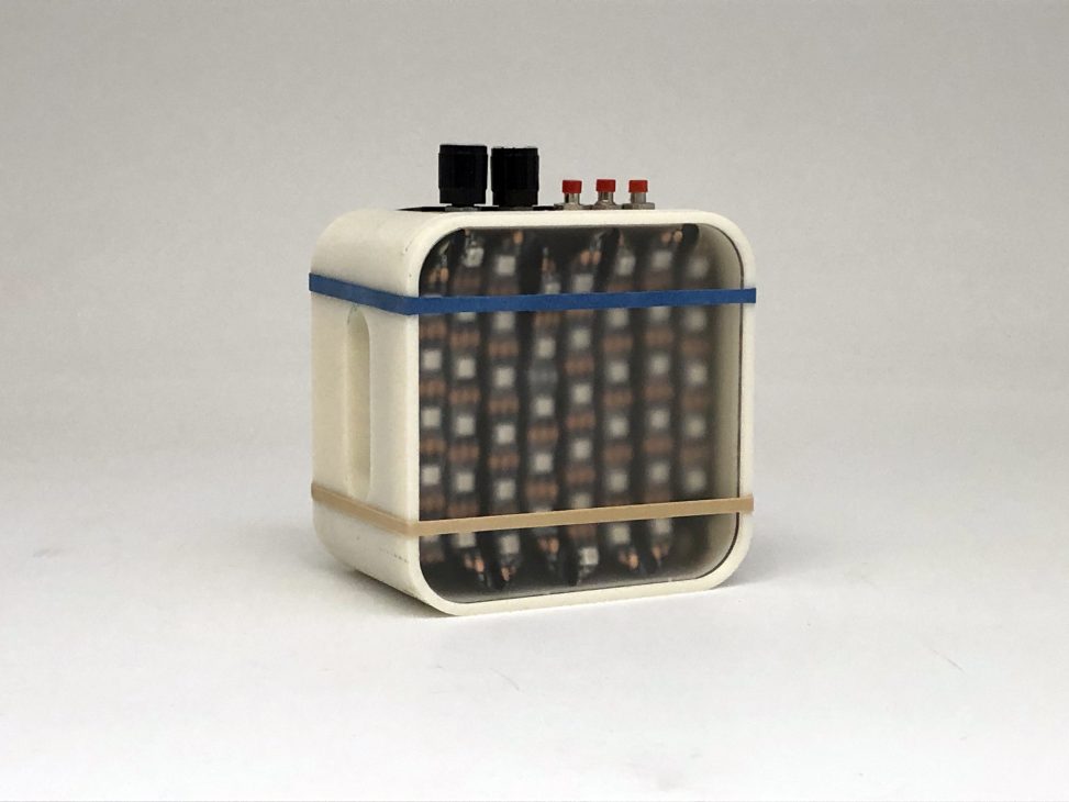
Overall photo of the device in its off state.
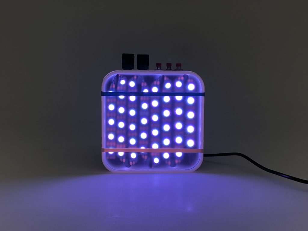
Frontal view of the device at cool color temperature and low intensity.
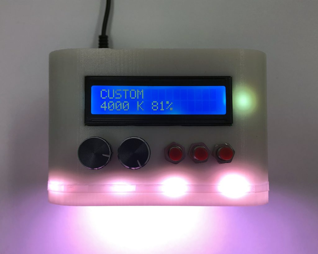
Detail view of the top surface of the prototype, including the LCD display, knobs, and buttons.
Demonstrating the features of the prototype.
The device is intended to be a light source that is capable of simulating natural light based on different parameters of weather and time of day. It has two knobs that correspond to color temperature and intensity, as well three buttons that correspond to a sunny, cloudy, and sunrise/sunset preset condition. It was designed as a portable device that Jeff could bring to the homes of his clients and hold up behind different samples of blinds in order to demonstrate their unique qualities (e.g. blackout, semi-opaque, sheer).
Process:
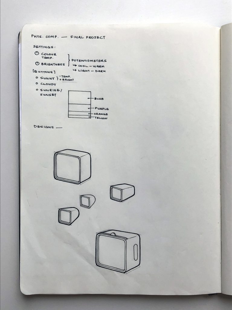
This sketch shows the notes on the initial parameters we intended on incorporating in the prototype. The design of the prototype was also fleshed out through drawing.
We focused on getting the color temperature and intensity features working as a first step. This was done with the Arduino Uno, an LED strip, and two potentiometers.
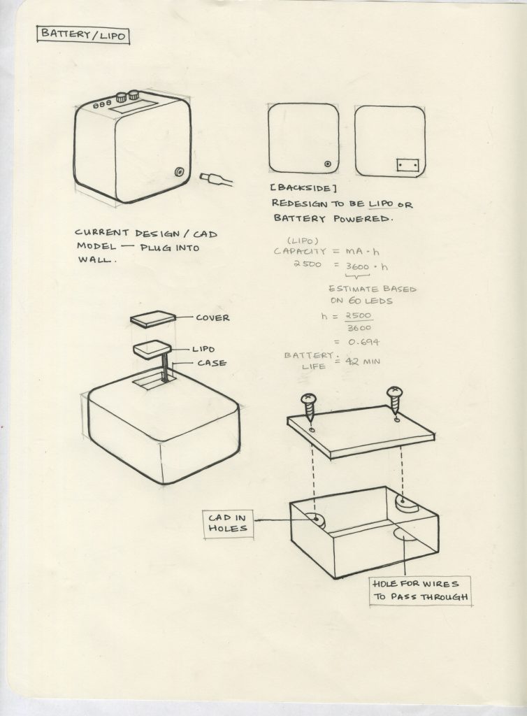
Early on, we were considering a battery powered design for the device to be more portable. However, we decided to make a plug-in prototype in order to concentrate our efforts elsewhere.
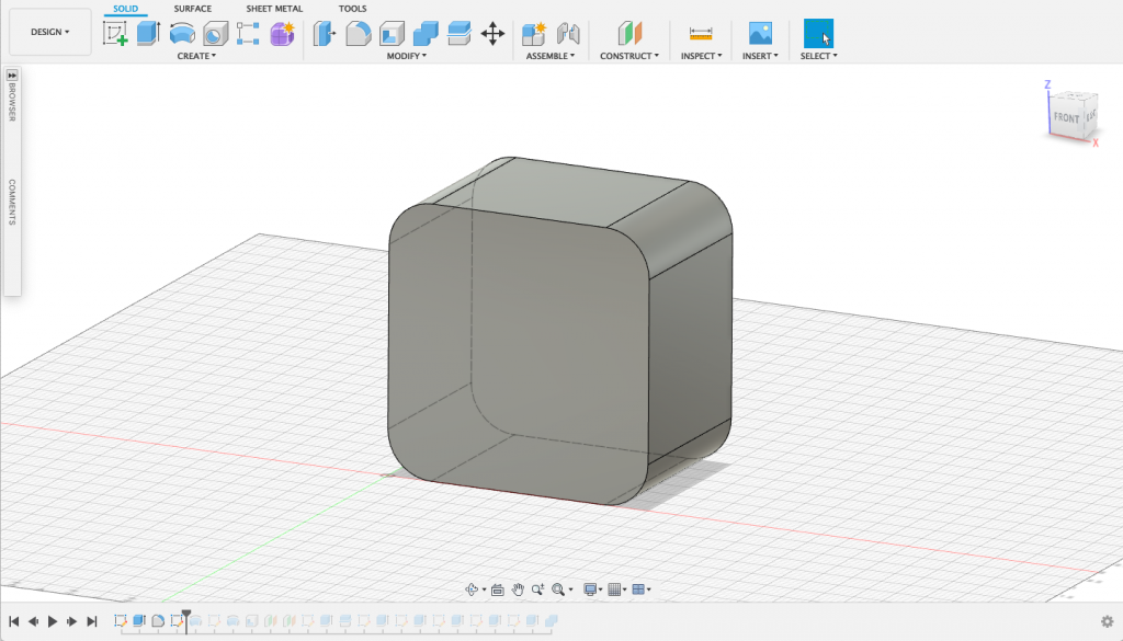
In terms of design and fabrication, the CAD work was done in Fusion 360 and 3D printed. A progression of the design can be seen as follows.
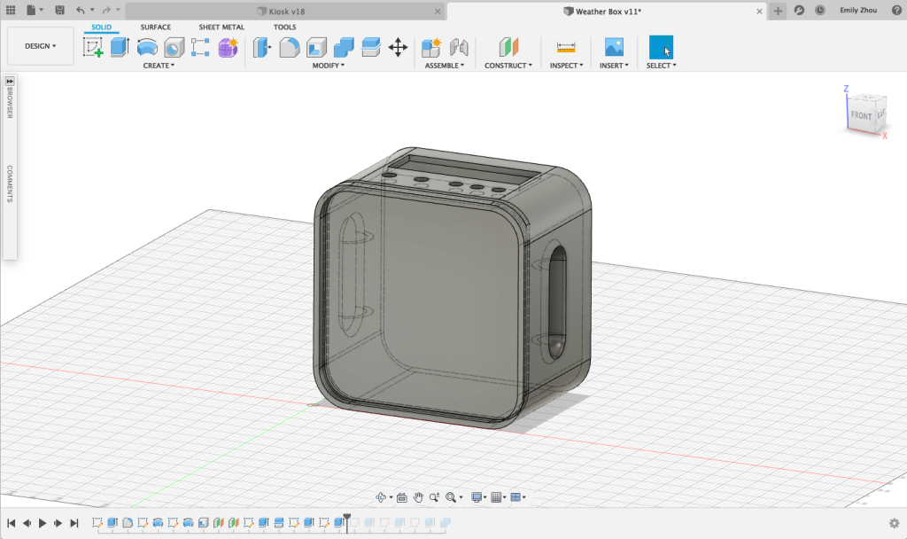
We included holes to wall mount the encoders, buttons, and LCD screen. We also chose to add an indent on either side to provide an easier grip.
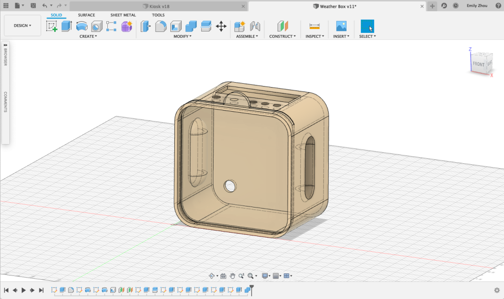
At this point, we began adding material appearances in order to visualize what the 3D printed outcome would look like.
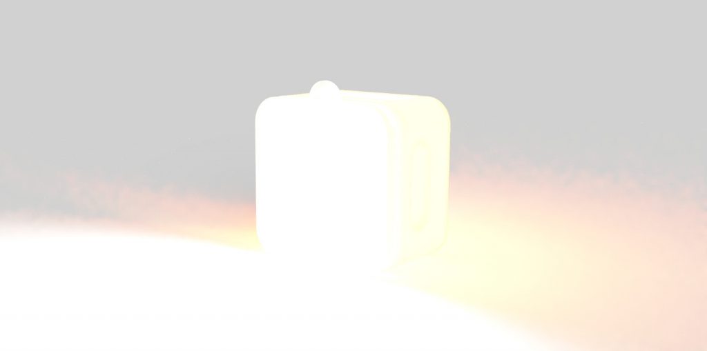
We also tried to render the form with a emissive appearance that was intended to represent the panel of LEDs. However, it did not come out very well.
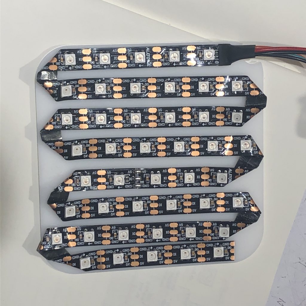
In unifying the electronic and fabricated components, we began by laser cutting a sheet of acrylic that fit inside the box, and bending the LED strip so that it covered the sheet. The LED strip had an adhesive backing so it was easy to apply. Later on, we had to remove the strip and remount it to a smaller sheet of acrylic, since this one did not fit.
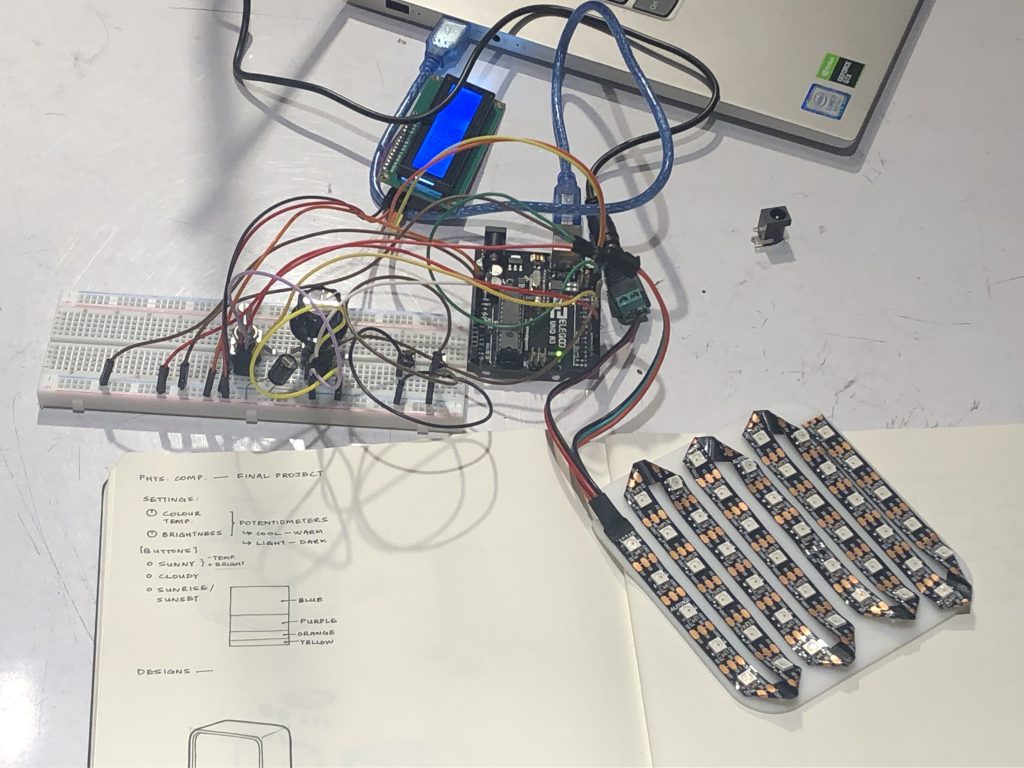
This is a photo of all the components we had working at this point. After programming the encoders (which were previously potentiometers), we added the LCD display.
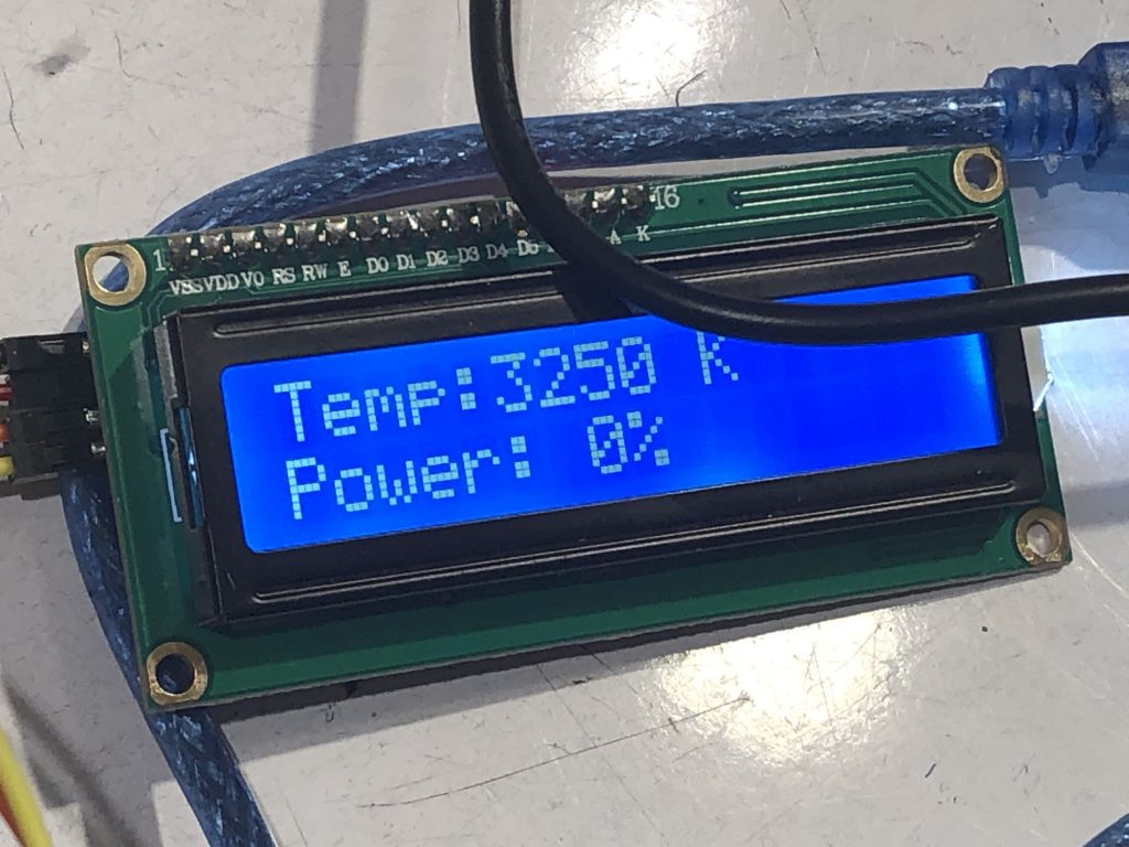
A close-up of the LCD display showing color temperature and intensity values.
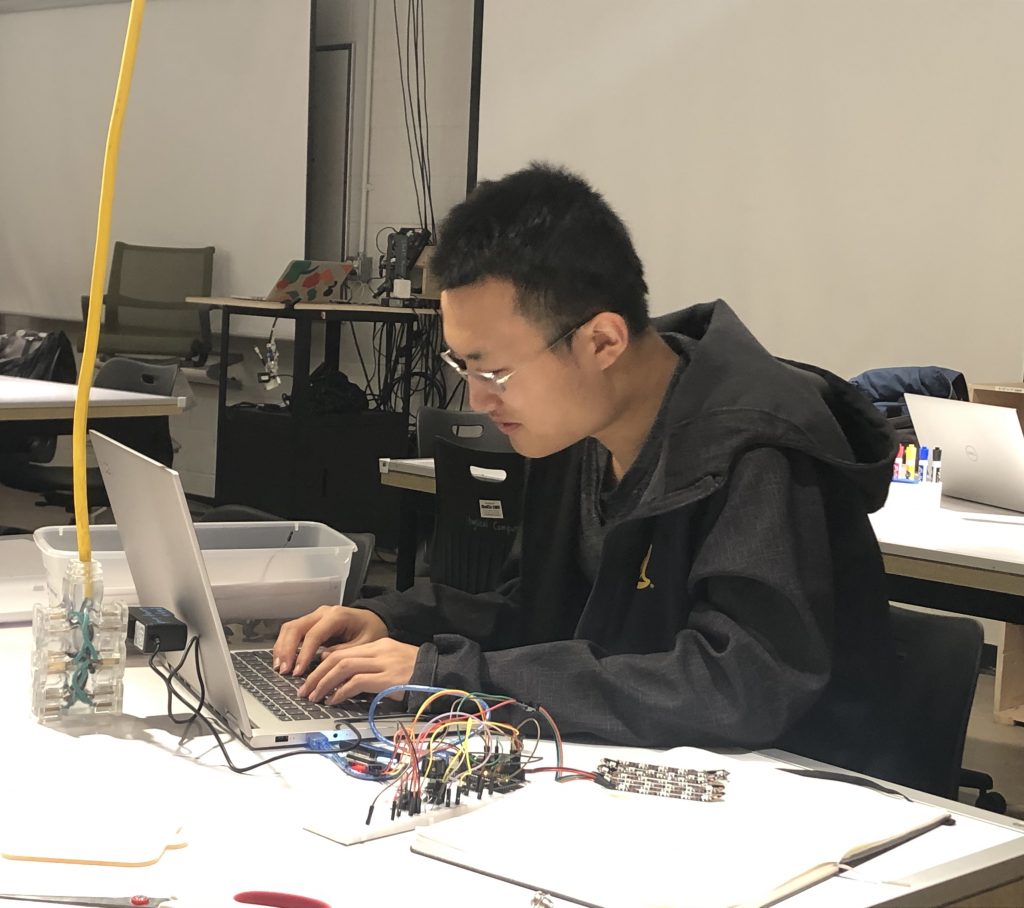
A photo of Larry writing the code for the button presets.
A gif that shows a piece of support going flying after being chiseled off.
Discussion:
Various challenges faced the development of this prototype, from the initial design to its exterior appearance. We had struggled for days to find a suitable design that could be of use to Jeff, but we eventually came up with the idea of this light that could potentially aid in his professional business and be within the scope of our project. From there, the basic design for a prototype came fairly naturally, such as the features of tunable controls and a few convenient presets. But we faced a certain problem when trying to transition between controls and presets. The potentiometers we initially used had limitations on the extent they could rotate, making it hard for a seamless transition from a preset setting to whatever we tuned it to, as we had to jump to whatever the potentiometer position was when we tuned the color away from a preset value to ensure that the knobs wouldn’t be at a, let’s say ‘high’ value while displaying a lower value, as turning the knob higher wouldn’t allow it to go much further, despite having more range available that the LEDs could display. Encoders resolved this issue since they had no limitations on how far they rotated. We also encountered some issues with removing the support material on the casing, since the device needed to do so was out of commission. Thus, we chipped away at it by hand. The end result might’ve suffered slightly in appearance, but fortunately, it performed as desired.
After our formative critique with Jeff, we were able to gain many valuable insights into the future steps for our project. Jeff informed us that, although he had used simulate lighting demonstrations in the past, they were large setups that are hardly portable within the trunk of a car. Thus, a portable light source that could do something similar, albeit on a smaller scale, could give him an edge over competitors who wouldn’t be able to show them such a presentation. This can be especially practical in an often cloudy city like Pittsburgh or when no daylight is available, where it can be hard to show customers how some blinds might appear on sunny days, or how well they can block out intrusive artificial light from the neighbor’s yard or light from the interior to protect the customer’s privacy. Part of Jeff’s job is showing the customer what are the best blinds for their needs, and this could certainly help with that. Thus, our concept had been met with approval, and we were also able to receive significant critique on our design regarding how we could improve it to fit Jeff’s needs, making for a very productive critique session.
Critique Inputs and Moving Forward
Among the the many pieces of advice we had received, several important points stood out. Since we had been aware of this drawback in the prototype, we weren’t surprised when the subject of the lighting brightness and color was brought up. Our prototype was using an RGB LED strip, but it wasn’t close to intense enough to achieve bright enough lighting that could actually simulate how sunlight would appear, which we intended to save for the final version when we knew we had a good prototype concept. Jeff also requested that we change the dimensions from a fairly square width and height to a rectangular one. Furthermore, he was interested in a slightly elevated design so he wouldn’t have to hold it up, freeing his hands to demo his blinds. We proposed building a stand and using it as a storage device as well, which worked for Jeff. Our prototype also didn’t diffuse the light enough, but we’ve got several solutions in mind, such as moving the light source further back from the frosted acrylic pane, since we had it fairly close in the prototype. Jeff had mentioned adding a heat feature of some sort, which we think the high intensity LEDs may make possible as an added bonus, although the intensity of this heat is uncertain.
Aside from those major goals, there were several other minor changes we also discussed. While we had initially brought up storing more presets with Jeff, which was a good idea, we eventually learned that he probably wasn’t going to need more than 3 presets like we had on the prototype, so any others could be tuned himself. Jeff had mentioned using a rocker switch as he didn’t need the fine control, but we concluded we would probably stick with the current input design as it worked anyways and didn’t suffer from bouncing. On the aesthetic side, Jeff requested that it come in black, which would be doable. While he had been fine with the tactile interface as it met all practical needs, it was not without possible improvements. We considered that slightly larger knobs might be nice, but since we had already ordered buttons previously that were similar to our current ones, we were probably still going to use them.
Overall, our priorities were going to be programming and wiring up a new light source, setting up new presets and adjusting the acrylic window to approximate real world lighting conditions, adjusting the dimensions, and building a stand. Following those will largely be aesthetic goals that we hopefully can accomplish after taking care of our priorities.
Timeline:
Fri. Nov. 15 – Research and submit request for brighter LED module
Sun. Nov. 17 – Finalize CAD for new design, submit to Stratasys
Tue. Nov. 19 – (in class) If printing is complete, remove support material. Otherwise, design and laser cut acrylic pieces (LED backing, diffusing cover, stand elements). Programming and hardware.
Thu. Nov. 21 – (in class) Design and laser cut acrylic pieces. Programming and hardware.
Sun. Nov. 24 – All electrical components finalized and working, stand fabrication complete.
Tue. Nov. 26 – (in class) Finish 3D print (sand and spray paint)
Thu. Nov. 28 – (in class) Finish 3D print (sand and spray paint)
Fri. Nov. 29 – Finishing and spray paint complete
Sat. Nov. 30 – Final assembly
Tue. Dec. 3 – Final project crit.
Comments are closed.