Introduction
Team Jim consisted of Nicholas, Jeena, Leland, and Jim. We were tasked with helping Jim in his daily life with an electronic device that we could build for him. At first it was hard to find a real problem that we could help fix, but with a little more exploration of his daily life and house, we found that Jim has a piano in his living room that needs to be at certain humidity in order to be maintained. We combined this with the fact that Jim has a lot of fountains in his house, so we made a fountain that could read the humidity in the living room and humidify the room if needed.
You can see our initial meeting post here and our prototype post here
What we built
We built a fountain that will humidify Jim’s living room based on the humidity level that he wants maintained. The humidity is measured by a remote part that can be placed wherever in the room, and the fountain can then take the data from the remote part and activate the humidifier when needed. The fountain itself has a knob for which Jim can turn to set the humidity level that he wants the room to be at. The purpose of this fountain is to automatically maintain the humidity in the room if he wants to while also serving an indoor fountain that supplies the calming sound of flowing water.
Narrative Sketch:
Its the time of the year again where Jim knows he needs to bring in an external humidifier to maintain the humidity for his piano. However, he remembers that a couple of CMU students built him a fountain to monitor the humidity and humidify the room. Jim then plugs in the fountain if it isn’t already, then he sits back in a chair in his living room watching the fountain spewing a satisfying mist of vaporized water.

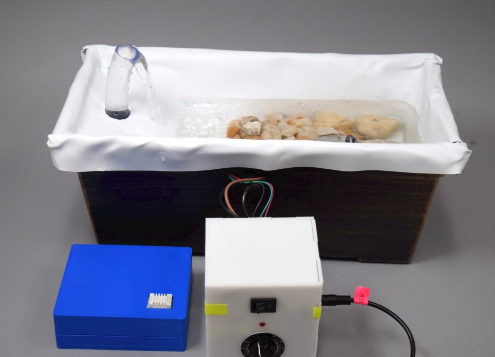
A photo of a working running second version of the final project. The LEDs are not on because the remote part was not turned on during the photo shoot session, but everything’s working, including the pump, LED strip, humidifier, low-voltage LED indicator and the humidifier and set point potentiometer.
First iteration
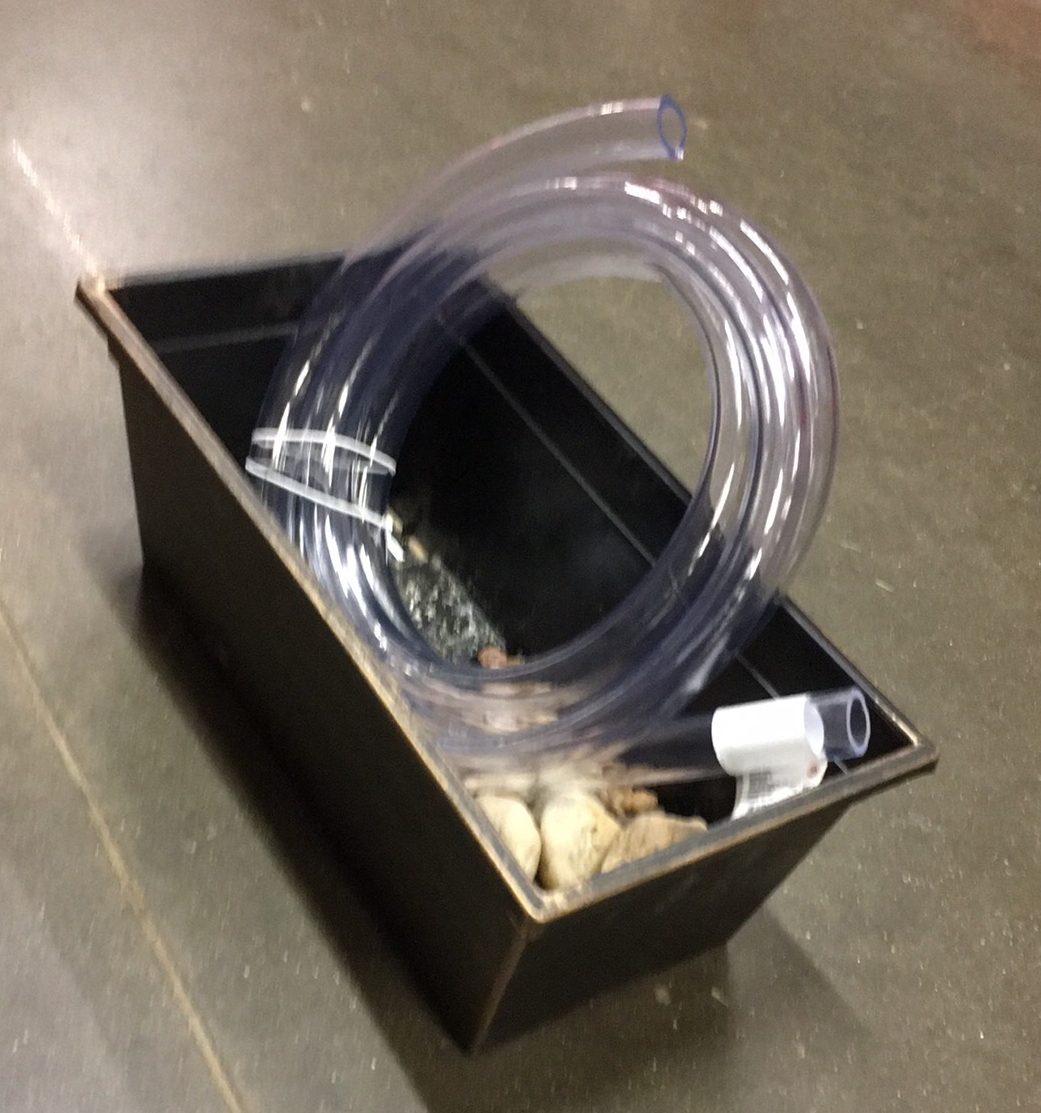
The main fountain part of the first iteration.
The first iteration of the main fountain part has a round base that traps the mist underneath it. In the gif, you can see the mist only as you lift up the top part.
Second iteration
A second iteration of our final project. Here you can see a new ‘stage case’ design of the top part where the water can create an ambient water sound while flowing down. The humidifier is exposed in the air such that it can directly humidify the room (as opposed to being underneath the top part in our first iteration and not able to humidify the environment).
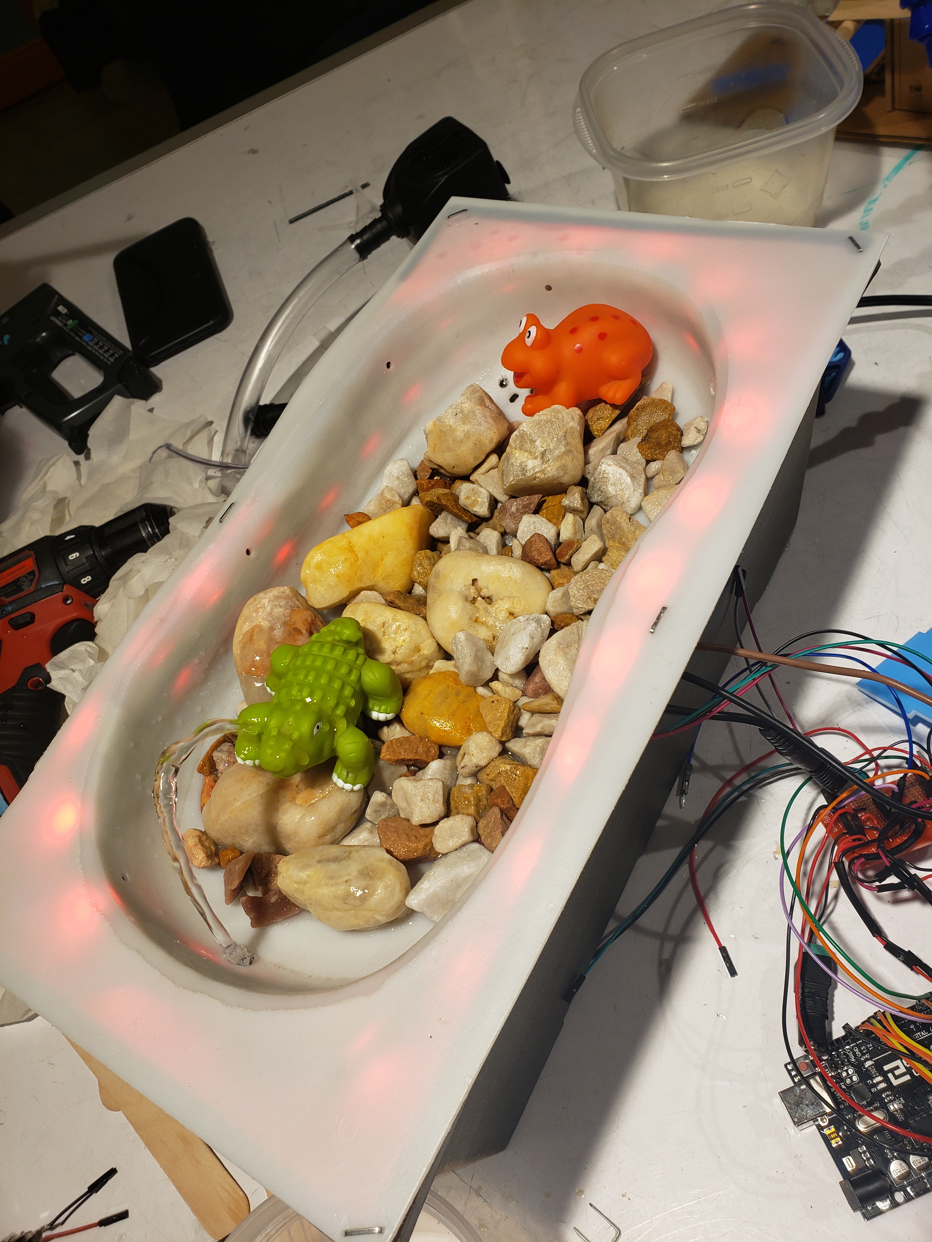
Turning the set point potentiometer allows the user to adjust the threshold that determines when the humidifier gets turned on. When the humidity is slightly above the threshold (within 10%), the LED strip shows a rainbow color. When the humidity is above the threshold + 10%, the LED strip becomes blue. The LED strip shows full red color when the humidity is below the threshold and the humidifier gets turned on.
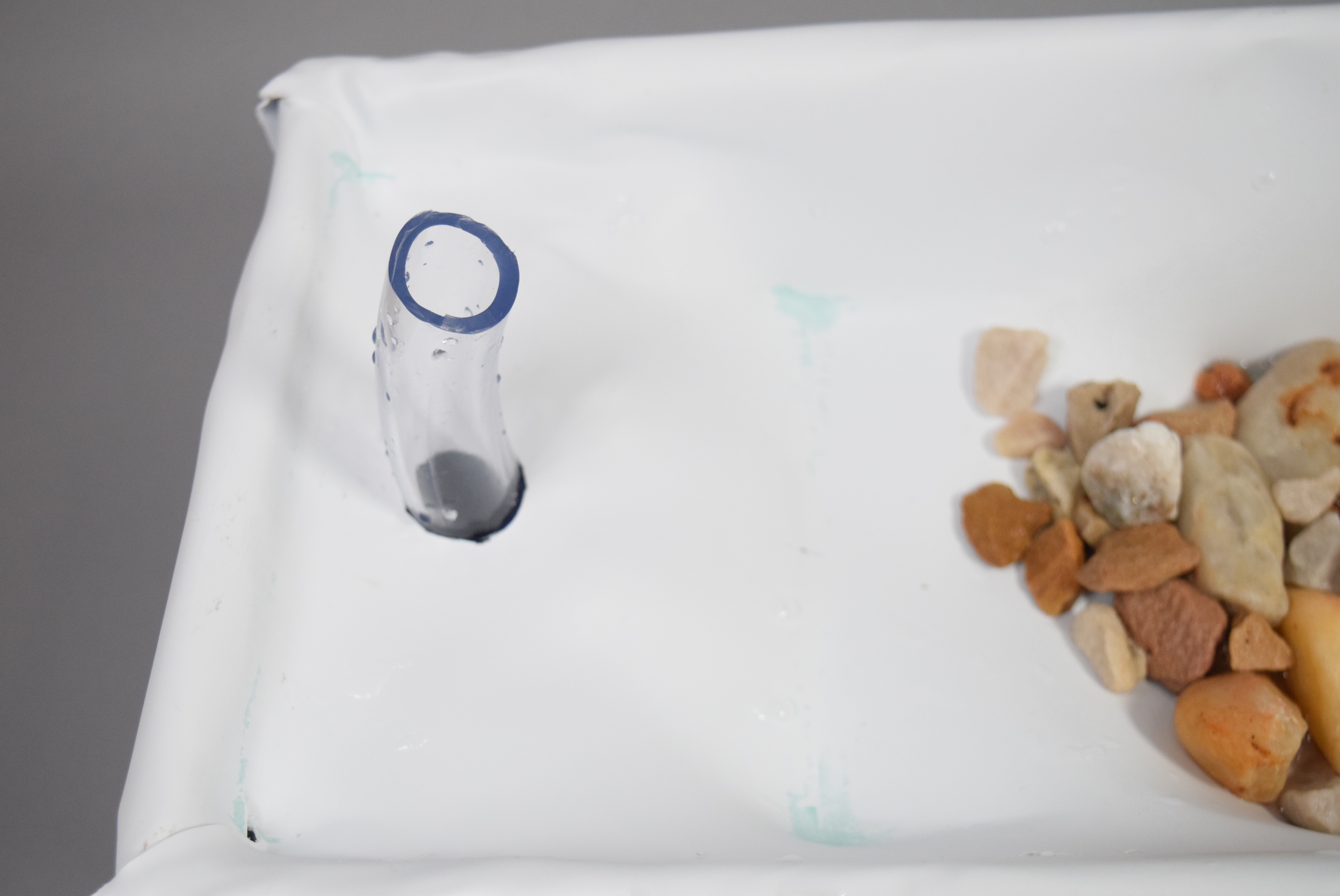
Detail of the nozzle of the second iteration of the final project. This is where the water comes out directly from the pump. This nozzle creates a height such that the water creates an ambient water sound.
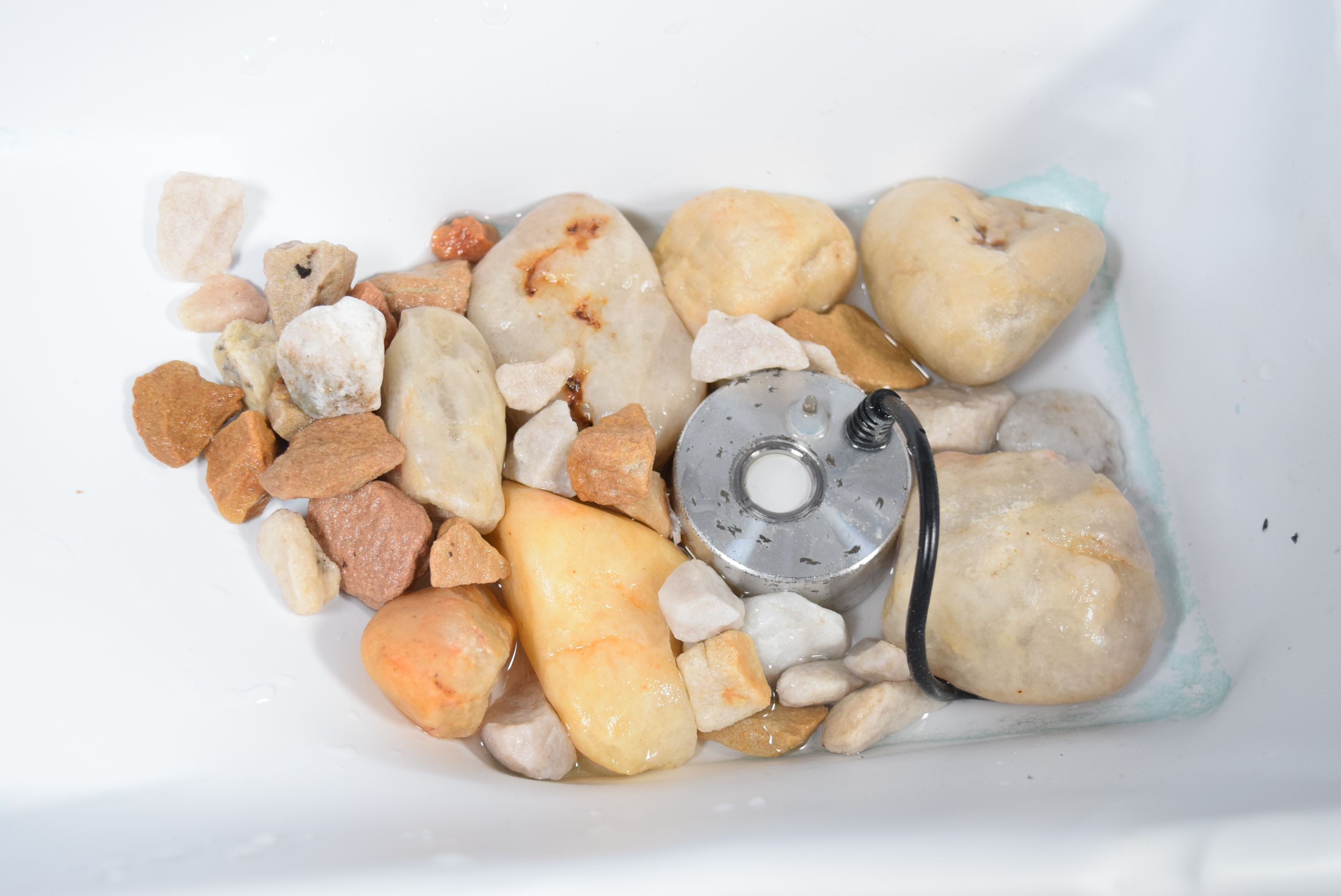
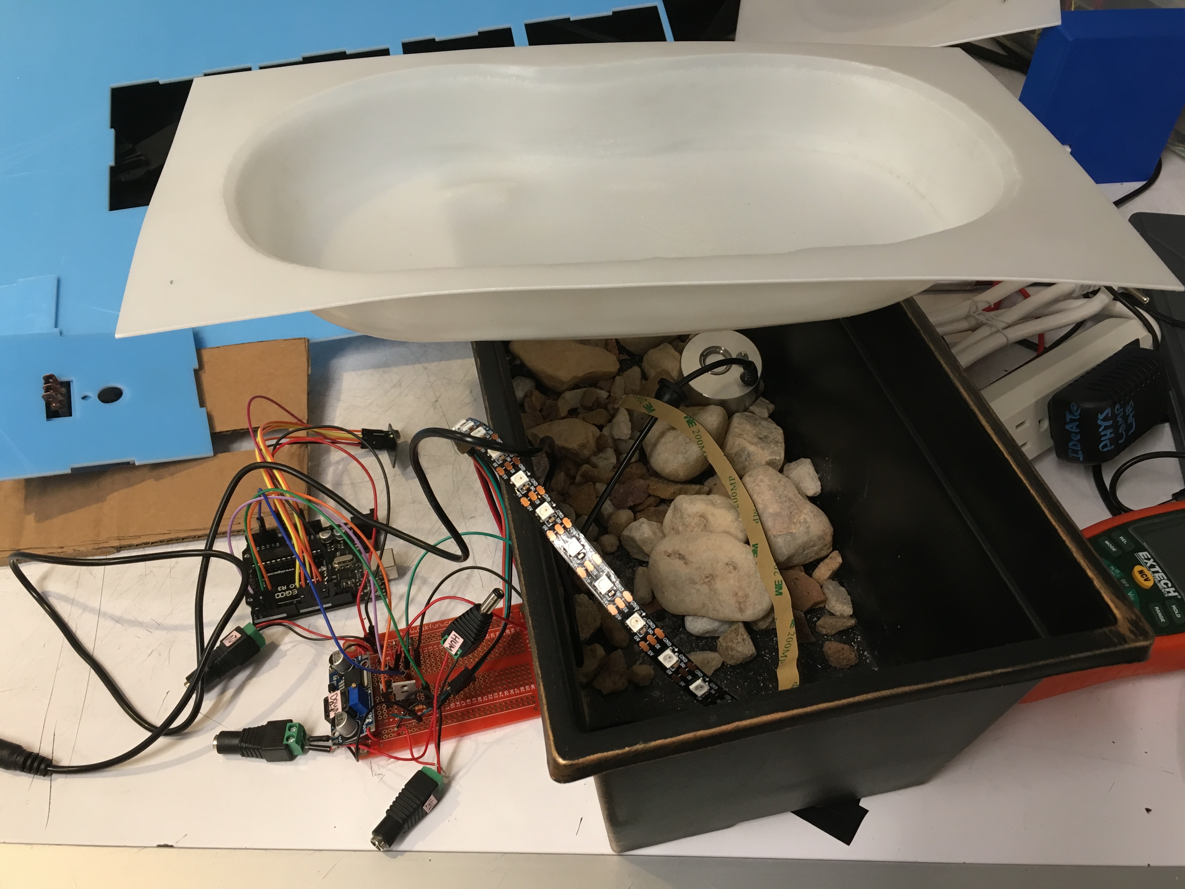
A top-down view of the fountain main part. The humidifier lays among the rocks.
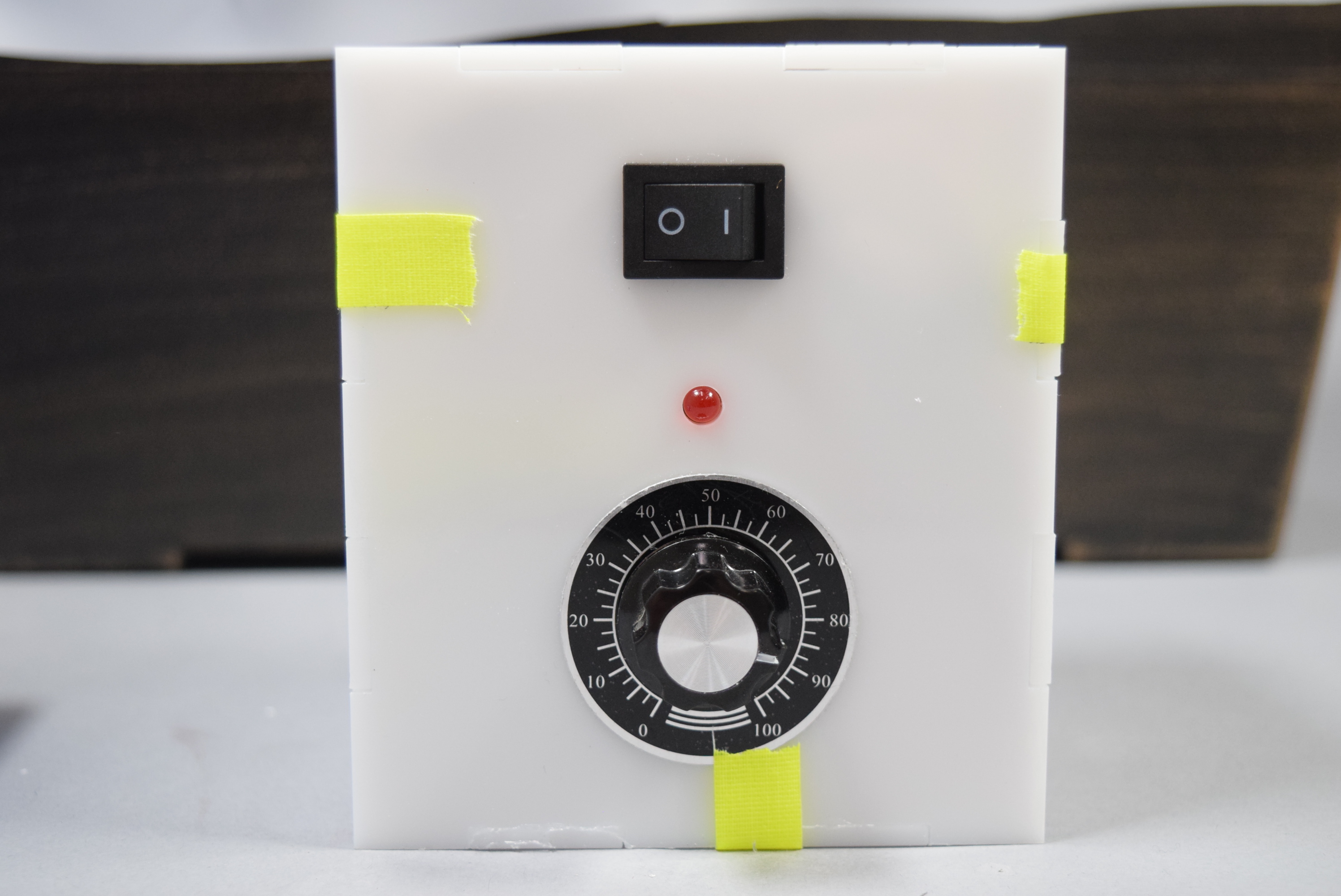
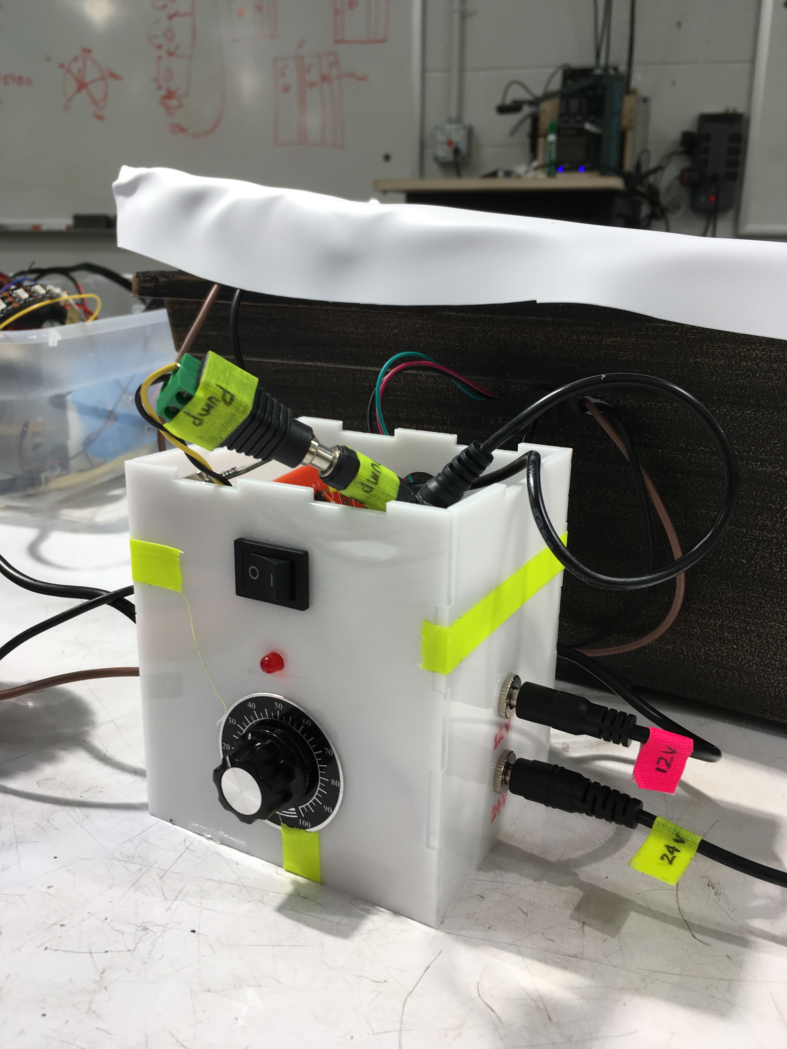
The main control panel for the second iteration of the main fountain circuit box. The potentiometer has a nice numerical label that shows the set point for the humidity. The switch has on/off indication.
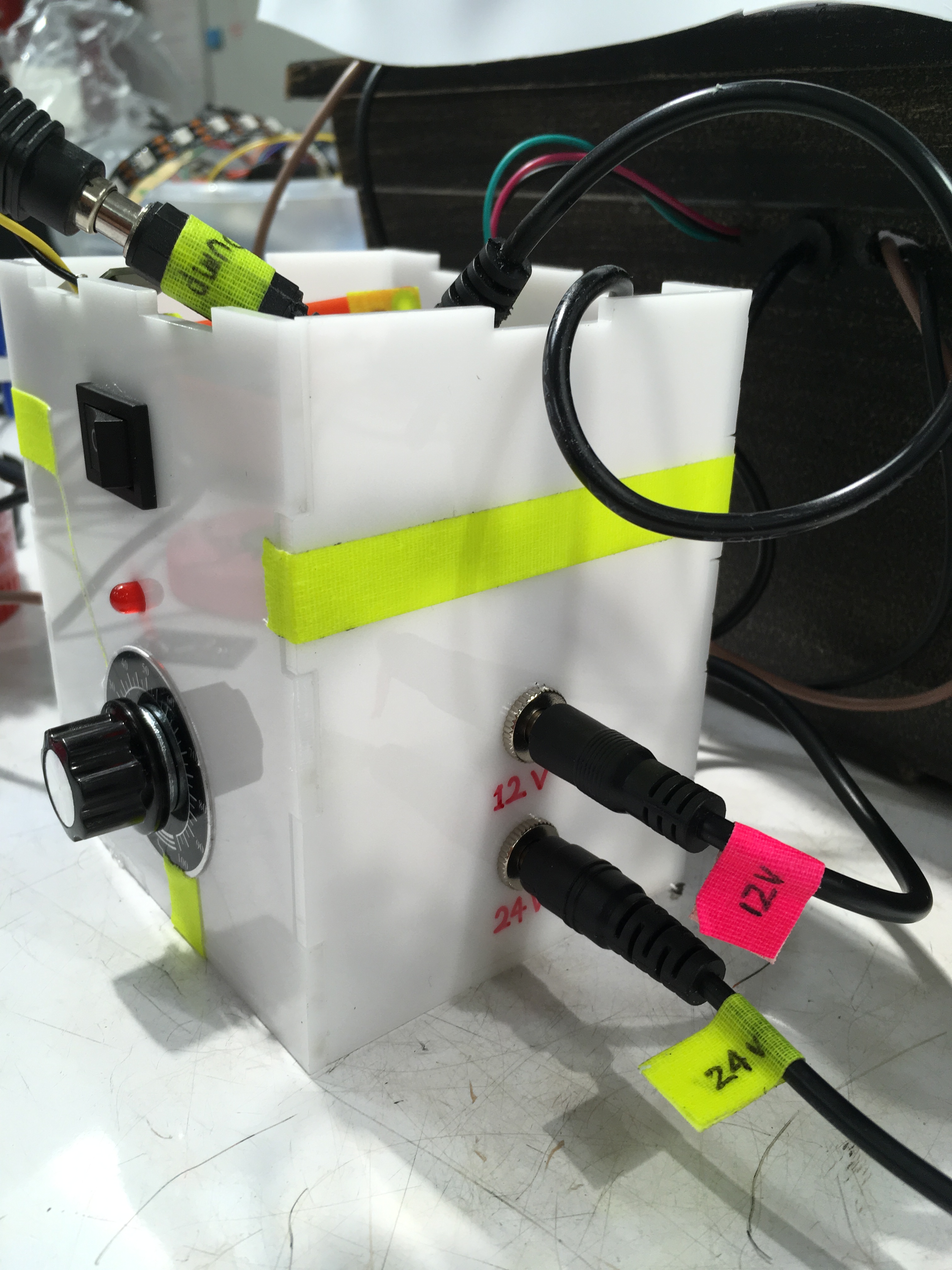
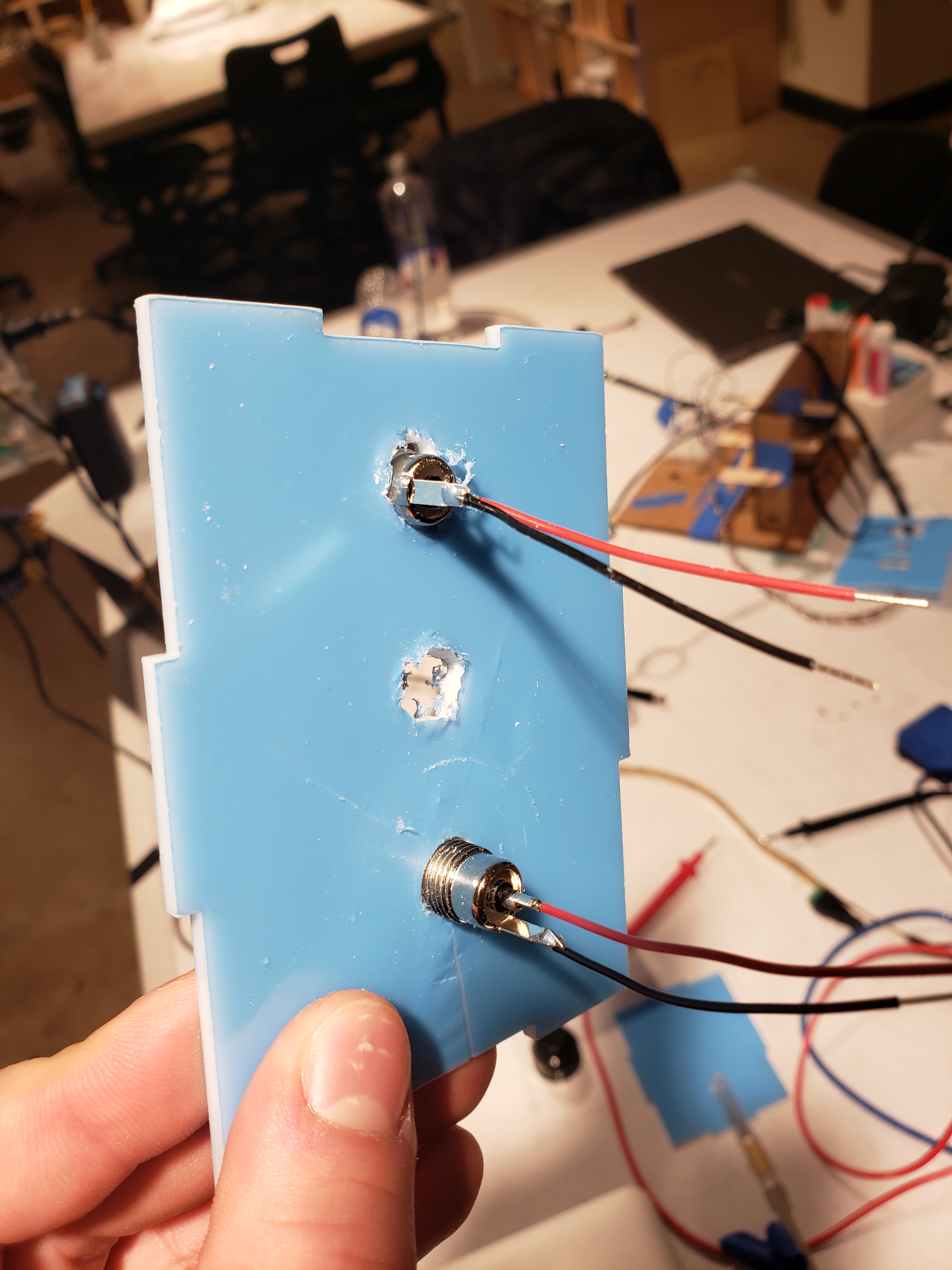
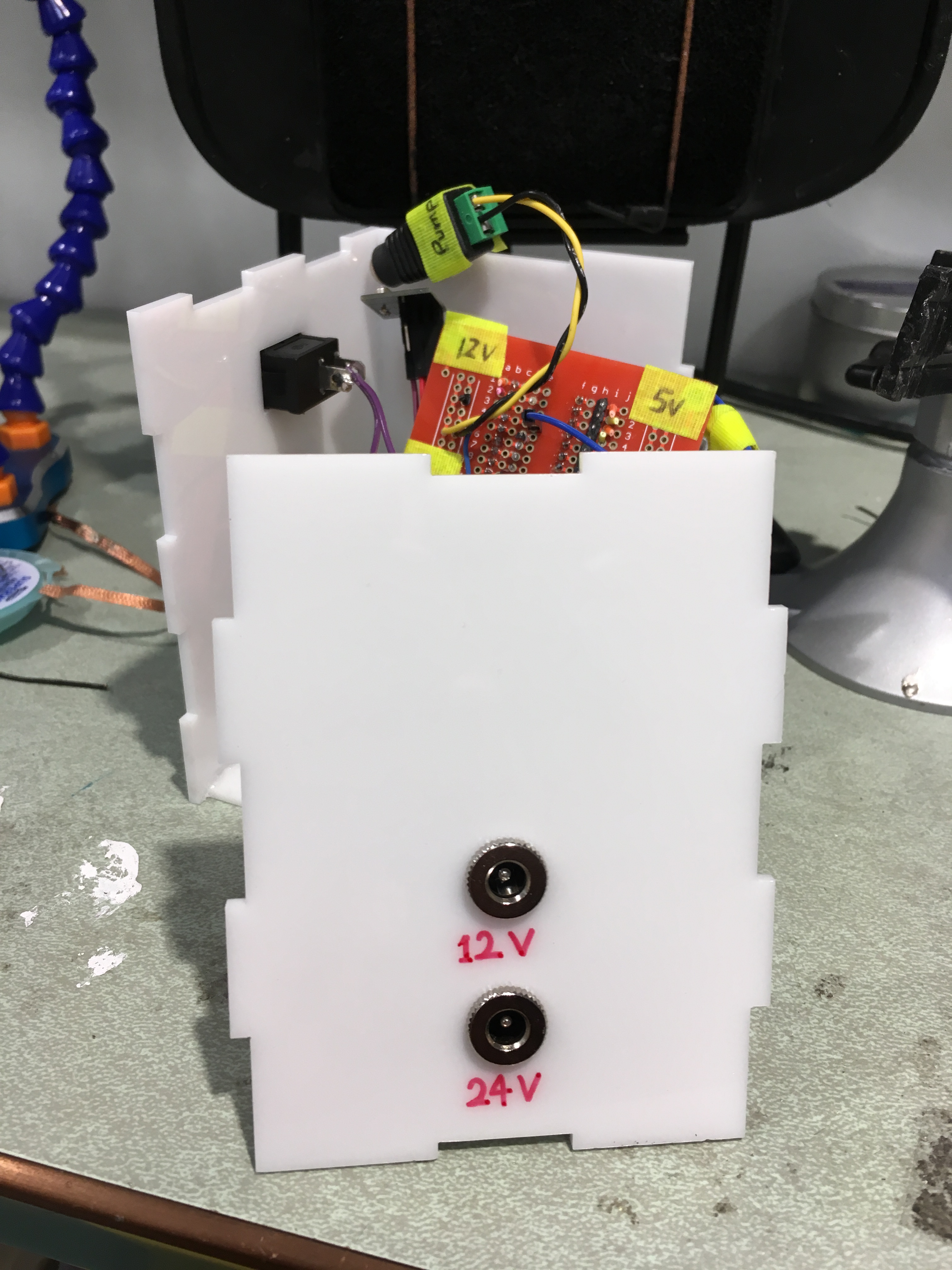
The second iteration of the main circuit box needs ‘only’ 2 power supplies. The power supply holes are labeled with permanent marker.
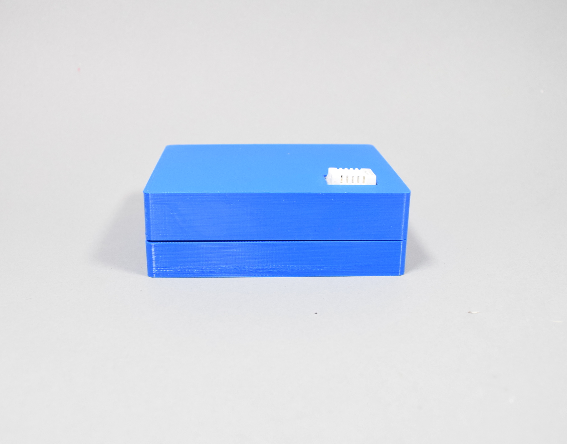
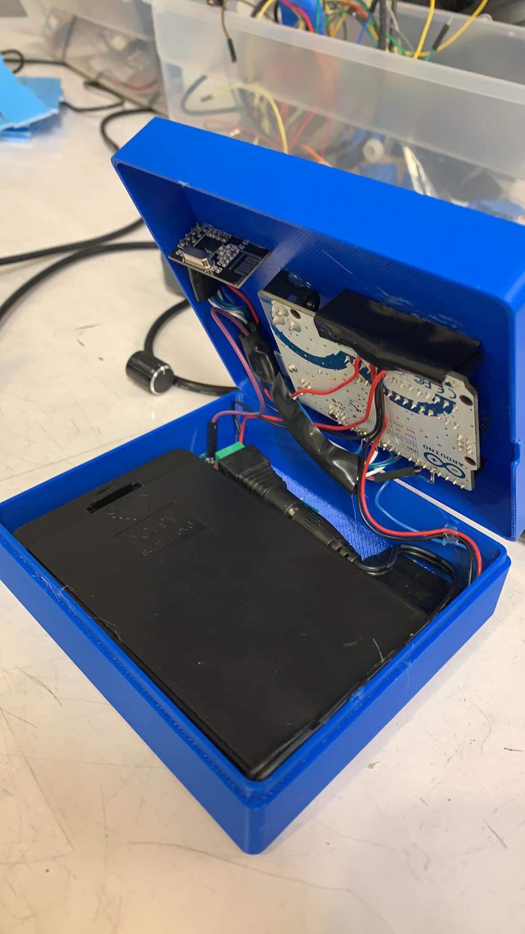
The look of the second remote box. It has an embedded radio sender (inside the box) and a humidity detector (where the white part is).
How we got here
One thing our group seemed to be very good at was making things difficult for ourselves. From the beginning, the journey from conception to delivery of this fountain was plagued by a variety of setbacks. We had left our initial meeting with Jim, quite convinced that we would be solving one of the two largely mechanical problems he had lain out for us as clear difficulties in his life. Upon further inspection (and prompting from Zach), we reached the conclusion that perhaps we hadn’t though broadly enough about the problem statement and possibilities for this project.
As our team has done time and again, we decided to revise our approach and try again, returning to gym with fewer expectations and only a vague goal of getting to know his and his wife’s lifestyles better rather than find a specific problem to solve right off of the bat. What we learned from this approach turned out be far more stimulating for the ideation process than our prior meeting. We left knowing that Jim and his wife both enjoy music (their Boston grand-piano being a centerpiece of their living room) as well as the ambient sounds of running water. And so we resolved to create a fountain that would provide a pleasant trickle as well as automatically regulate the humidity in the room to maintain the health of their piano.
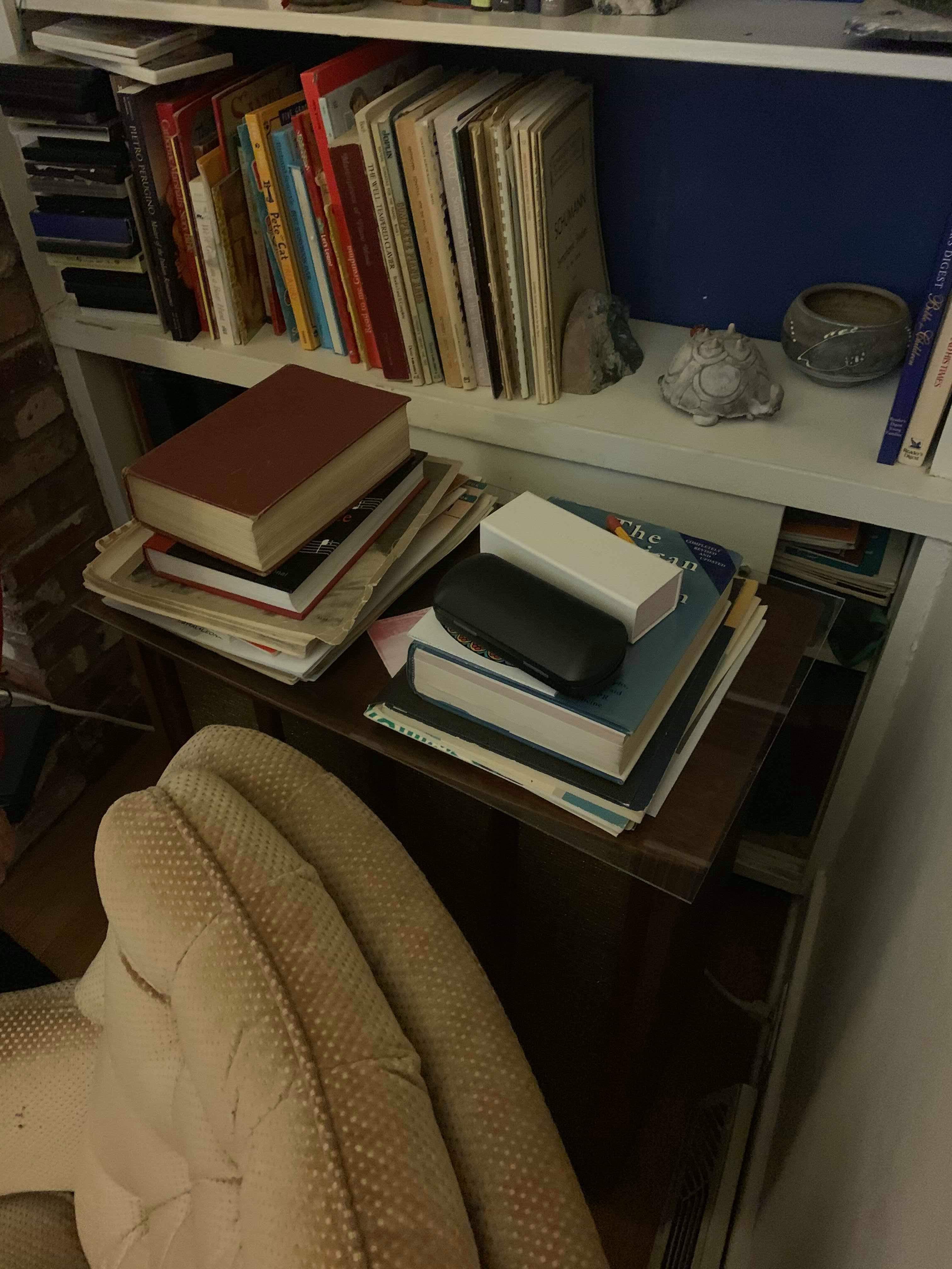
The shelf were we intended to place the fountain in Jim’s house..
First iteration
Getting the materials for the first version of the main fountain part from Home Depot.
The materials for the first version of the main fountain part.
The design of the first iteration top part.
The laser-cut side panel for power supplies for the first iteration final project. The holes were cut manually without drill bits.
The main fountain part circuit box of the first iteration. It has 4 power supplies.
From this point onward, we were sure we knew what our biggest challenges were. Though there would have to be some technical/electrical work behind our design, the most daunting task would surely be engineering and integrating the various physical/mechanical elements of our design. How would we print or manufacture the curvature of a custom bowl? How could we keep things waterproof? And what kind of pump fit our use case?
A successful prototype critique brought with it a renewed confidence that we were on schedule.
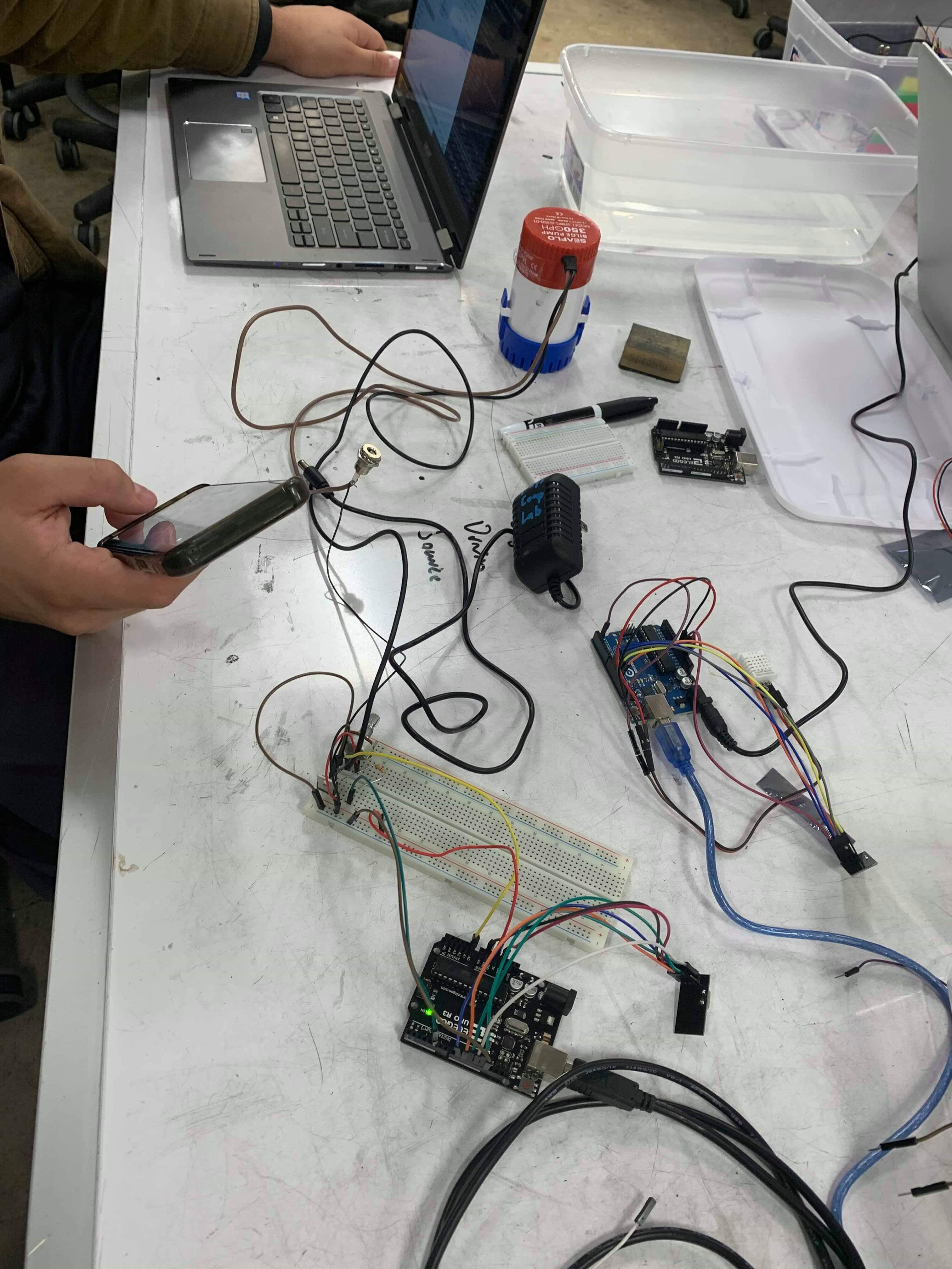
Despite a slightly shortened timeline, the prototype critique came and went about as successfully as we could have asked. Our core hardware seemed to work as intended (at least when lain out on a breadboard) we had planned a tight schedule that emphasized starting our manufacturing and building as soon as possible. With the awkward timing of thanksgiving some delays did start to pile out. We didn’t order new pump or humidifier as early as we had intended and the vacuum forming needed to create the base and top basin for our fountain couldn’t be completed until after the break or the Sunday before the project was due.
These delays were result of a variety of factors. Not least of which was the fact that in many ways were in a bit in over our heads and unprepared for the amount of work still left to do to produce a finished product. So, when the eve of the final critique came around, it was all hands on deck. We first had to redesign and adapt to the fact that our original base design could not work. The vacuum former simple hadn’t provided the necessary minimum of four inches of depth to allow it to work, so we improvised by purchasing a base and using our original base as our new basin.
By the time we finished our “final” product, it was nearly seven in the morning, but we felt confident that we had been successful in our effort—event if we had required attaching four separate power sources to our base due to voltage supply and current draw issues we had been unable to solve earlier in the week.
When we arrived for our final critique, we confidently plugged our fountain in. To our surprise, it seemed to be a definitive success with a better stream of water than we had seen the night before and at least some humidity streaming out from the bottom. Of course, this was promptly followed by a smoking power-supply, a quick pop, and all of our electronics dropping immediately dead.
Second iteration
Remote part final box
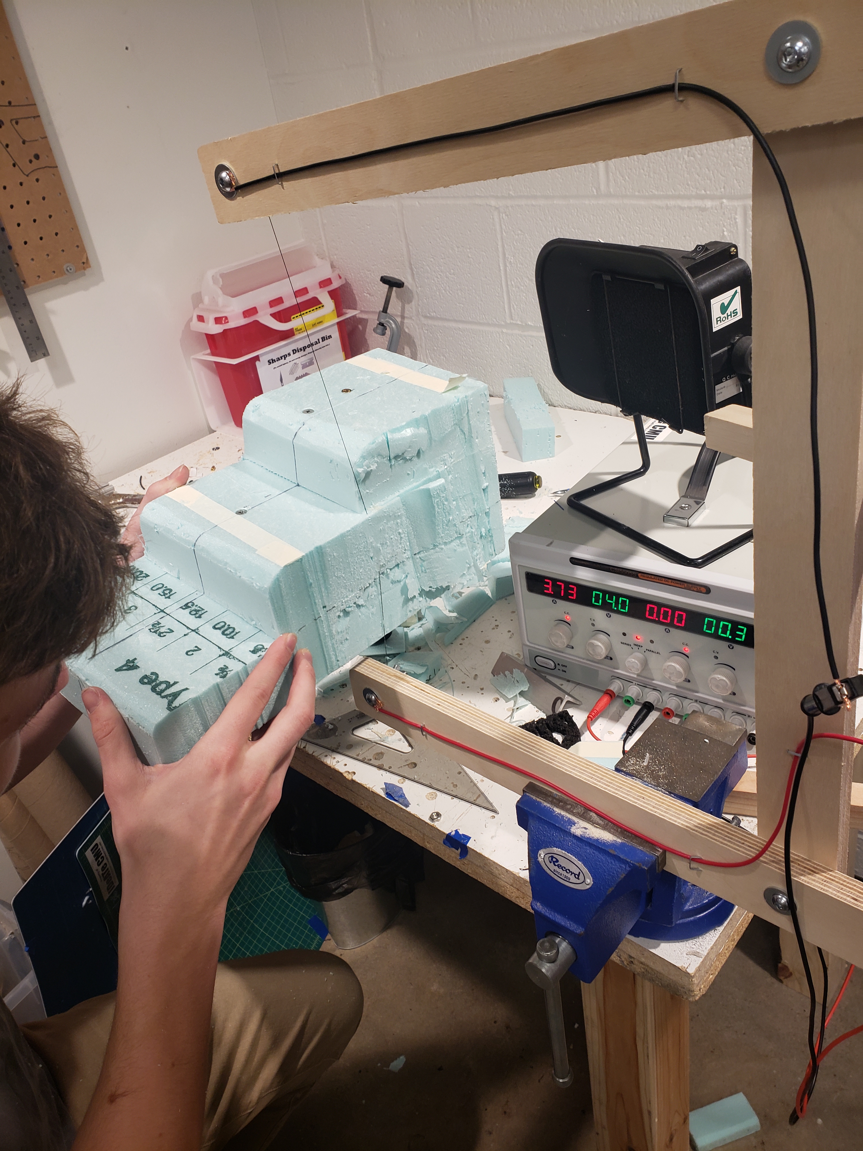
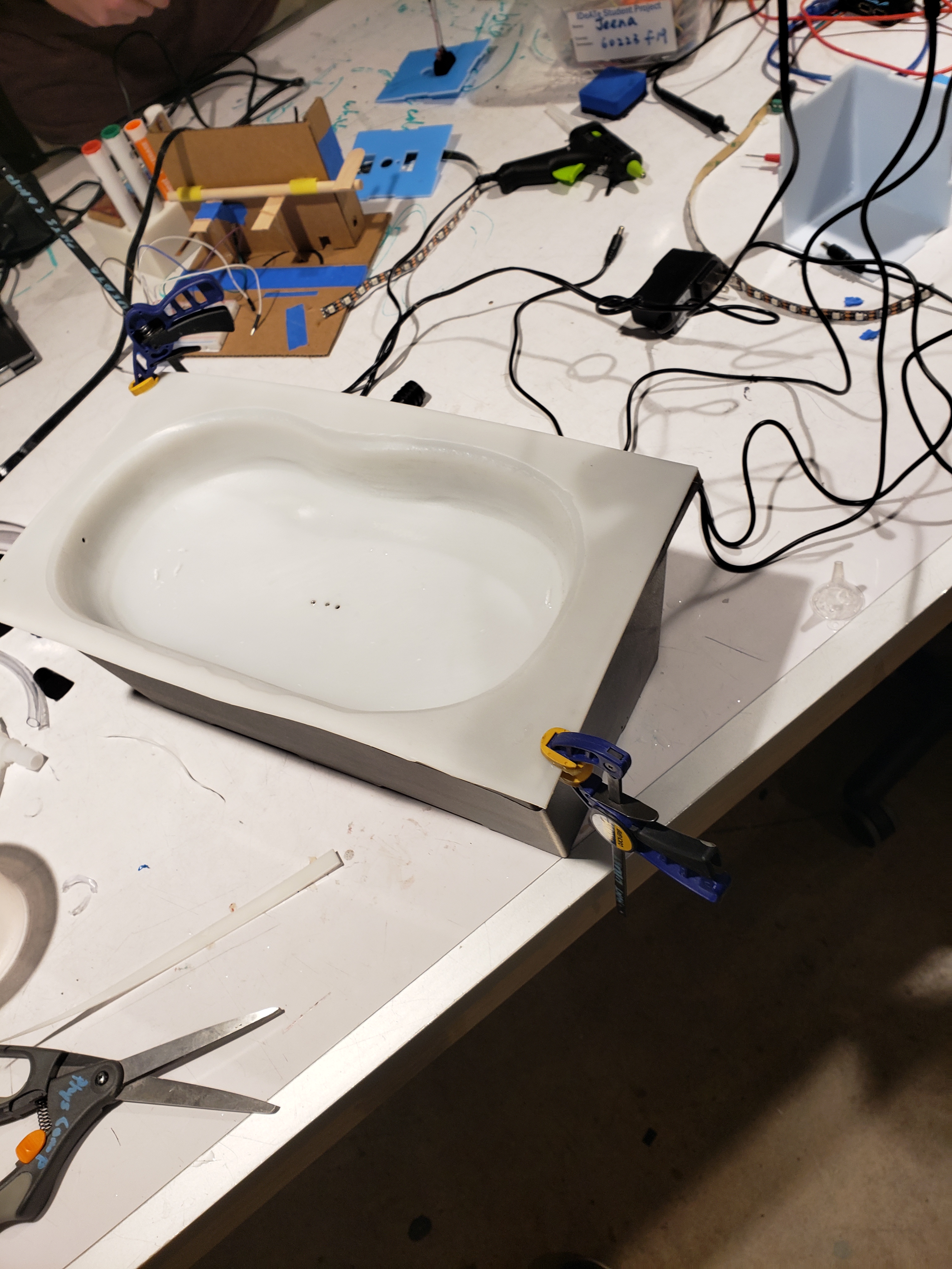
Nick was cutting the foam for vacuum forming the second iteration of the main fountain part.
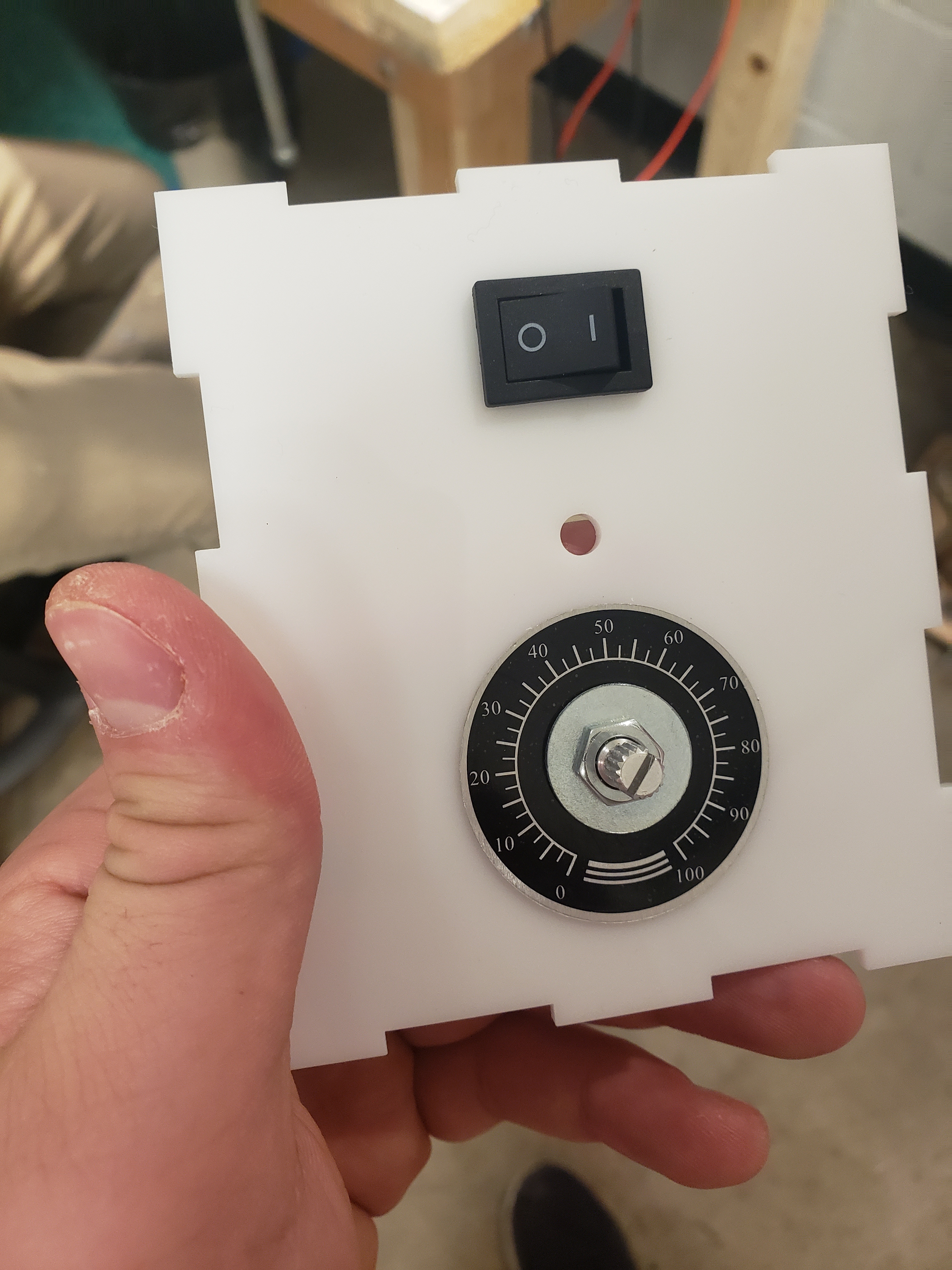
The main control panel for the second iteration of the main fountain circuit box. The potentiometer has a nice numerical label that shows the set point for the humidity. The switch has on/off indication. The middle hole is for the low-voltage LED indicator that lights up when the remote box’s batteries are low.
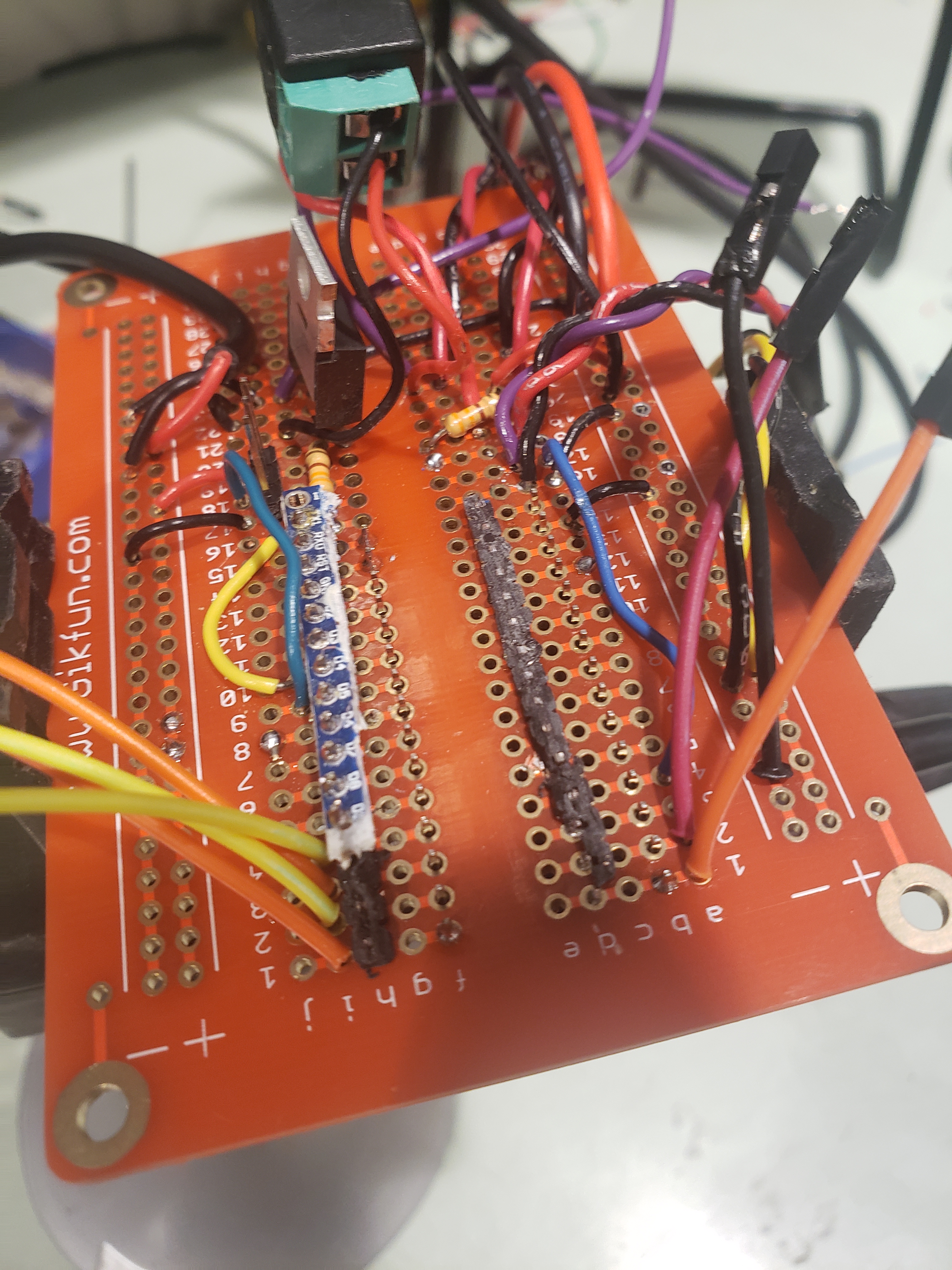
For the second version, we made a mistake of soldering an Arduino nano directly onto our main circuit board. The nano stopped working and then we had to brutally destroy the entire Arduino nano with a heat gun and remove it from the board. In the photo, you can see the cut off pins that were connected to the nano.
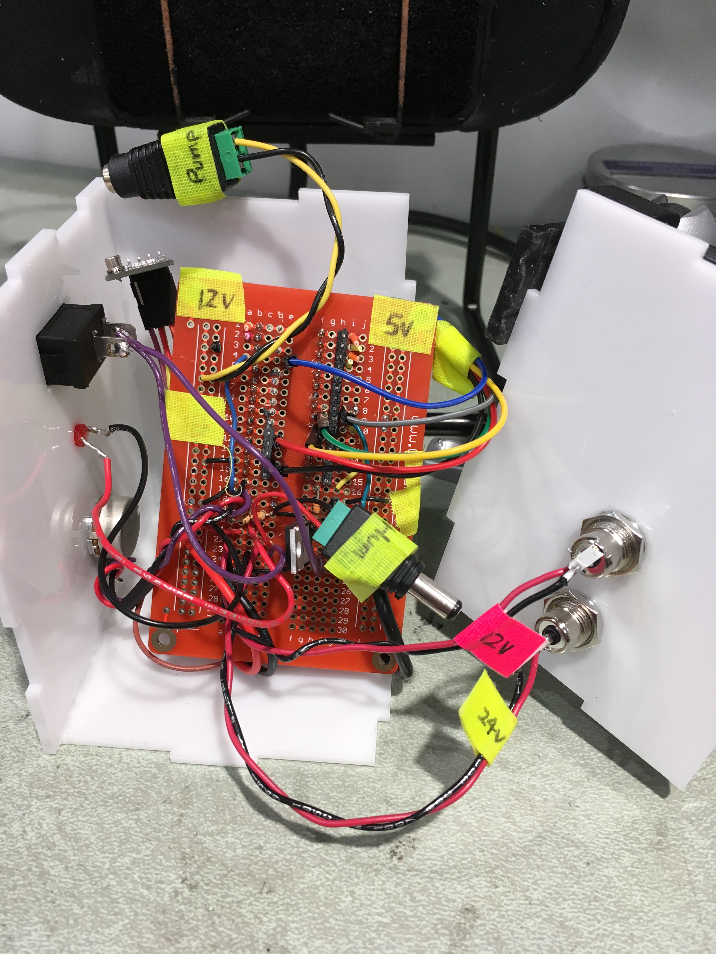
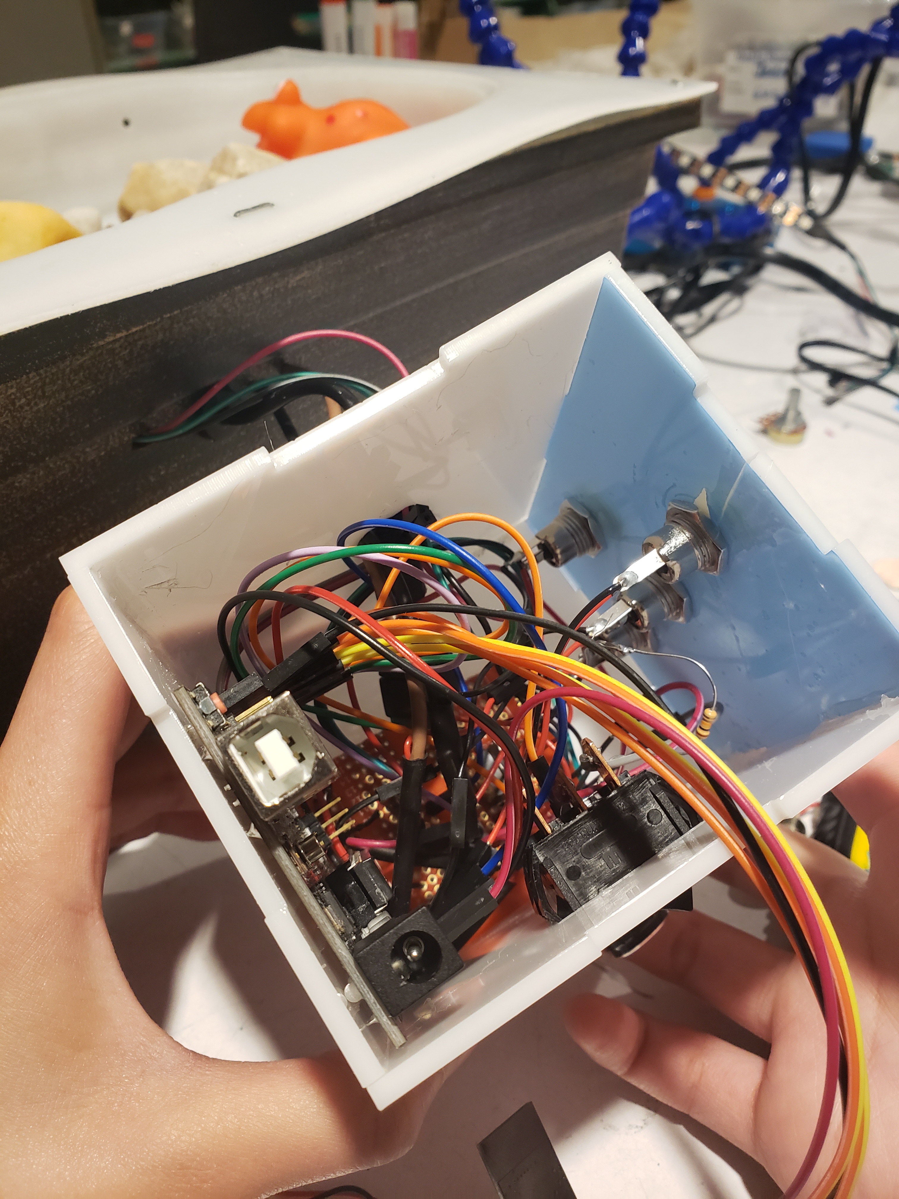
Assembling the circuit box for the second version of the final project that needs only two power supplies. All internal connections are labelled.
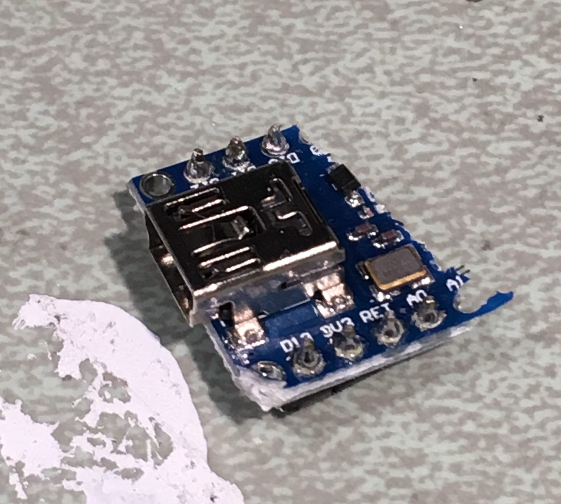
This is the head of a beheaded Arduino Nano. We soldered an arduino nano onto the second iteration of the main circuit box and ended up having to destroy it because it stopped working. Then, for the second iteration we switched to an Arduino Uno as we did for the first version of the final project.
The second iteration of the main circuit box needs ‘only’ 2 power supplies. The power supply holes are
In hindsight, this sort of outcome could have been at least expected if not anticipated. The continuous last-minute scrambles we seemed to create for ourselves surely bred minor mistakes or oversights that culminated at the worse possible moment.
In the end, with the combined efforts of our team, the understanding of Jim, and the grace of a certain instructor, we were given further time to rethink elements of our fountain and come together to produce a final product. Major steps included reforming our basin, replacing the pump, and re-soldering our circuit inside a new box with only two power outlets (thanks to a new 12v 5A power supply). With all of this, the new fountain is actually able to humidify a room properly, regulate its own water level passively, and actively change its LEDs in response to the measured humidity of the room.
Conclusions and lessons learned:
There was a lot to be learned from this project. As a group, we spent a lot of time learning from our mistakes and shortcomings and most importantly trying again and again when certain things didn’t go our way. At these times, what was often most helpful was taking a second to reconsider our design and consult the right people before we decided a specific course of action. For example, when we decided to redo the top basin of our fountain using a vacuum former once again, it was Zach who not only suggested we try using the better quality architecture vacuum former, but who also put Nick in contact with someone who could help with the actual production when he couldn’t find a contact of his own.
Despite the clear failure of our final critique, we received a lot of helpful information to guide us as we worked to revise our fountain towards its “real” final iteration. Some of the most useful were to actually order and external power supply with the specs we needed, as well as position our humidifier on the top layer of the fountain rather than the bottom. In some ways these should have been common sense, but after all of the rushing we had done to finish our work, we first needed to hear the ideas suggested by others to actually implement them ourselves.
In this end, this was not an ideal project. We should have been finished with certain things earlier and should have planned for the delays we had later. Through our trial and error, we learned about the process of asking the right questions and not settling for the obvious solution or project idea. We learned pumps are temperamental and that integrating hardware requires planning ahead. Moreover, we found that simple solutions can exist if we are open to them. If we had considered sooner our power requirements, we would have realized that we could accomplish what we needed with no more than two cables, if not one. Most importantly, we attempted something we weren’t initially sure of or comfortable with and put our best effort into learning and creating our vision as we progressed—and there’s got to be some value in that.
Of course, even with hectic nature of our design process, working with Jim was always a pleasure. Besides being a clearly brilliant and impressive human being, father, grandfather, and husband, he was always more than willing to be involved in the project with us. As we struggled during our initial ideation, he and his wife helped a lot by continually pressing the conversation even when it seemed to reach a lull—suggesting new ideas and probing our thoughts as we worked together on a solution. After our prototype, we spent nearly an hour considering the different features that could be considered for a fountain of this time. Everything from the visual design and form (we had initially considered modeling something after Falling Water) to the stats we could provide in terms of estimated humidification time (something we would have had to derive using the diffusion equation).
Though we didn’t spend much time with him, working with Jim was certainly the of this experience. He was never short or impatient—always friendly and intensely curious about not only our ideas and our lives. Although we never expected anything different, we know it couldn’t have been easy dealing with some of our shortcomings and for that we thank and learn from him. He gave us a chance and we were given the opportunity to deliver on something that at times I’m not sure any of us believed that we actually could.
Technical details
Code
Main fountain part code
#include <AutoPID.h>
#include <SPI.h>
#include <nRF24L01.h>
#include <RF24.h>
#include <PololuLedStrip.h>

RF24 radio(9, 10); // CE, CSN

// Create an ledStrip object and specify the pin it will use.
PololuLedStrip<4> ledStrip;

// Create a buffer for holding the colors (3 bytes per color).
#define LED_COUNT 30
rgb_color colors[LED_COUNT];
rgb_color reds[LED_COUNT];
rgb_color blues[LED_COUNT];

// LED DEFINITIONS
const int HumOutputPin = 3; // humidifier control pin

int HUMIDITY_SETPOINT = 0;
int RangeLow = HUMIDITY_SETPOINT-10;   // humidity low range
int RangeHigh = HUMIDITY_SETPOINT+10;  // humidity high range

//PIN DEFINITIONS
const int SETPOINT_POT = A0;
const int LOW_VOLTAGE_PIN = 5;

//Radio Defintions:
const byte address[6] = "00001";
const unsigned int RADIO_UPDATE = 1000; //Update period in ms

//Controller Definitions
const double KP = .12;
const double KI = .0003;
const double KD = 0.0; //No Derivative Control Needed

const unsigned long HUMIDITY_READ_DELAY = 30000; //Every ~30s humidity is read

const double OUTPUT_MIN = 60; //Minimium output speed is every 60 min
const double OUTPUT_MAX = 1; //Maximum output speed is every 1 min

//Controller Global Variables
int motor_val = 0;
double setPoint, outputTiming;
unsigned long lastUpdate; //Time of last PID updated

double humidity = 0.0;

int transmit_state = 0;

int setpoint = 0;

int humidity_timing = 60; //Time in seconds between puffs
const char Lchar = 'L';
const char Vchar = 'V';
const char Rchar = 'R';

AutoPID controller(&humidity, &setPoint, &outputTiming, OUTPUT_MIN, OUTPUT_MAX, KP, KI, KD);

void setup() {
  //Pin Setup
  pinMode(SETPOINT_POT, INPUT);
  pinMode(LOW_VOLTAGE_PIN, OUTPUT);
  digitalWrite(LOW_VOLTAGE_PIN, HIGH);

  //LED SETUP
  pinMode(HumOutputPin, OUTPUT);

  Serial.begin(9600);

  //Radio Setup
  radio.begin();
  radio.openReadingPipe(0, address);   //Setting the address at which we will receive the data
  radio.setPALevel(RF24_PA_MIN);       //You can set this as minimum or maximum depending on the distance between the transmitter and receiver.
  radio.startListening();              //This sets the module as receiver

  //Humidifier Setup
  setpoint = digitalRead(SETPOINT_POT);
  char text[32] = "";

  //Controller Setup
  controller.setBangBang(10); //Possible range is +- 10%
  controller.setTimeStep(4000); //Update PID every 4 secs
  delay(1000);
  digitalWrite(LOW_VOLTAGE_PIN, LOW);
}

void loop() {

  if(humidity < RangeLow) {
    humidifierWrite(true);
  } else {
    humidifierWrite(false);
  }

  // set led colors based on humidity
  updateLED(humidity);

  HUMIDITY_SETPOINT = analogRead(SETPOINT_POT);
  HUMIDITY_SETPOINT = map(HUMIDITY_SETPOINT,0,1023,0,100);
  RangeLow = HUMIDITY_SETPOINT - 10;
  RangeHigh = HUMIDITY_SETPOINT + 10;

  //Radio Code
  char text[32] = "";                 //Saving the incoming data
  double tempVal;

  if (radio.available()) {
    radio.read(&text, sizeof(text));    //Reading the data
    radio.read(&tempVal, sizeof(humidity));    //Reading the data

    if(text[0] == Rchar) {
      // Read failure
      Serial.println("Read Failure");
    } else if(text[0] == Lchar){
      // Low voltage
      //Don't update the humidity;
      digitalWrite(LOW_VOLTAGE_PIN, HIGH);
      Serial.print("Turn on LED on PIN ");
      Serial.println(LOW_VOLTAGE_PIN);
    } else if (text[0] == Vchar) {
      // Voltage fine
      digitalWrite(LOW_VOLTAGE_PIN, LOW);
    }else{
      humidity = tempVal;
    }
    Serial.println(text);
    Serial.println(humidity);
  }
  //Updating PID
  setPoint = analogRead(SETPOINT_POT);
  controller.run();

  humidify(outputTiming);

  delay(500);
}

bool checkRadio(char *text, double *humidity) {
  static unsigned long lastUpdate = millis(); //Only happens onces
  if(lastUpdate > millis()) lastUpdate = millis(); //for overflow condition
  if(millis() - lastUpdate > RADIO_UPDATE) {
    if(radio.available()) {
      radio.read(text, sizeof(*text));
      radio.read(humidity, sizeof(*humidity));
      if(text[0] == Rchar) {
        Serial.println("Read Failure");
      } else {
        Serial.println(*text);
        Serial.println(*humidity);
      }
    }
    return true;
  } else {
    return false;
  }
}

// Converts a color from HSV to RGB.
// h is hue, as a number between 0 and 360.
// s is the saturation, as a number between 0 and 255.
// v is the value, as a number between 0 and 255.
rgb_color hsvToRgb(uint16_t h, uint8_t s, uint8_t v)
{
  uint8_t f = (h % 60) * 255 / 60;
  uint8_t p = (255 - s) * (uint16_t)v / 255;
  uint8_t q = (255 - f * (uint16_t)s / 255) * (uint16_t)v / 255;
  uint8_t t = (255 - (255 - f) * (uint16_t)s / 255) * (uint16_t)v / 255;
  uint8_t r = 0, g = 0, b = 0;
  switch((h / 60) % 6){
    case 0: r = v; g = t; b = p; break;
    case 1: r = q; g = v; b = p; break;
    case 2: r = p; g = v; b = t; break;
    case 3: r = p; g = q; b = v; break;
    case 4: r = t; g = p; b = v; break;
    case 5: r = v; g = p; b = q; break;
  }
  return rgb_color(r, g, b);
}

void humidifierWrite(bool state) {
  if(state) {
    digitalWrite(HumOutputPin, HIGH);
  } else {
    digitalWrite(HumOutputPin, LOW);
  }
}

void updateLED(int humidity) {
  uint16_t time = millis() >> 2;
  if(!humidity) return;
  if(humidity < RangeLow) {
    // update all colors to red
    for(uint16_t i = 0; i < LED_COUNT; i++) {
      colors[i] = rgb_color(255, 0, 0);
    }
  } else if(humidity > RangeHigh) {
    // update all colors to blue
    for(uint16_t i = 0; i < LED_COUNT; i++) {
      colors[i] = rgb_color(0, 0, 255);
    }
  } else {
    for(uint16_t i = 0; i < LED_COUNT; i++) {
      byte x = (time >> 2) - (i << 3);
      colors[i] = hsvToRgb((uint32_t)x * 359 / 256, 255, 255);
    }
  }

  // Write the colors to the LED strip.
  ledStrip.write(colors, LED_COUNT);

  delay(10);
}
Remote part code
#include <SPI.h>
#include <nRF24L01.h>
#include "cactus_io_AM2302.h"
#include <RF24.h>
#include "LowPower.h"

const int VOLTAGE_CHECK_THRESHOLD = 30000;
const int RADIO_THRESHOLD = 50;
const int LOW_VOLTAGE_THRESHOLD = 650; //Corresponds to just around 5.5V
const int HUMIDITY_PIN = 4;
const int VOLTAGE_PIN = A1; //Measuring low voltage state
AM2302 dht(HUMIDITY_PIN);

RF24 radio(9, 10); // CE, CSN

const byte address[6] = "00001";     //Byte of array representing the address. This is the address where we will send the data. This should be same on the receiving side.
int transmit_state;

long unsigned int last_voltage_check = 0;
long unsigned int last_transmission = 0;

void setup() {
  pinMode(HUMIDITY_PIN, INPUT);
  pinMode(VOLTAGE_PIN, INPUT);
  radio.begin();                  //Starting the Wireless communication
  radio.openWritingPipe(address); //Setting the address where we will send the data
  radio.setPALevel(RF24_PA_MIN);  //You can set it as minimum or maximum depending on the distance between the transmitter and receiver.
  radio.stopListening();          //This sets the module as transmitter
  Serial.begin(9600);
  dht.begin();
}

void loop() {
  if(millis() < last_voltage_check) last_voltage_check = millis(); //Overflow condition
  if(millis() < last_transmission) last_transmission = millis();


  if(millis()-last_voltage_check > VOLTAGE_CHECK_THRESHOLD) { //Low voltage handling condition
    last_voltage_check = millis();
    if(analogRead(VOLTAGE_PIN) < LOW_VOLTAGE_THRESHOLD) { //Voltage is less than 5v

      const char low_voltage_text[32] = "Low Voltage";
      double dummy = analogRead(VOLTAGE_PIN);
      radio.write(&low_voltage_text, sizeof(low_voltage_text));
      radio.write(&dummy, sizeof(dummy));
      Serial.println("Voltage LOW: ");
      Serial.println(analogRead(VOLTAGE_PIN));

    } else {
        const char ok_voltage_text[32] = "Voltage Fine";
        double dummy = (double)analogRead(VOLTAGE_PIN);
        radio.write(&ok_voltage_text, sizeof(ok_voltage_text));
        radio.write(&dummy, sizeof(dummy));
        Serial.println("Voltage ok");
        Serial.println(analogRead(VOLTAGE_PIN));
    }
    delay(4000);
  }

  if(millis()-last_transmission > RADIO_THRESHOLD) {
    last_transmission = millis();
    dht.readHumidity();
    dht.readTemperature();
    const char success_text[32] = "Transmitting: ";
    const char failure_text[32] = "Read Failure";
    bool failure = false;
    if(isnan(dht.humidity) || isnan(dht.temperature_C)) {
      failure = true;
    }

    double humidity = dht.humidity;

    Serial.println(humidity);

    transmit_state = millis();
    if(failure) {
      radio.write(&failure_text, sizeof(failure_text));
    } else  {
      radio.write(&success_text, sizeof(success_text));
    }
    radio.write(&humidity, sizeof(humidity));  //Sending the message to receiver
    delay(4000);
  }
}
Schematic and design files
Main fountain part schematic
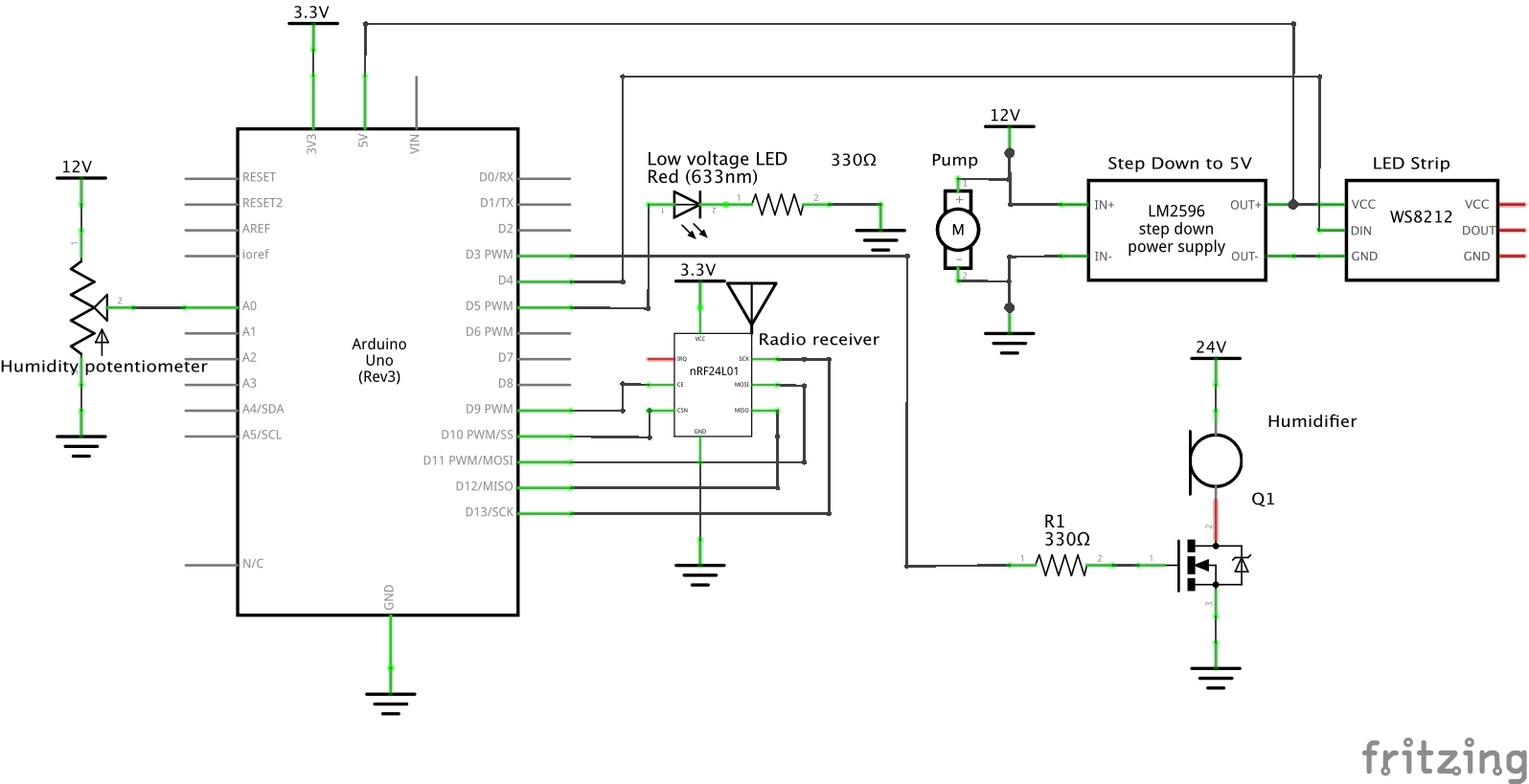
Main fountain module schematic
Remote fountain module schematic
The Schematic of the Remote Transmission Module. Uses a voltage divider to map the input voltage (normally > 5v) to a range that is readable by the Arduino’s ADC through pin A1 that allows it to detect low input voltages.
Comments are closed.