This purpose of this post is to document the different prototypes associated with the AutoBath. The AutoBath will allow Brenda to independently change the temperature and pressure of her bathtub using a remote. See previous documentation here: https://courses.ideate.cmu.edu/60-223/f2020/work/brenda-seal-team-one/
Mimi:
This prototype was trying to answer the question: how should Brenda control and change the temperature of the bath?
The final prototype for controls was a remote control that was 3D printed. The remote was modeled in SolidWorks. It includes an up and down button for temperature and pressure as well as a power button and an LED to communicate that the remote is on.
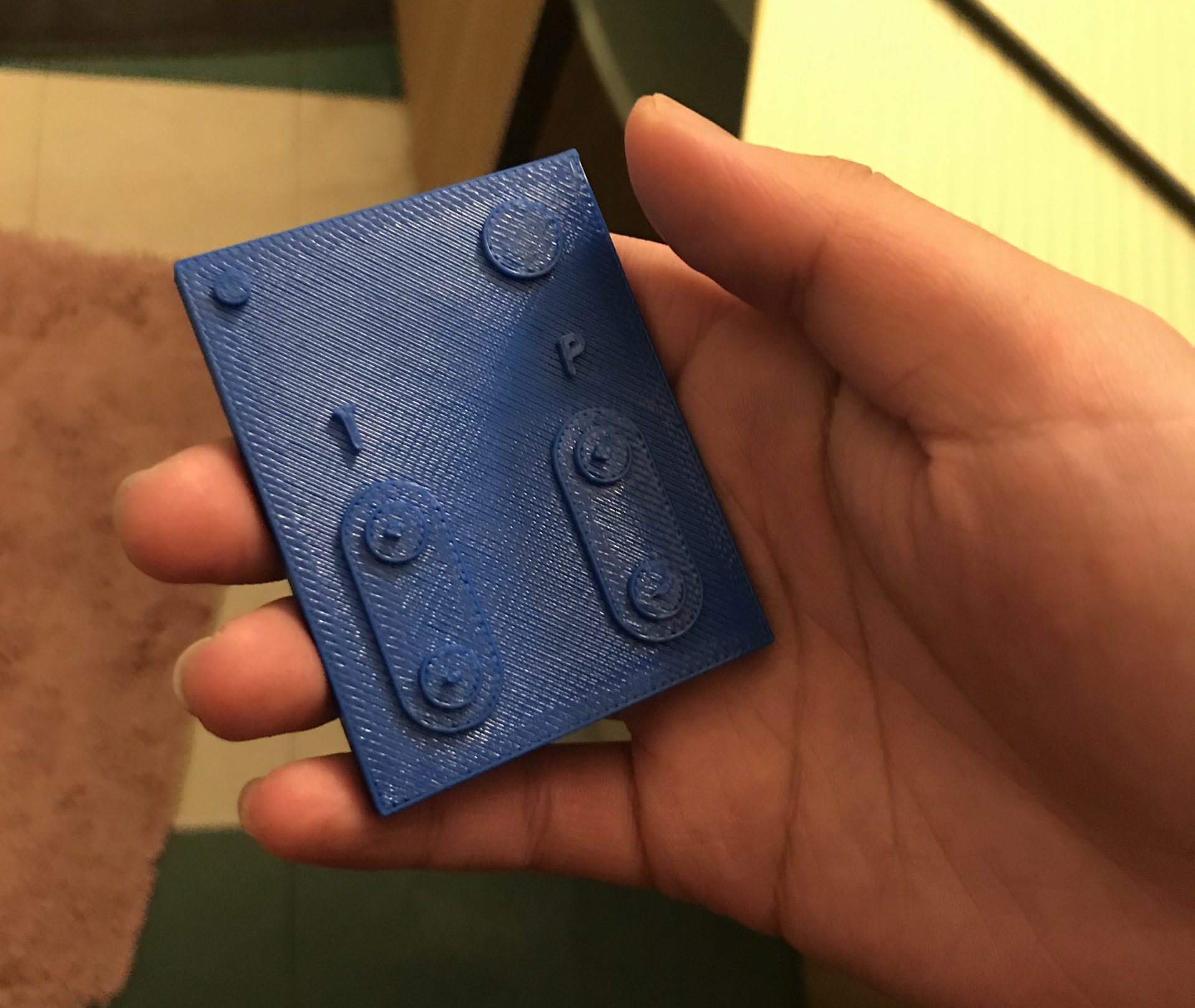
Mimi’s roommate holding the 3D printed remote while giving feedback about its design. Demonstrates how the remote fits in someones hand.
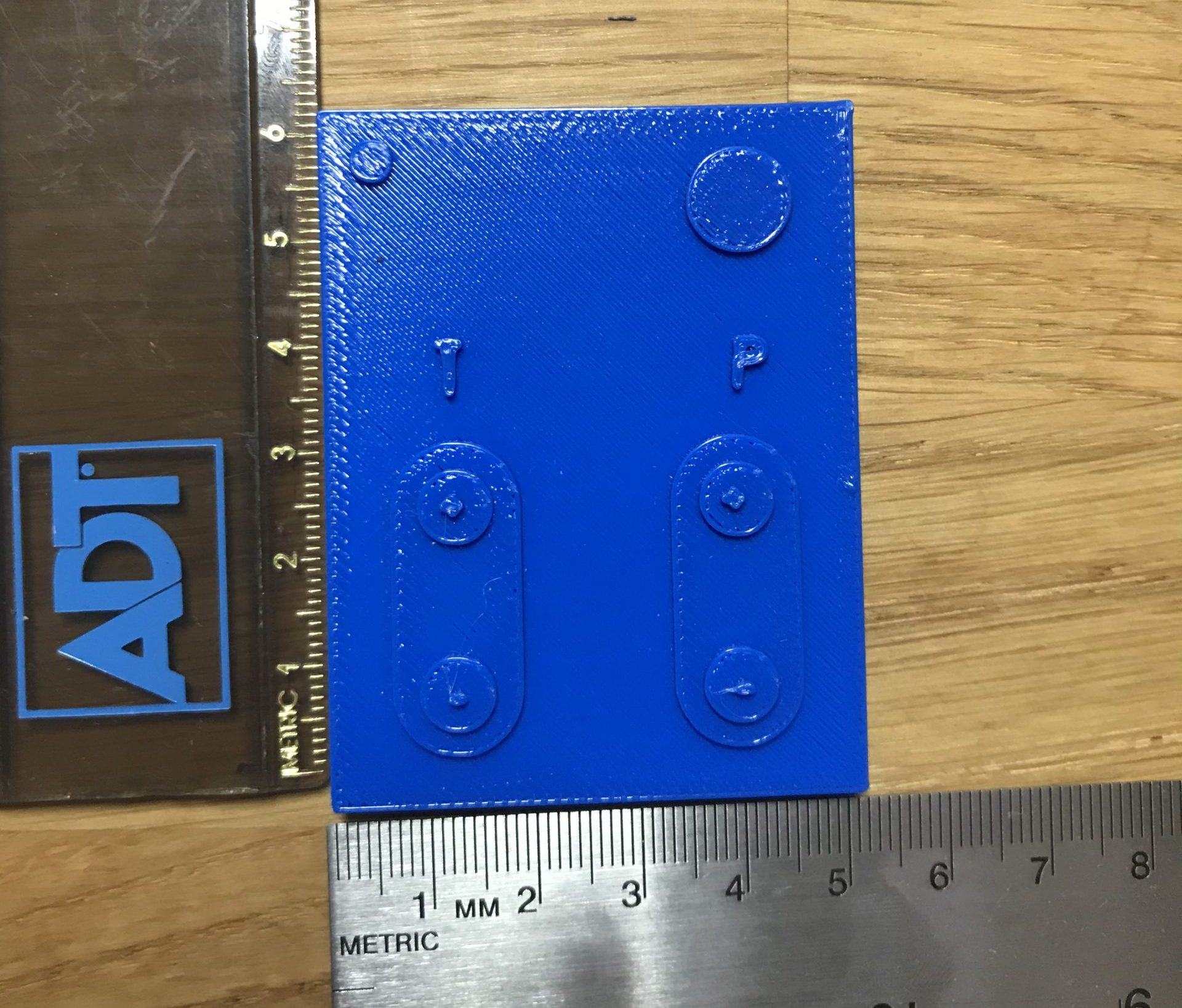
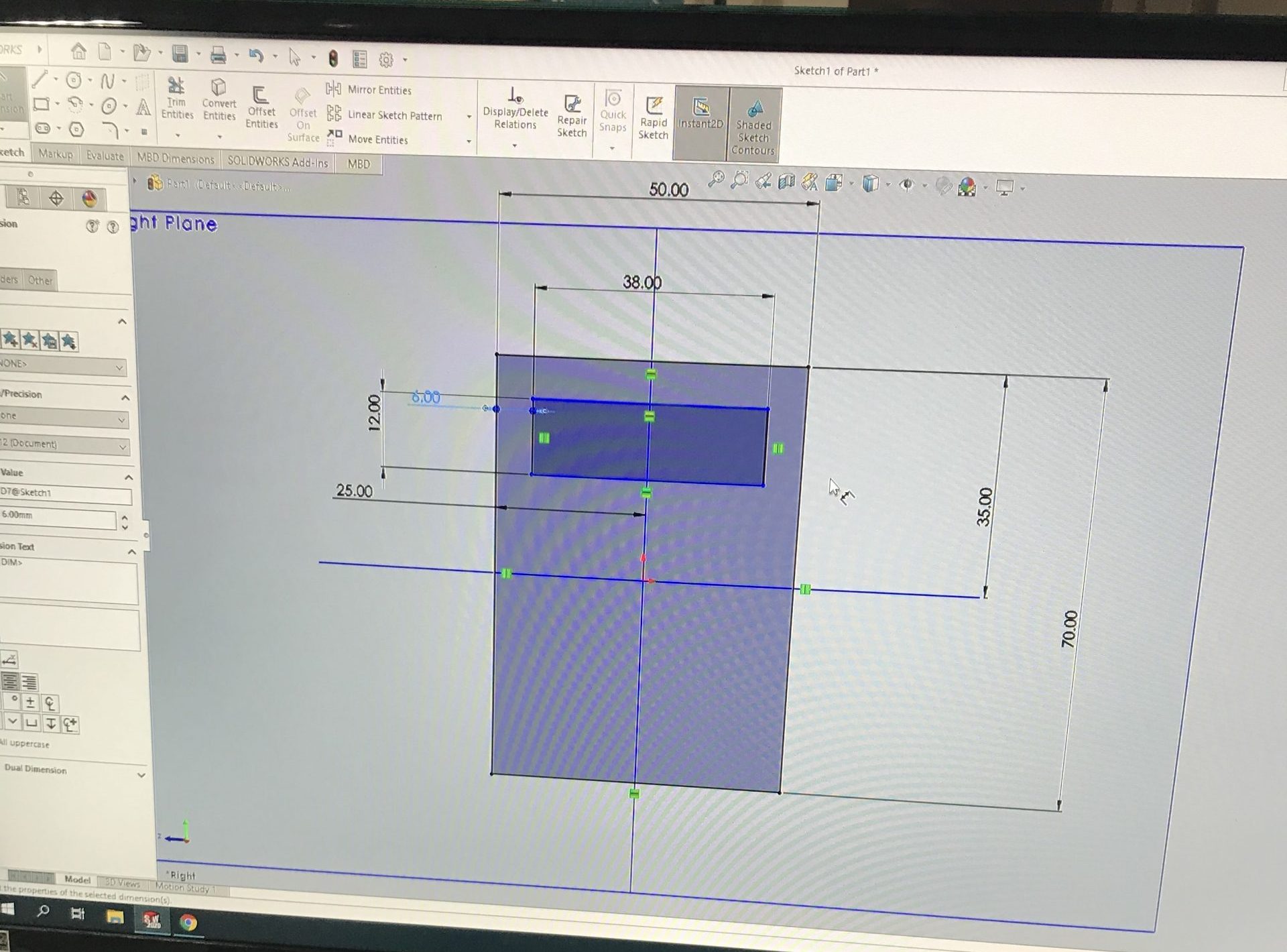
Shows the 3D printed remote is 6mm by 5 mm.
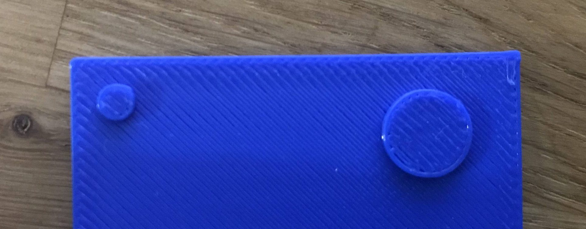
The top right circle represents the power button. The top left circle represents an LED that would be on when the remote is powered on.
Demonstrates how to increase the temperature of the water.
Process Images:
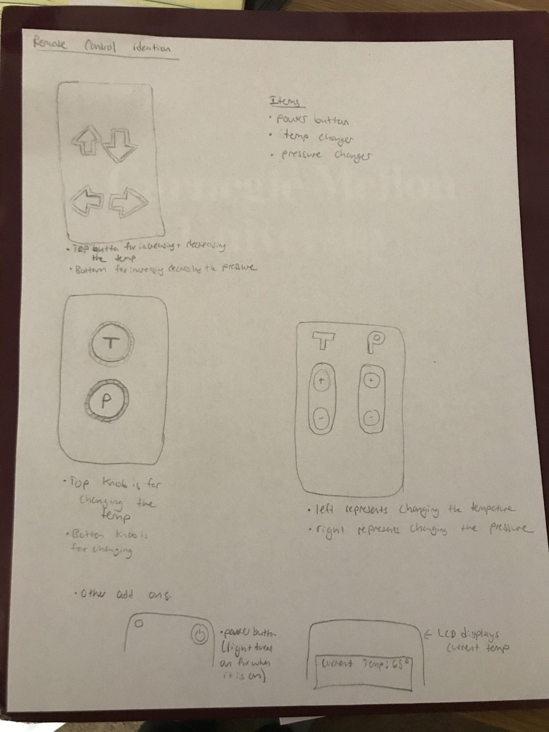
Sketches of possible layouts for the remote
A model of the remote with an LCD. After deciding to make the remote with an IR sensor, we realized we didn’t want an LCD on the remote.
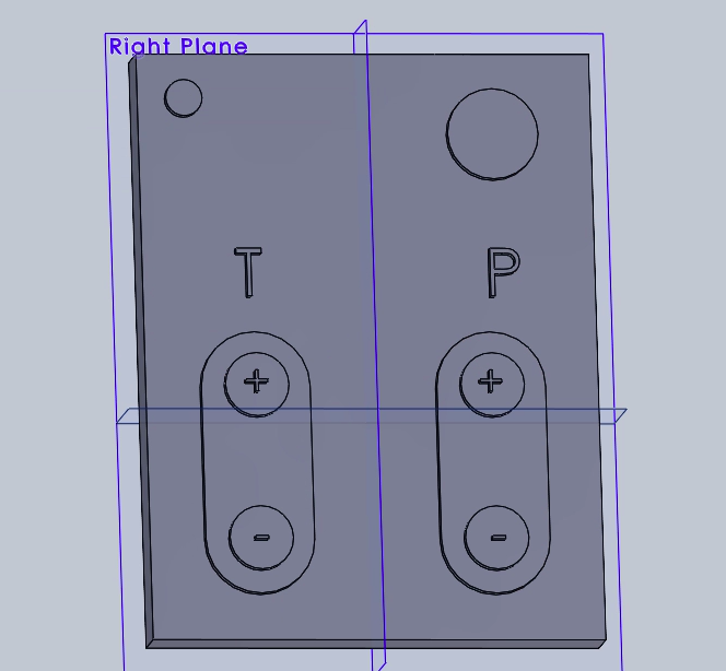
Screenshot of the remote control modeled in CAD before being 3D printed.
Thoughts:
The feedback on this prototype revolved around the ergonomics and the usability of this remote. For the physically proximate prototype presentation I showed the 3D printed remote to my roommate. Her feed back was that the remote was too squareish thus making it hard to hold comfortably. She also said it would be nice to have some sort of feedback to know how far you are turning the temperature knob and the pressure knob like you would have if you were physically turning the knobs. Lastly, she recommended the buttons be spaced out a little more to prevent the possibility of hitting the wrong button.
Brenda’s (our client) feedback was similar. She was not opposed to making the remote easier to hold, though it was hard for her to tell because she could not hold the prototype herself. She liked the tactile feel to the buttons and suggested making that more prominent because it easier for her to feel which button she needs to hit rather than see it. Brenda also suggested I think about the storage of the remote. She said it would nice if it could be attached to the wall or the side of the tub.
I will be attempting to implement all of this feedback into the the remote design going forward. The only surprising thing during the prototyping experience was how hard to it was to reconcile the dimensions on SolidWorks and real life. It was hard to tell how big the remote was going to turn out and feel when just looking at a computer screen. That made the 3D printed model more useful than I initially thought.
Carl:
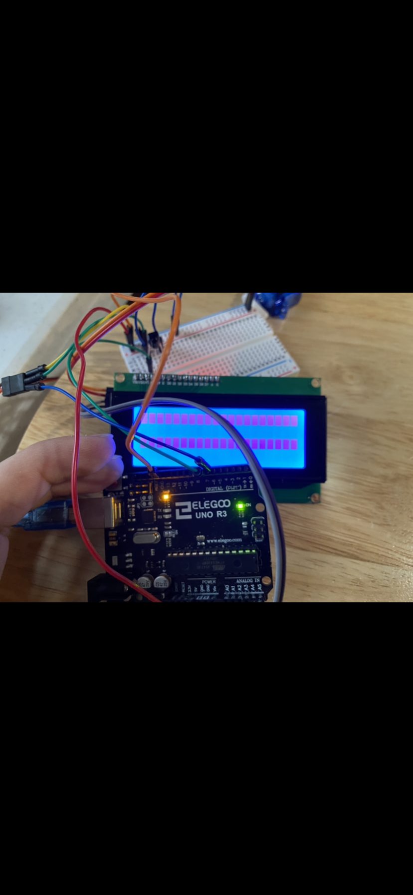
The question that I was trying to have answered was the physical demonstration of pushing buttons that would then translate towards moving a motor. The prototype itself was made up of a simple display screen, a motor tha has an input of angles, and a small sensor that is able to read infrared signals. The user would press a button and the motor would turn CCW by some degree that was adjusted from 0-180 degrees. “Pres” refers to “Pressure” as Brenda describes the temperature hardly changes, it is only the turning on and off of the faucet that is truly important. While both are important for the safety of the user, this was only a proof of concept.
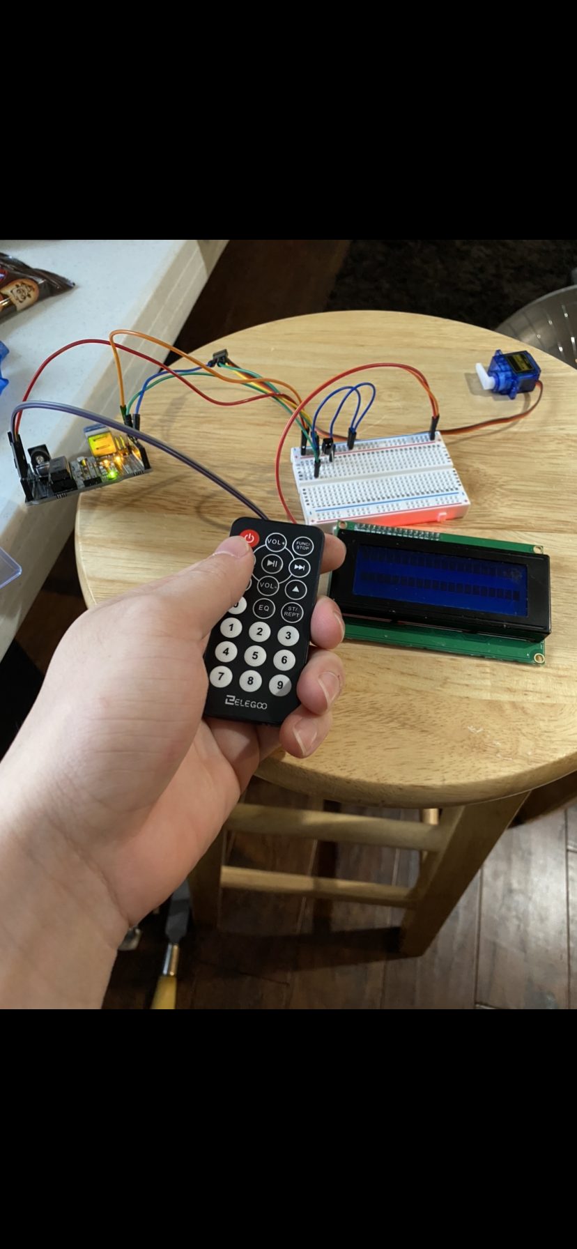
Shows size of remote in hand.
Shows the size of each component relative to each other. This is important because it shows the capability to design a small PCB that would be much easier for the future case for the device.
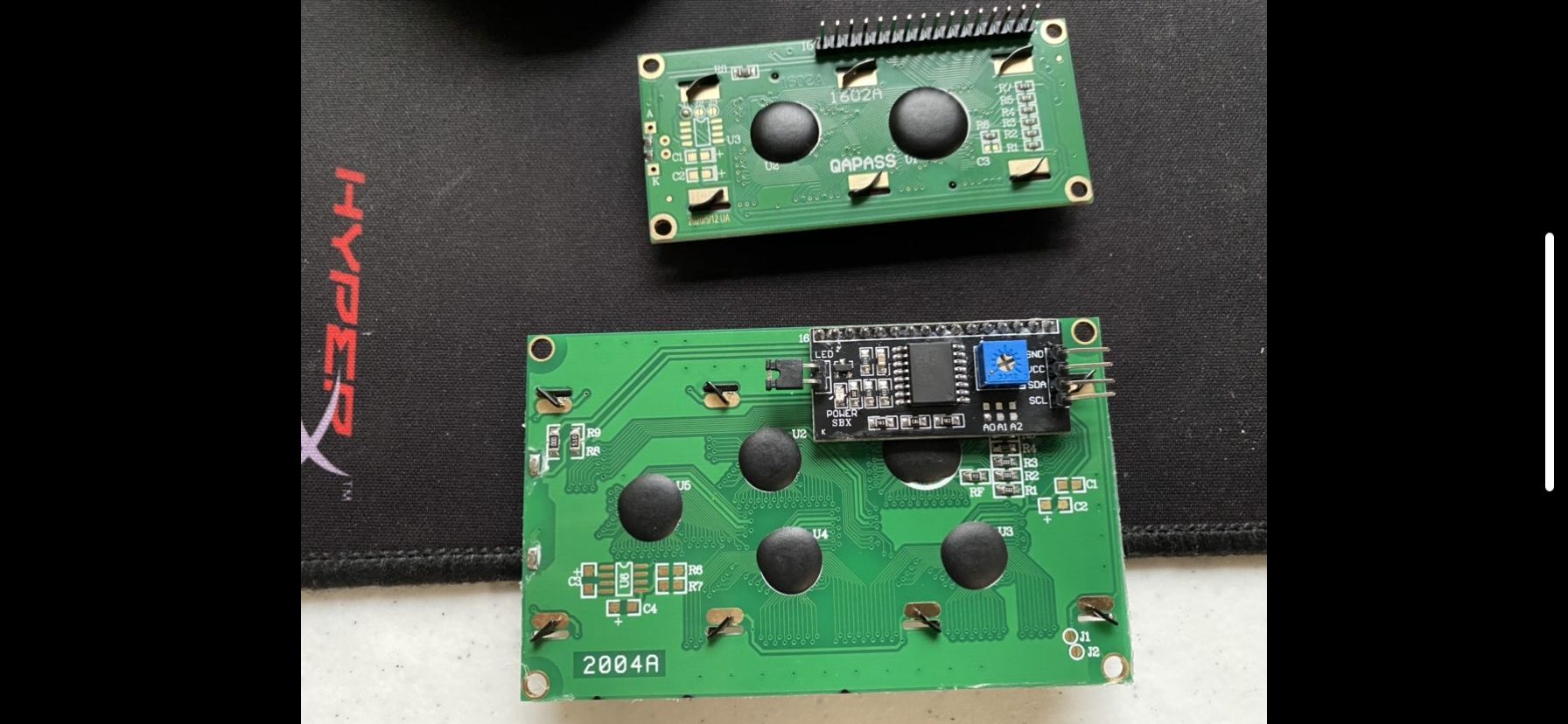
A big design choice was to go with the LCD I2C 20×4 versus the LCD 16×2 because of size and capabilities. Should alternate languages need to be used as well. This choice simply made the most amount of sense for the direction of the project.
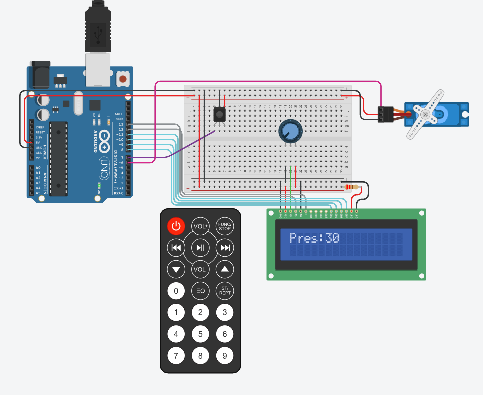
This is the TinkerCAD version of the prototype.
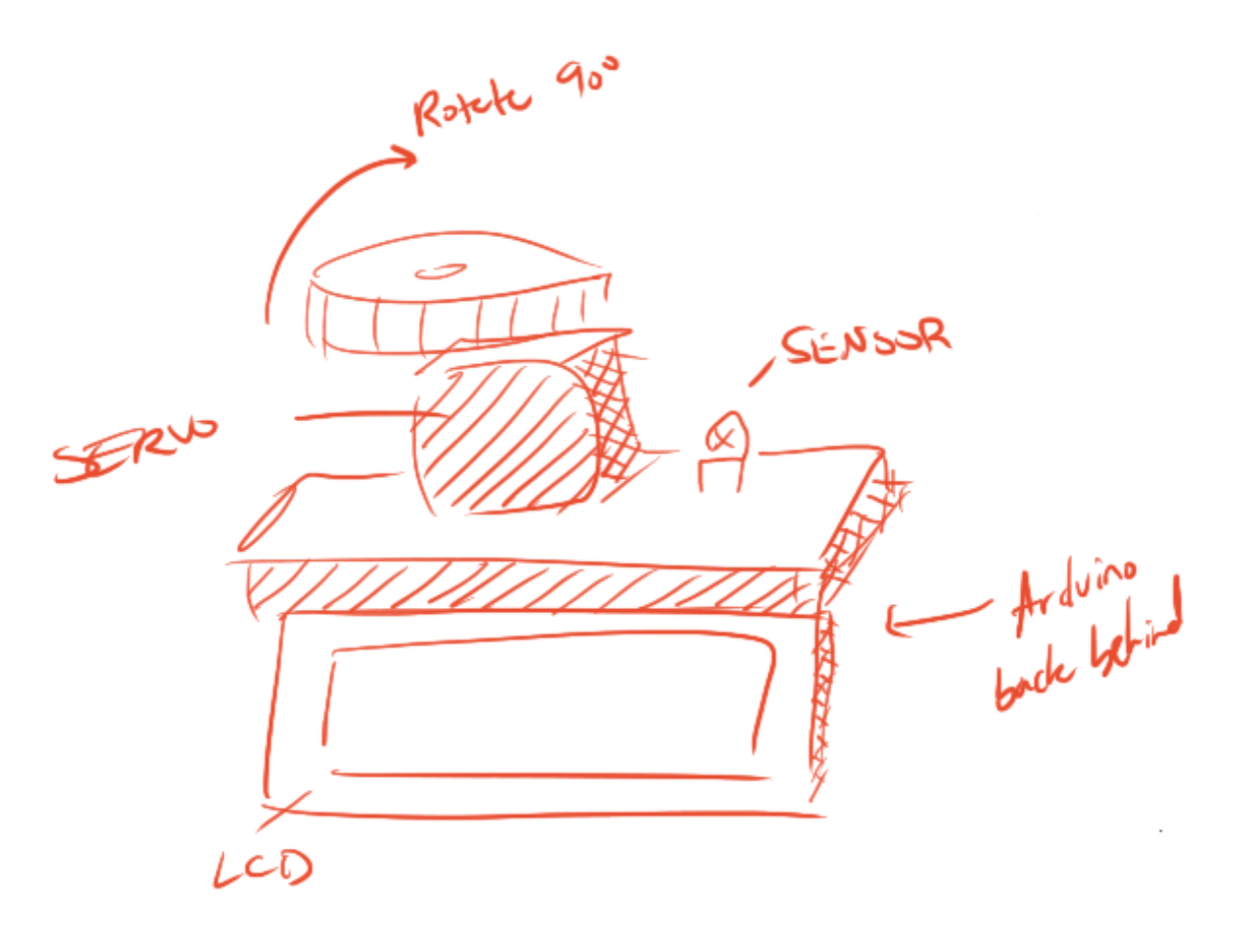
This was a rough idea for the design. It was just going to be sleek and compact. After the creation of the device, it makes more sense to use a PCB and then keep everything closed off.
This is the finished look. Thispicture differes because it is more focused on the final rather than the remote being placed in the hand.
Thoughts:
My biggest take away from this was the difficulty of designing the enclosure. Once the prototype had begun working, it was challenging to think of a next step. There were several components of the design that were contingent on being in the space and taking proper measurements and finding the structure that Brenda’s house would have been built on and so on. That being said, this prototype was a success for what it was meant to do. It was meant to demonstrate the simple capabilities of turning a motor when there was an input from a remote control.
The feedback that I receieved that I was looking more into was simplifying everything down, which touches into the design element of things. Where is the LCD going to be held? How is the sensor going to be waterproof? All of these questions that I had yet to think of. The feedback that was less insightful, and thus warranted not being taken, was more of the critique with the remote itself. This was the section that I was not going to be working on because of the work that Mimi had already undergone, so it was useless for me to consider those. Kind of like a trust thing where my partner was going to get it done regardless, and we can address that situation at a completely seperate time.
Moving Forward:
Overall, the prototyping part of this project went well for our team. Prototyping remotely was challenging at times but seeing pictures from Brenda was extremely helpful. We were able to get a working prototype for the mechanism that will move the temperature and pressure knobs and a working design of the remote that will control those functions.
For the remote prototype the next steps will start with a redesign of the remote in SolidWorks. The feedback from the in person and client critique will be implements to make the remote easier to hold and more tactile. Furthermore, some thoughts and research will be done to create a good way to store the remote. Also the electronic components of the remote will be modeled in tinkercad as if the remote was going to be physically made.
As for the motor mechanics, future steps then go into establishing a means for integrating the motor system into the physical bathroom. Because of the need for a more powerful motor, the final product would likely need to feature a stepper motor rather than a servo motor. Using the stepper would then require the use of a specific driver, needing a 12V power supply. This power supply is typically plugged into the wall, but that would make it a little bit more dangerous. Integrating a batter or a series of batteries would allow for this to work out a little bit better and narrow in on the number of moving parts. After a working model is created, the next step would be to optimize the entier system to allow for universal usage for potentially all faucet types. This would enable a greater marketability for the product as a whole to help impact more people’s lives.
In the future, it would nice to jump from the idea phase to the actual making phase earlier. We had our idea for our project pretty early but it took us some time to make physical, tangible progress with our idea. Once we started actually prototyping we ran into problems that we had to fix. For example, the remote prototype was originally going to be just a radio module prototype, but we realized it would be much easier to do a IR sensor remote. If we started physical prototyping earlier than we would have discovered and fixed these problems earlier leaving more time to work on our final prototypes.
https://docs.google.com/spreadsheets/d/1EqbDtPq6eH5k-xbRc-XUx_uFbc1yXL8K7nxA7on8S0o/edit?usp=sharing
]]>For the final class project our group, Team Amy, is working towards creating an art enabling device to help our client, Amy, draw on a canvas with greater ease and independence. After our initial interview with Amy – which you can read about here – we discovered this project opportunity revolving around art when she mentioned how uncomfortable her current method of painting or drawing is due to her needing to employ the use of a mouthstick. We came up with a few concept iteration sketches to explore how we may enable Amy to make art more comfortably and then had a subsequent meeting with her to discuss which ideas she believed would be the most useful to her and how we could optimize that concept to suit her level of mobility.
Based on this, our group decided to work towards an assistive device that allows you to draw through the use of a mechanical rig and arm-mounted controller device. When Amy moves her arm, the controller reads the changing position and then sends the position data to the rig, which then moves the position of the drawing utensil accordingly.
This post works as documentation for our prototype milestone, where we worked towards answering some key questions that we had in regards to this device’s functionality and overall user interactions. As each of our team members have a fairly different skill set, we decided to each answer a different question to cover more ground, as this is a fairly ambitious project concept, and play to our strengths. Dani, an industrial designer, decided to explore the controller’s ergonomics, as the controller would be the user’s primary interface with the device. Evan, an electrical-computer engineer, worked on the driving code which would provide the interface between the controller and the mechanical rig. Finally, Daniel, a mechanical engineer, explored how the mechanical rig itself would function to allow for drawing to occur.
The Prototypes
Prototype 1 – Controller Interaction
This prototype was meant to answer the question of: How might we create an arm-mounted controller that is simple to put on, secure, and comfortable to wear for a long period of time?
This particular prototype focused on the interactions that Amy would have to contend with to operate the drawing enabler device. This was done by creating an idealized “looks like” and “feels like” model of the controller out of light-weight, high-density foam and elastic along with a model of the mount the controller would rest upon when the device is not in use. I wanted to explore what proportions for the device would be comfortable to use for an extended period of time, the form factors the controller would have so that the direction you should hold it in is intuitive, and the ways in which Amy could put on this arm-mounted controller without employing the help of others.
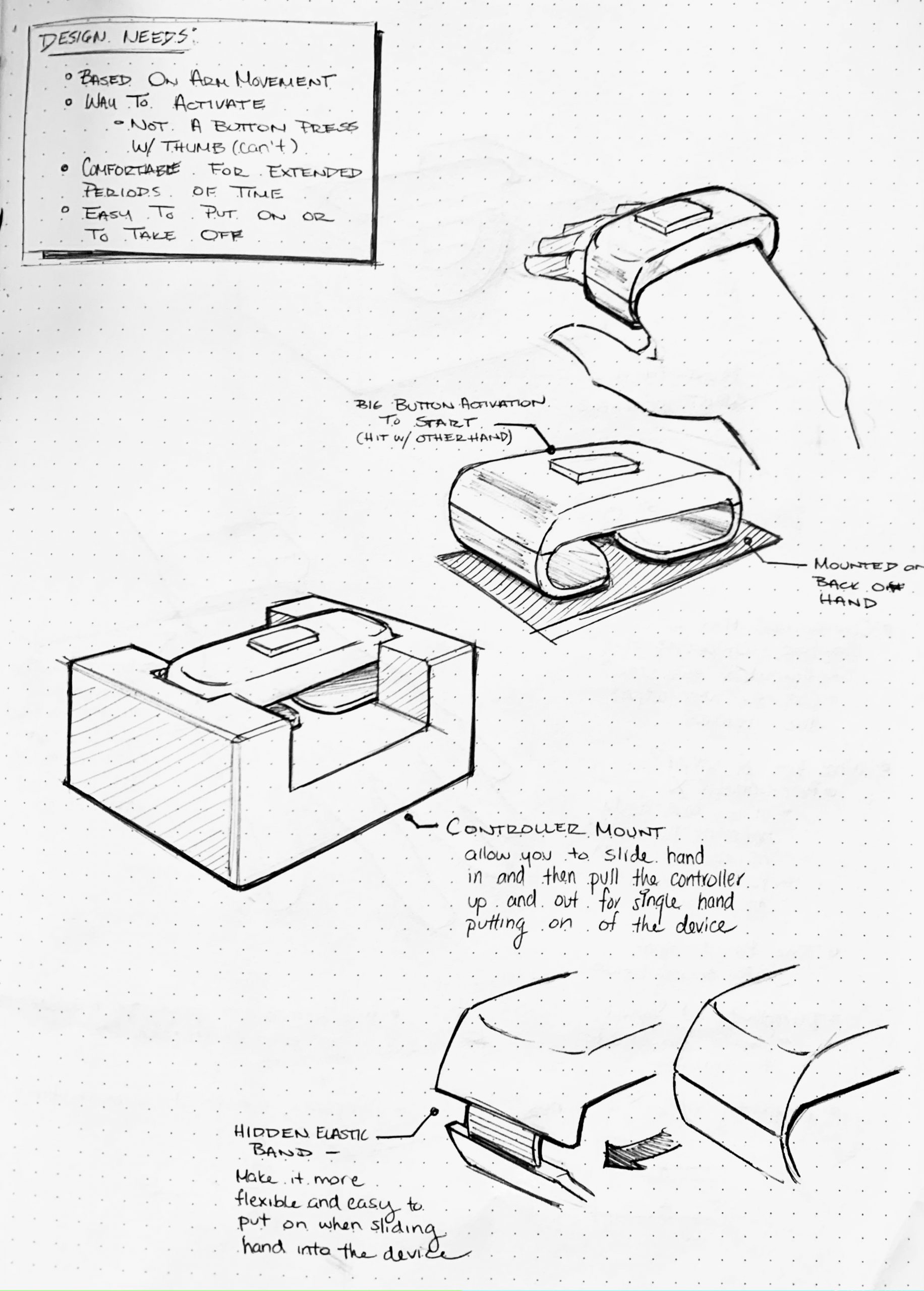
Sketches of the prototype concept to think through the different components.
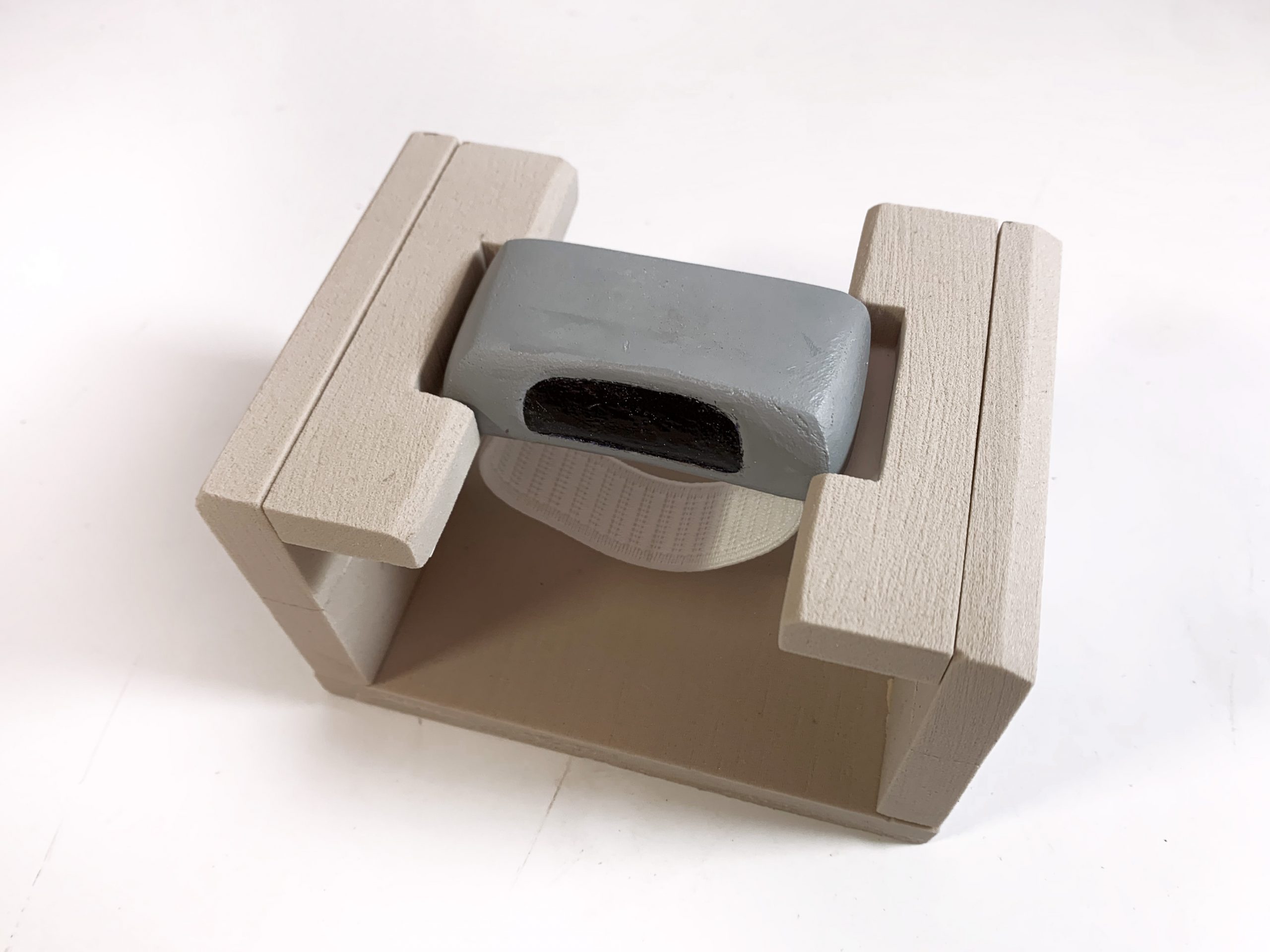
The arm-held controller in its controller mount
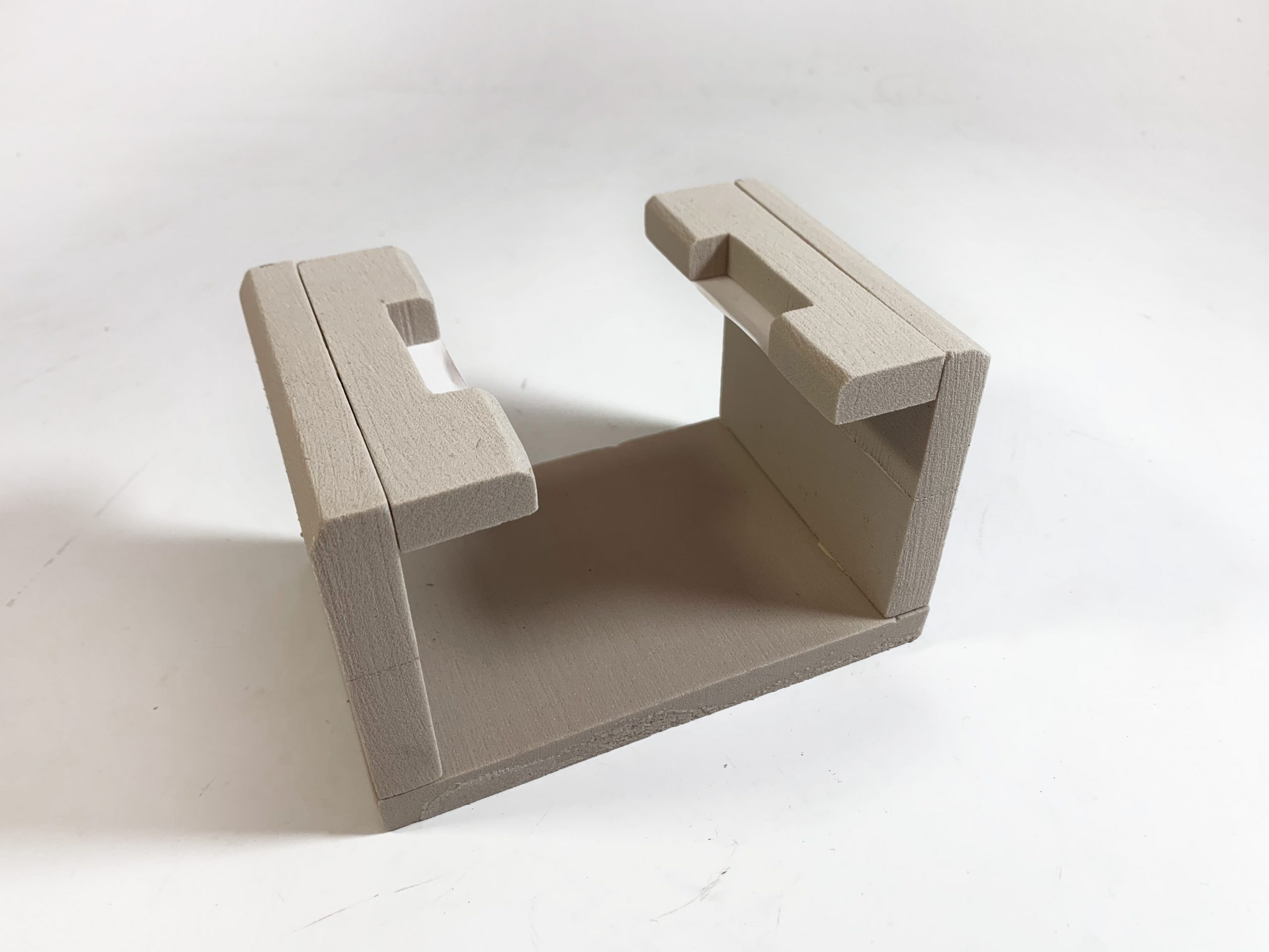
Controller mount by itself – has space to put your hand into and cut-outs to hold the controller in place
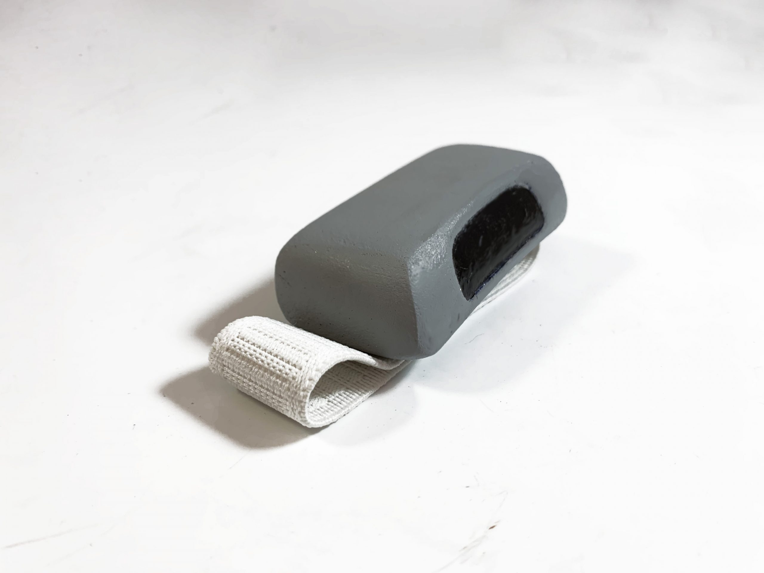
Controller by itself. The armband is a piece of soft elastic to make it comfortable and lightweight
“Wizard-of-OZing” the controller interaction
As demonstrated above, when the user is wearing the controller, their arm movements would dictate the position of the rig, which would then drag the drawing utensil across the canvas allowing the user to draw.
I tested out this device’s interactions by presenting the rig on the controller to friends and asking them “how would you put on this controller by only using one hand?” and then seeing what they did. Through this process, I discovered that while people understood the overall interaction that I was hoping they would (where they stick their hand into the controller’s band and then lift up to release it from the mount), the interaction was a bit awkward as the holder was too narrow to comfortably allow for all hand sizes to lift out.
A prototype test leading to an awkward interaction
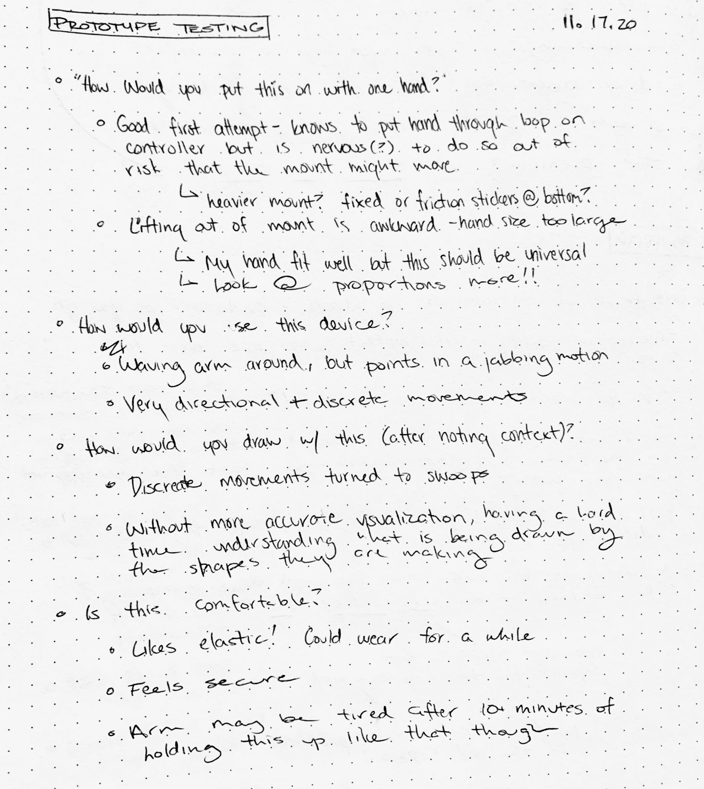
Notes from prototype session
Through the creation of this prototype, I learned that while people understood the overall interactions they would have with the device, some of the particular dimensions were a bit awkward and hard to transition into. Furthermore, through the testing, I learned that while the controller itself had a comfortable design that people noted to be suitable for its purpose, the action of holding your hand out for so long without any support may grow to be tiring very quickly – especially for Amy who is still working on building up her arm muscle strength. This is a design flaw that we, as a team, later discussed and are currently working on reconsidering (more on this particular note, however, will be in the next steps section of this documentation).
Furthermore, this current prototype works under the assumption that we can achieve a similar controller-to-rig communication as a Wii remote by employing the use of two MEMS accelerometers and an infrared sensor for position triangulation but this will most likely not be the case. We are currently working through alternative sensor options to make this controller-to-rig communication more accurate, which in turn implies a redesign of the general controller interactions based on the inputs the new sensors would require. Overall, while this prototype did work towards answering the question ” How might we create an arm-mounted controller that is simple to put on, secure, and comfortable to wear for a long period of time? “, as it showed that people did understand how to put on the controller and then use it, there are still further edits to be made to the design to ensure proper functionality and a comfortable, non-tiring experience for arm-controlled interactions.
Prototype 2 – Mechanical Brush Holder
Different from the previous prototype, this prototype was meant to answer the question of: How can we give free 3D-movement on the brush by using motors?
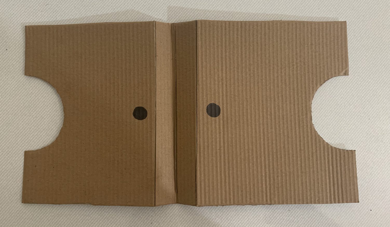
This particular prototype focused on the physical movement of the brush that Amy would like to move. The basic idea was brought from the 3D printer’s structural model. Since there were limitations with the materials for this prototype, I used cardboards to demonstrate how the structural parts will move in order to achieve the free x,y, and z-direction movements.
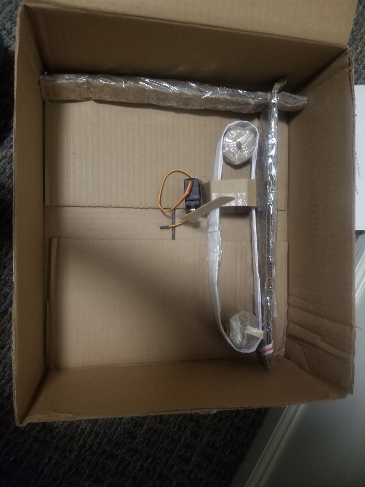
General Overview of Mechanical Rig Prototype
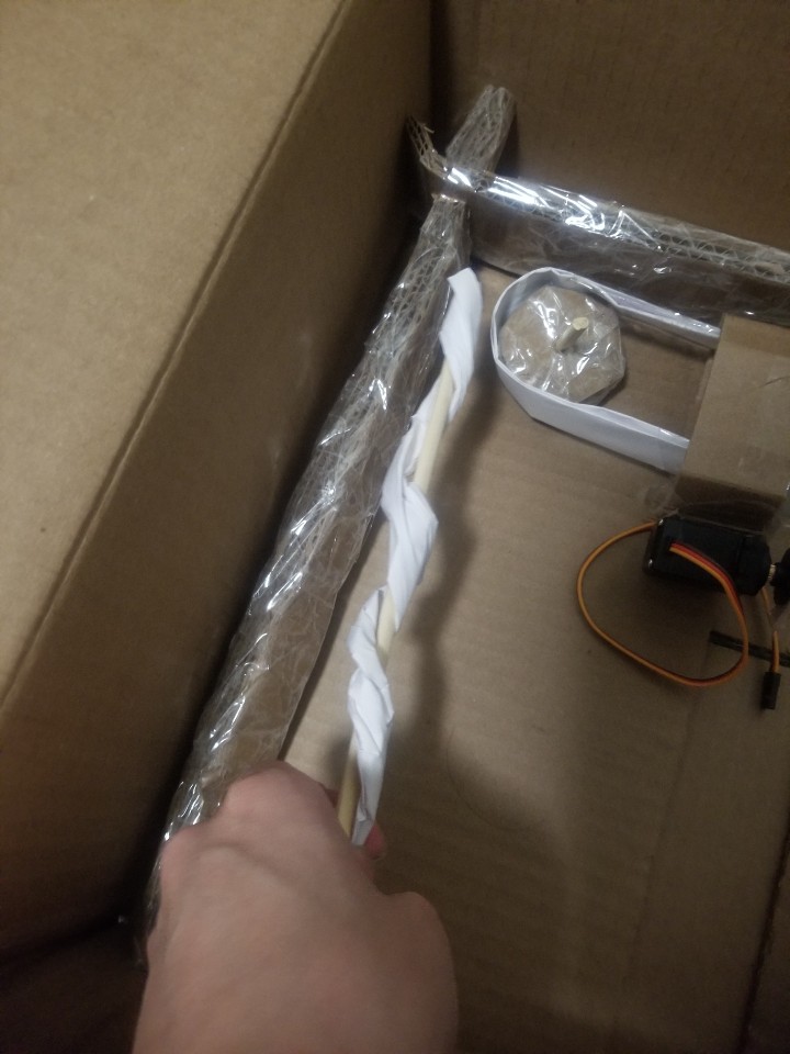
The threaded bar section of the prototype. (This will control the y-axis movement of the machine)
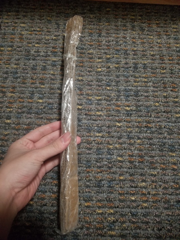
Since the top general picture will be hard to understand, here is a part I may use for this section of the prototype.
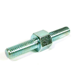
Threaded Rod From google
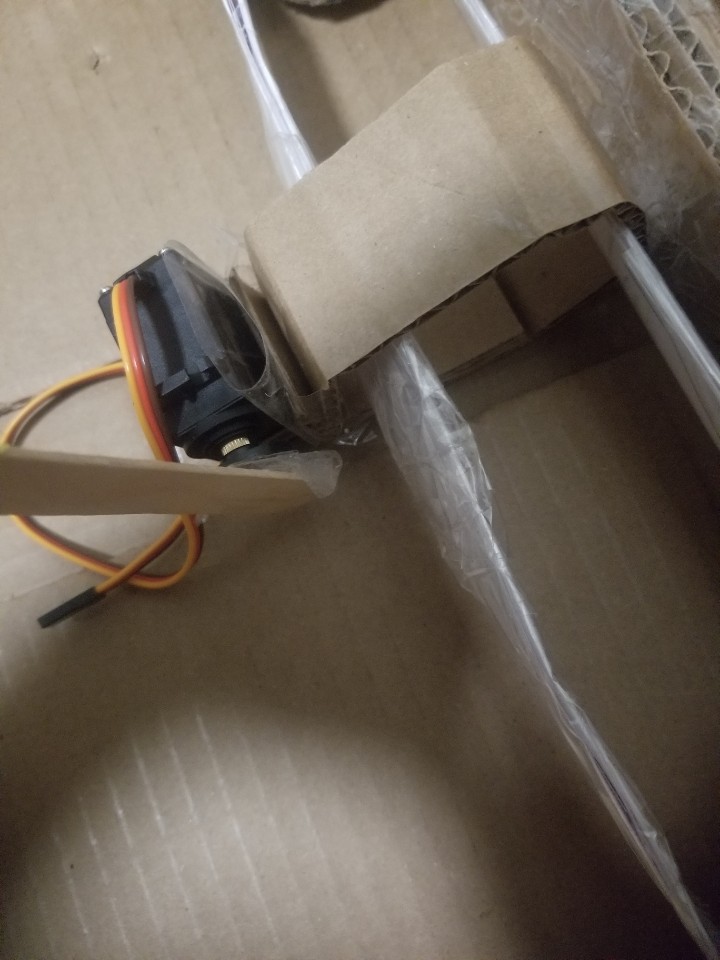
The Servo motor will control the z-direction of paint brush motion.
Basic Idea of how the machine will work. (Since the prototype is made with cardboard, it breaks easily.)
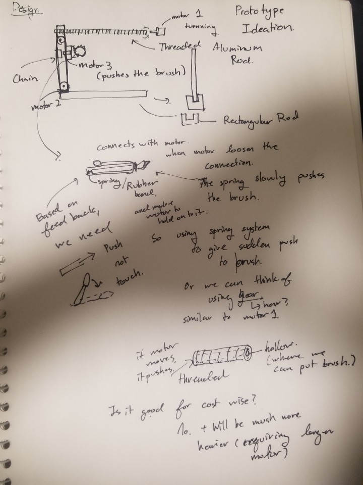
Ideation of Prototype and detailed plannings for each Mechanical Sections
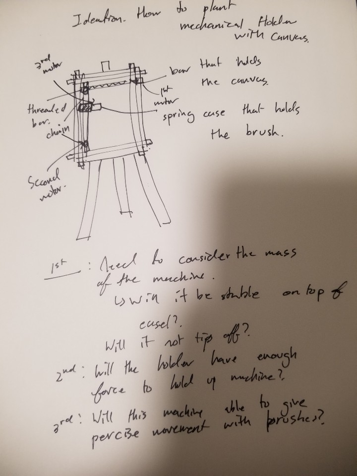
Ideation how to plant the Prototype ideation into Actual use. Brainstormed some limitations that might come while I am building this.
Failed Prototype for motor 1 Mechanical Section. (Tried to demonstrated threaded Rod by twisting the cardboard but it failed because it did not have enough force to handle that twisted shape. If we see carefully, we can see the twisted shape on the cardboard.)
So instead of just making a threaded rod, I brought an image from google to give a better understanding of how my parts would be shown.
During this prototyping process, I was surprised that the free x,y,z movement rig requires a lot of custom parts. At first, I thought it would be easy since there are many samples like 3D printers or robot arms that can rotate freely around the 3D space. However, after deciding to draw and plan the prototype for this mechanical movement rig, I realized that most sections require specific parts such as chain and threaded rod to give rotational motion around the rig. As a result, I was not able to get most of my parts before the prototyping since most of the parts need to be precisely custom made based on the planned model.
Also, during the presentation, I got feedback about the z-direction movement of the brush for this prototype. In the prototype, I used a servo-motor to give a slight touch of the brush on canvas. However, after the meeting with Amy, she told me that she needs to control the brushstroke by changing the pushing force of the brush. As a result, I might need a slight change with the idea for z-direction movement.
Prototype 3 – Driver Code/Smoothing
The goal of this prototype was to test some code to smooth the movement output by the arduino regardless of the input. That is, it was meant to ask the question “how do we account for errors in measurement and extra unintended motion to allow for a smooth stylus experience even without as fine motor coordination for the task?”
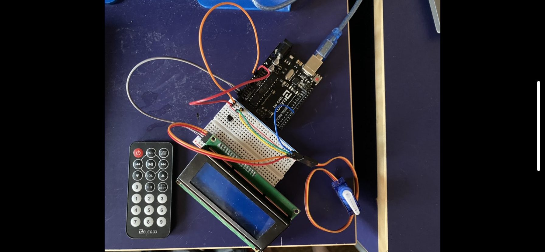
This prototype focused on the functionality side of the project and is rather simple to boot. It is not intended as a prototype for anything but the software, hence the fully simulated input and output. It’s merely a joystick wired to an arduino. From there, the arduino merely sends a message to unity which is then parsed and turned into a position. The final version would instead rout the output to electrical signals to control the motors.
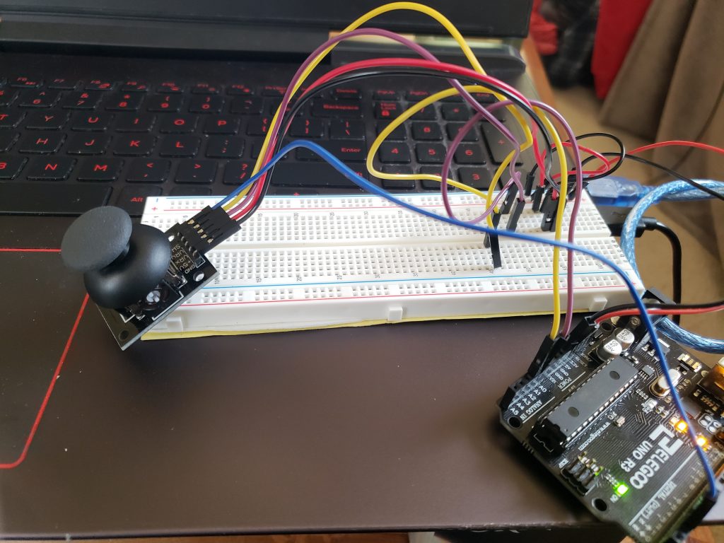
The full prototype wiring setup – nothing very fancy.
Video demonstrating prototype in action. The olive green dot is the cursor (I couldn’t get the color to improve sadly, as I think I was using the wrong render settings).
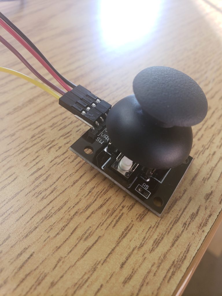
The thumbstick component up close
My findings in prototyping was that the smoothing had a mild effect on the motion, but otherwise wasn’t super noticeable. In general, the prototype really failed to answer many useful questions as it really only simulated the input and output, and poorly at that. Without the finalized input, its effectively impossible to expect any trend in the motion – there might be noise that’s unique to the control apparats. Additionally, the output, which is a mechanical rig that receives the input after smoothing, could have its own share of mechanical difficulties that can’t be easily accounted for, like perhaps max safe movement speed.
Other than the rather exciting revelation that unity can talk to arduino, I suppose I was a little surprised to learn just how little you can learn about the utility of control software without actually having accurate, or even mild approximation of inputs. In simulating, it was found that there isn’t a noticeable difference between the smoothed motion and the unsmoothed motion, and that could be for a whole variety of reasons that could vanish once the software sits between hardware components operating in a real space.
Without seeing how something like a brush or a pencil is controlled by the rig and software, its a hard call to say that the prototype’s findings could be useful.
MOVING FORWARD
Our team learned a lot about what we want to make through the prototyping process, both through the answering of our initial questions and the raising of new ones. After the prototype presentations, we were able to talk about where we were to Amy and discuss her questions and concerns. Based on this conversation, we realized that there are many nuances to the painting or drawing experience that we had not yet considered such as: how do you switch drawing utensils easily? can you adjust the pressure of the utensil? is there a way for the user to change the scale of their movement to the output of the rig? With these questions in mind, we decided to simply where needed (perhaps a pivot towards a “drawing machine” rather than a “painting machine” as that requires less changing of paint colors and wetting the brush) and potentially add an additional switch box device which can let the user control the scale of their movement to output and the pressure of their utensil (low, medium, or high). We are currently working towards finding what is a proper level of ambition in these added components and what we should consider being out of our project scope.
We also experienced some of the challenges that can come with remote collaboration – it can be hard to coordinate schedules between the team and with our client so meetings to discuss progress and work have been a bit difficult to set up. Nevertheless, working through the process of these prototypes has taught us to make sure to plan our meetings well enough that we can hit all of our action items fairly succinctly during the meetings once we are able to find some overlapping time. The creation of our final work plan has also really helped in establishing deadlines and overall team alignment on the project schedule.
Overall, our prototypes have helped us to better understand aspects of our project that we had not even considered and establish new questions that we are working towards answering. With this, we can begin to work more concretely towards our final project and are excited to see how it all turns out when the different aspects of it all come together!
]]>After interviewing with Elaine, we were able to start the prototyping development to help us better understand our initial device concept. You can see our documentation about our interview process to learn more! We were able to truly connect and better understand a day in Elaine’s life to try to create a device that would be of convenience. Upon thinking and discussing as a team we were able to come to a final prototype concept with a direct problem statement.
Our client enjoys music which is evident through their theme songs consisting of Mountain Lions by Lonestar and many other classic songs! However, Elaine has difficulty with devices that require the use of grip force and strength, so there are musical instruments that are difficult to use. Elaine suffers with Larsen syndrome, Adams-Oliver syndrome, and Ehlers-Danlos syndrome. These disabilities causes here to not be able to extend her arms fully with her right arm (only 90 degrees). In addition she is missing muscles in both shoulders (deltoid) while having her joints be loose and unstable due to lack of collagen her body can properly make. Lastly, her left hand only has her first bone on the thumb and her right hand is missing most of the thumb muscles. She emphasized that there are times where she uses her mouth in place of her hands. We decided to work with Elaine to build a musical device that would cater to her needs by having flexible inputs while ergonomically focusing on her personalization.
This documentation is meant to help us summarize and reflect our prototype process and journey to find our next steps and any other problems we found on the way! Because we come from various ranges of backgrounds, we decided to split the explorations based on our strengths.
Prototypes:
The three paths we decided to take for this exploration were ergonomics, design, and software. The goal with looking into the ergonomics of the potential prototype was used to find solutions to make interactions more comfortable and increase productivity which would be applied later in the design. For the design, we used this experience to have a better understand of what are the best design possibilities. Lastly, with software, we wanted to double check that the electromechanics that we thought of in our design prototype would be possible.
- Ergonomic: What is the most comfortable range of motion to build for? How can our physical artifact be best tailored to meet Elaine’s specific needs?
- Design: Does a user understand how to use this without being given verbal instructions? Does our design help with the constraints in mind or make the experience more difficult?
- Software: How well does the MIDI interface work with the Arduino and does the sound it creates resemble a musical instrument enough?
E R G O N O M I C S
Simply put, form needs to follow function. We knew that the instrument should be tailored to Elaine’s unique abilities. The interactions which manipulate sound should not only be engaging, but also comfortable to use. If done right, there will be very little in the way between Elaine and the music. Elaine is able to extend her right arm to 90 degrees, while her left arm has a full range of extension. However, she only has a full hand on her left arm, while her right hand only has the first joint of the thumb. Explorations needed to be done to better define these needs. Which directions of motion are most natural? Are there positions which can be sustained longer than others? What touch points best satisfy comfortable movement while maintaining the magic in sound manipulation?
INITIAL PROTOTYPE DEVELOPMENT
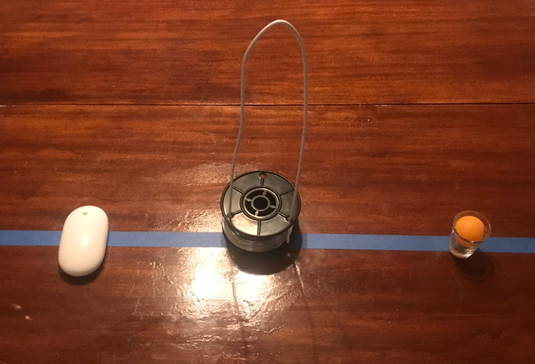
Initial arrangement of different interactions with household objects: magic mouse, coat hangar “theremin”, and shotglass roller ball
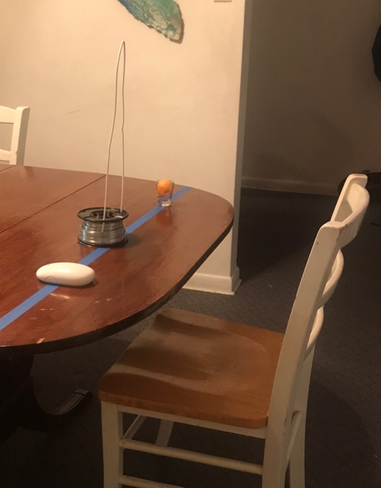
The choice of this table was intentional, because of its spacious overhang lending itself practical to wheelchair use.
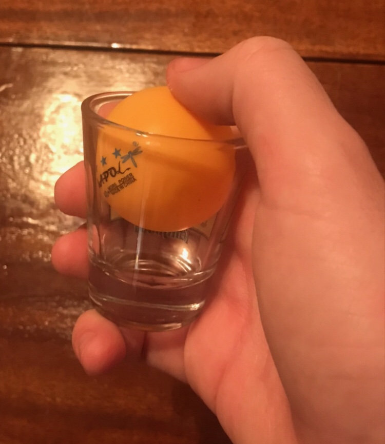
A very pleasant discovery was how a ping-pong balls snugly rolls in a shot glass, used in place of Elaine’s favored ball mouse.
IMAGES OF PROTOTYPE TESTING
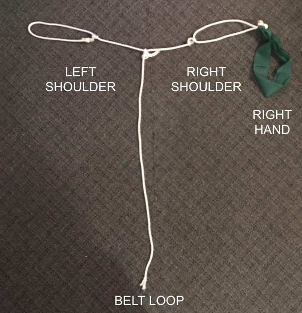
In a prototype shift, I zoomed back from the interactions to better understand Elaine’s conditions untethered from specific context. To do so, I made this wearable out of rope and an exercise band to restrict my movement.
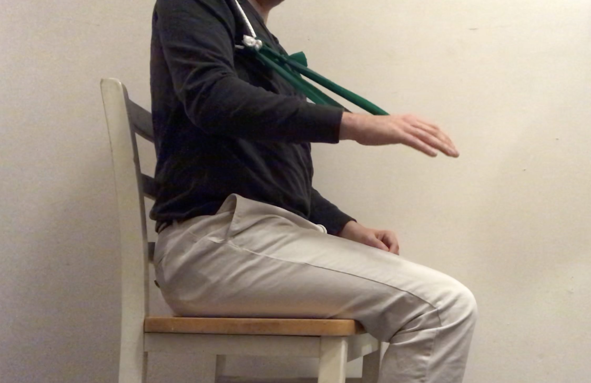
Profile of the band at its fullest extension with a resting arm
I found that the farthest extension which is not fought with resistance is about 70 degrees in, understandably short of the maximum.
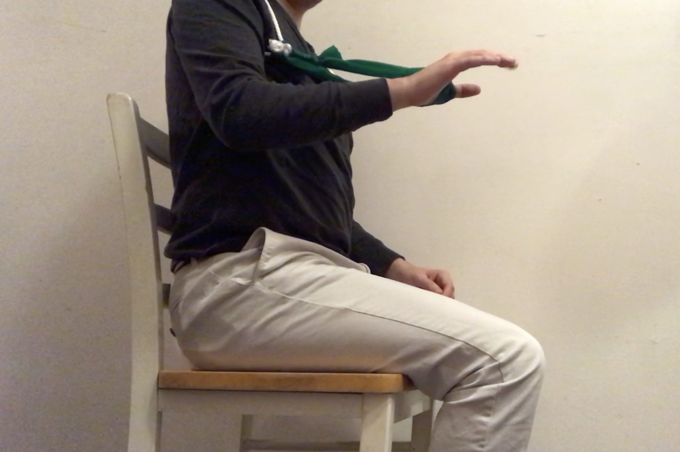
CLIP OF PROTOTYPE TESTING
Here is some general arm movement to play with the vertical and horizontal resistance in the device. Horizontal movement was the easiest.
CONCLUSION
The prototyping process was enlightening. Having started with specific touch points in mind, I enjoyed finding lo-fi ways to a diverse set of interactions. I believe that this initial presented some great moments for decision making, even down to where I was going to set up these interactions. Of the three touch points, the theremin predictably held up to being the least demanding interaction. However, I ultimately felt I was getting ahead of myself. These prototypes set the stage for questions, but the experiments were only really for someone with my own abilities. It defeats a lot of the purpose of the project.
Instead, I zoomed out. Building the simple harness to limit my range of motion brought me closer to Elaine’s lived experience. Just experimenting with the exercise band challenged a lot of my assumptions. Sure Elaine could move to a 90 degree extension in her right arm, but the band made it apparent that there is no need to max this out. The edge out any range of motion is usually not the most comfortable. Additionally, the horizontal range of motion became super apparent as something to leverage. In playing with the exercise band, my arm pivoted left to right with ease in contrast to the resistance in its vertical movement.
Elaine’s feedback built off of these insights. She noted that gravity is not on her side, given the extra weight it puts on her scarce tissues. Once her arm is on a certain plane, it is easiest to keep it there rather than dip up and down repeatedly as I did. Another blind spot in my experiments is still in the horizontal movement. Elaine notes that it is easier to move her right arm left to right, but noted there is some strain when reaching directly in front of her. Moving forward, these insights point to this instrument potentially being in two pieces to customize comfort and minimize hard to reach interaction.
D E S I G N
This prototype was designed to help figure out the design options to cater the most efficient and best experience for Elaine. The question in mind were Does a user understand how to use this without being given verbal instructions? Does our design help with the constraints in mind or make the experience more difficult? These questions were based off of our prototype concerns that we were unable to figure out when brainstorming through sketches.This was done by creating simple prototypes through cardboard and paper while using the Wizard of Oz method. Before starting all of that, I wanted to evaluate the main goals and concerns the prototypes are meant to deal with. I was able to do so by writing down everything and then decide on the next steps of the process. Personally, regardless if what I write down is helpful and accurate, I prefer to write and think out my thoughts and possibilities to see them all and then move onto the visual iterations.
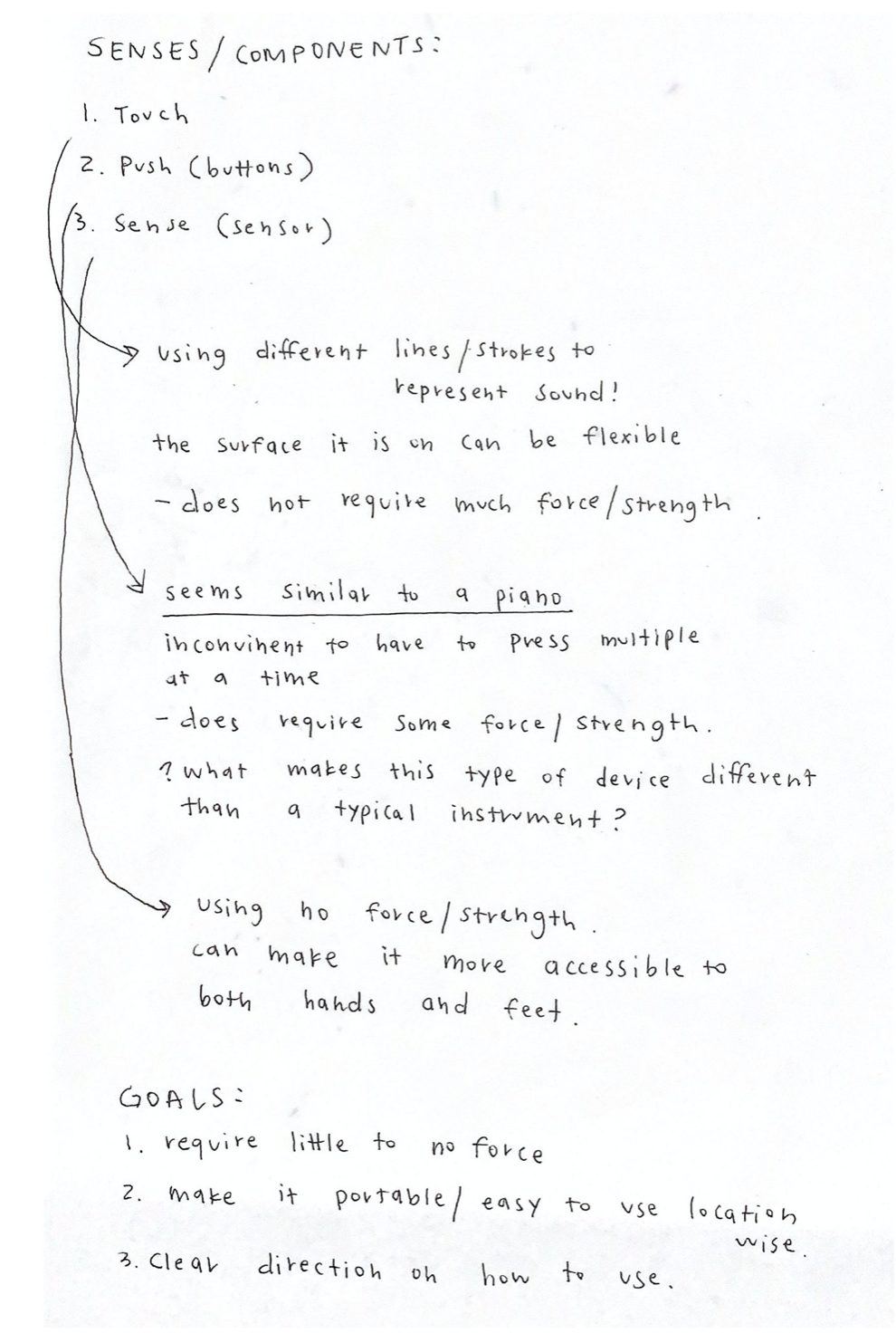
Here are the notes that I took in order to start the design iterations.
INITIAL PROTOTYPE SKETCHES
The particular prototypes focused on the interactions that Elaine would have through using touch and sensing as inputs. While considering her settings, we explored ways to make the potential device be flexible. For both iterations, they have two inputs: the volume and tone.
With the first iteration concept, I explored the idea of using electrical tape or electrical paint to be used as the input touch navigation. While trying to make the pattern of the shapes intuitive while allowing users to know that there are changes as you move through them was a thought that I still continue to think about and iterate. The purpose of exploring this touch method was because of Elaine’s emphasis that she prefers to have this device use non-force touch or sensors. We discussed buttons, but she mentioned that it is more difficult to do.
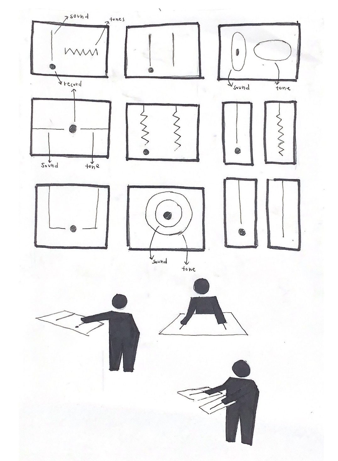
I tried creating various patterns to iterate on the touch base prototype iteration.
This is the second type of device iteration that focuses on using sensors as the input for sound and tone. The left side is mainly used to manipulate the volume while the right side is using the tone of the instrument. While iterating, it was initially focused on only being used by hands, but knowing that Elaine’s feet are useable, I tried looking into how to integrate both parts for this device through proportions. In addition, understanding if we want this device to stand or lay on the platform.
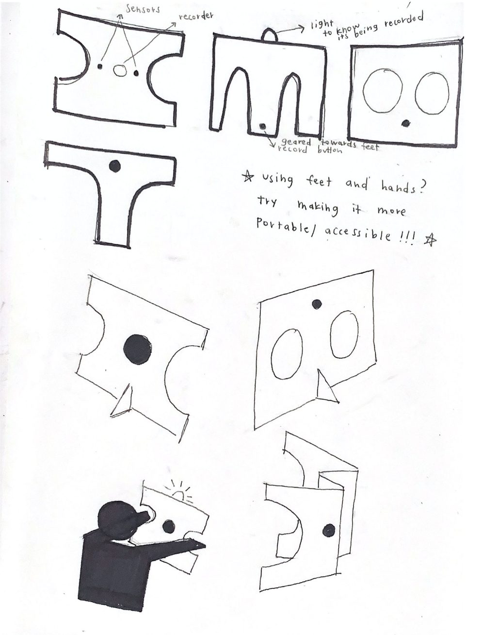
Here are the second concept prototype iteration sketches.
INITIAL PROTOTYPE DEVELOPMENT
From the sketches, I was able to prototype the final iterations with cardboard, paper, and a black marker. The first iteration is focused on the use of touch to manipulate the inputs. The cardboard is the speaker element and the black lines and shape is used for the touch buttons.
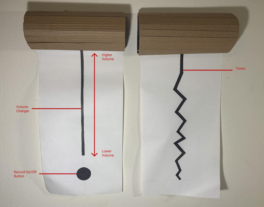
This is the mapping of the components of the first iteration prototype.
This gif shows the record on and off button.
Here is the user interacting with the volume.
This gif shows the interaction of the tone input of the prototype.
The second iteration is focused on the sensor. It is foldable so that Elaine is able to flexibly carry and use the device. One of her wants was to have this device have multiple inputs to allow her to use it anywhere with most devices. The left cut out is used to manipulate the volume of the input while the right cut out is used to change the tones of the instrumental sounds.
Here is the design flat down. The creases are used to allow the device to be foldable flat so that Elaine can comfortably more around.
Here is the prototype standing up!
PROTOTYPE TESTING
The user testers that I asked was a former student of the class who I live near. It was helpful to work with her and get her feedback because she comes from a Computer Science background while also having experienced this type of prototype process before. Her feedback was extremely insightful and allowed me to start thinking more deeply with my iterations. In addition, there were many obvious issues that I missed in regards to the constraints your client has. Before starting, the user was informed about Elaine’s constraints so that they are more aware and truly trying to interact with the devices in the perspective of Elaine. There were two parts to the testing in order to help answer our questions. The first part was letting the user on their own interact with the device without any information. The second part was giving more context on how to use the device. I purposely did this so that I could see if the device was intuitive and if there were any new assumption found.
As demonstrated below, the user is able to have the first type of device lying on the arms of their chair. This was purposeful in considering Elaine’s wheel chair.
This is the user using the device with my rollable chair.
Here is the user trying the second device.
Here is the user trying the device from a birds eye view.
While user testing, I was able to take notes while also asking them to draw and write down their suggestions. The left is my notes and the right are the co-collaborative feedback from the user tester.
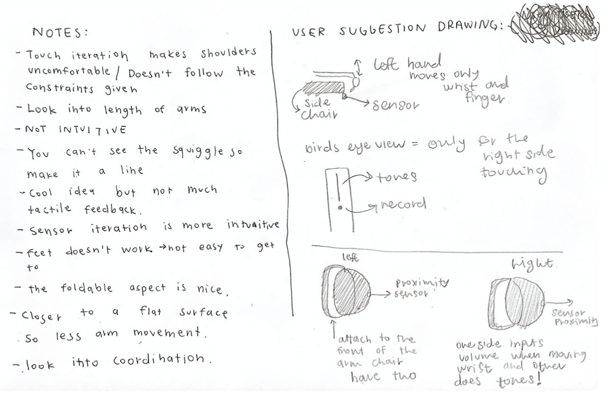
Here are the notes from the user testing.
CONCLUSION
The process was an extremely helpful learning experience as I had never worked with physical constraints in my design. In addition, coming from a communication design background, I do not know much about the product development and what is the most effective manner. I appreciate the challenges that I faced in the sense that not being able to physically work with the team and Elaine made me use my own assumtpions whether that ties with the visual or mechanical interactions.
The feedback that I got from the user testing was that the design was not as intuitive especially the touch based design. I had not thought about how the touch components are on the side of the chair, making it difficult for users to see where they are touching. They suggested moving the touch based element onto the arm rest. On the other hand, they thought that the sensor design was much more effective in the sense that the constraints work better with it.
After the presentation, we were able to talk with Elaine. It was extremely helpful to talk with her and get her input. She said that the touch base element is okay to have for the input method, but having a sensor is better for her. Her left hand works better with the manipulation of volume as it does not require much finger movement. She also enjoyed how the first design iteration was split into two inputs so that she is able to play around more with the instrument manipulation. She suggested that it is better to have the device on her arm rests but put an emphasis on not having the sensors go to the midline as she does not have the flexibility with extension. Having a plan on the arm rest is the best option for her so that she does not have to move her shoulders and arm too much while giving her arm a platform to be used as a pivot.
Based on the feedback I received, for our final device, I have a better understanding of how to move forward. I plan on choosing to incorporate Elaine’s feedback, user testers feedback, and the ergonomic exploration and findings that Connor did together to create the most effective experience.
S O F T W A R E
One of the doubts we had as a team was whether the MIDI(Musical Instrument Digital Interface) would work with the Arduino. Since it is not an inbuilt software, we were concerned about whether the connection would work and if yes, how easy and straightforward would the connection be? Another concern was whether the MIDI synthesizer would produce a sound that resembles a musical instrument enough? Or whether we needed to find a new approach. In order to answer these questions, we set up the entire MIDI connection, downloaded the appropriate software and synthesizer. To mimic an analog input, we connected a potentiometer to Arduino and by varying the value of the potentiometer, we got different pitched to be played through the synthesizer.
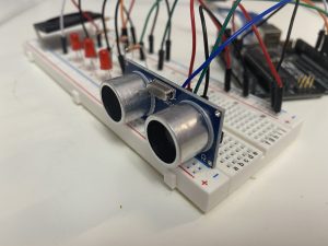
Images of the prototype
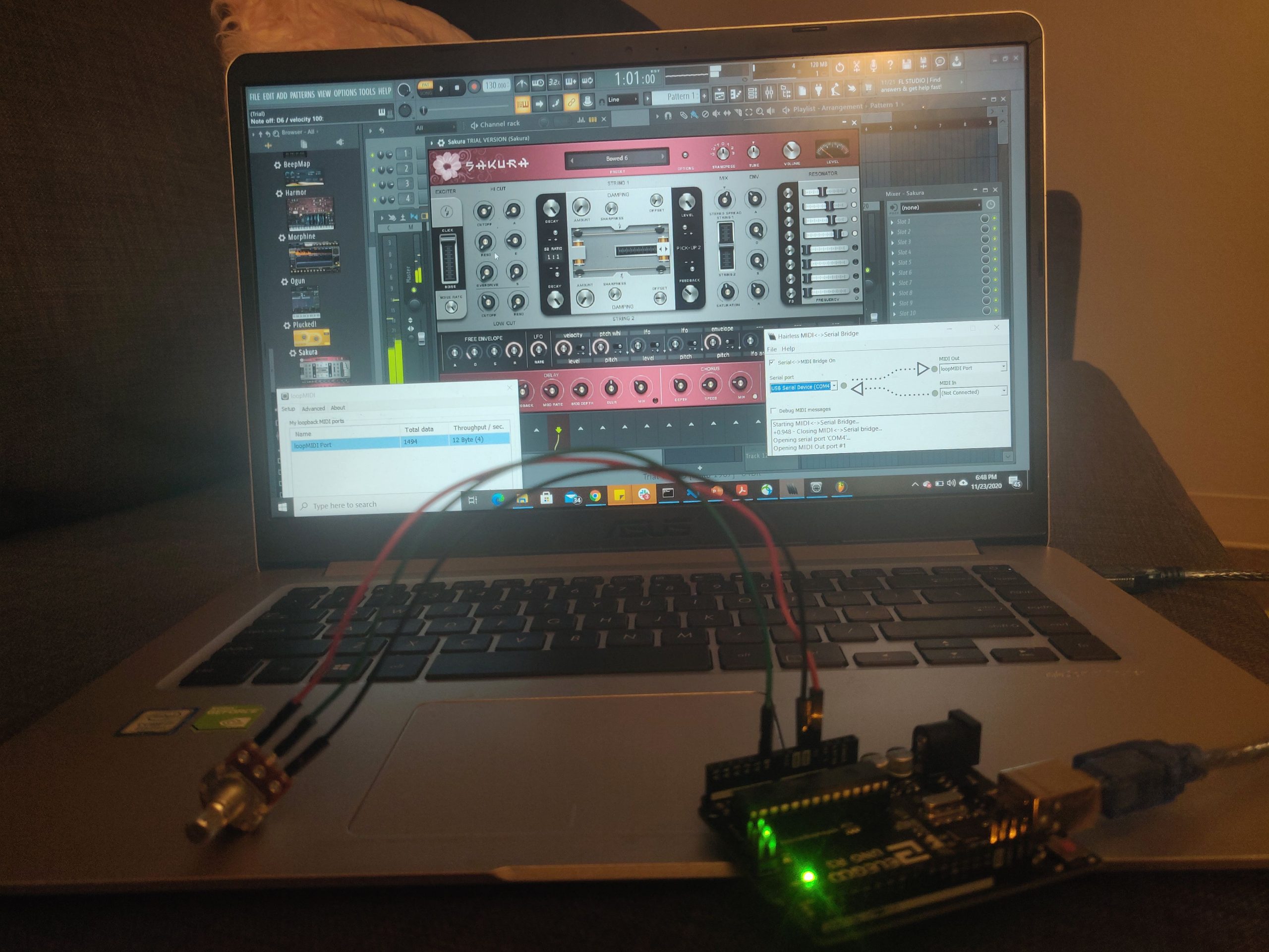
Overall prototype
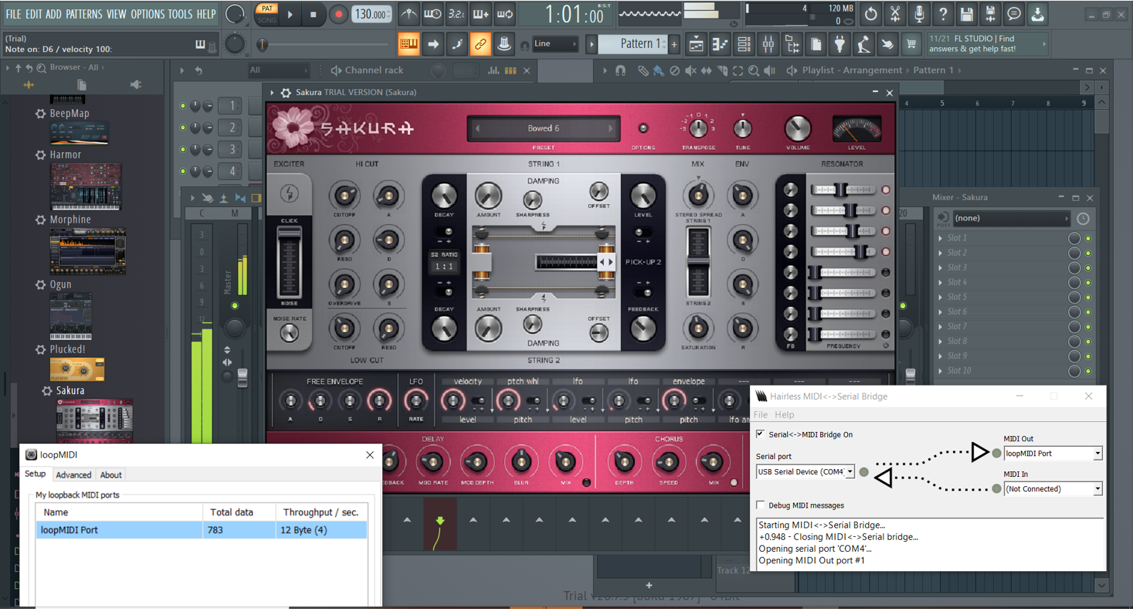
Software – music synthesizer
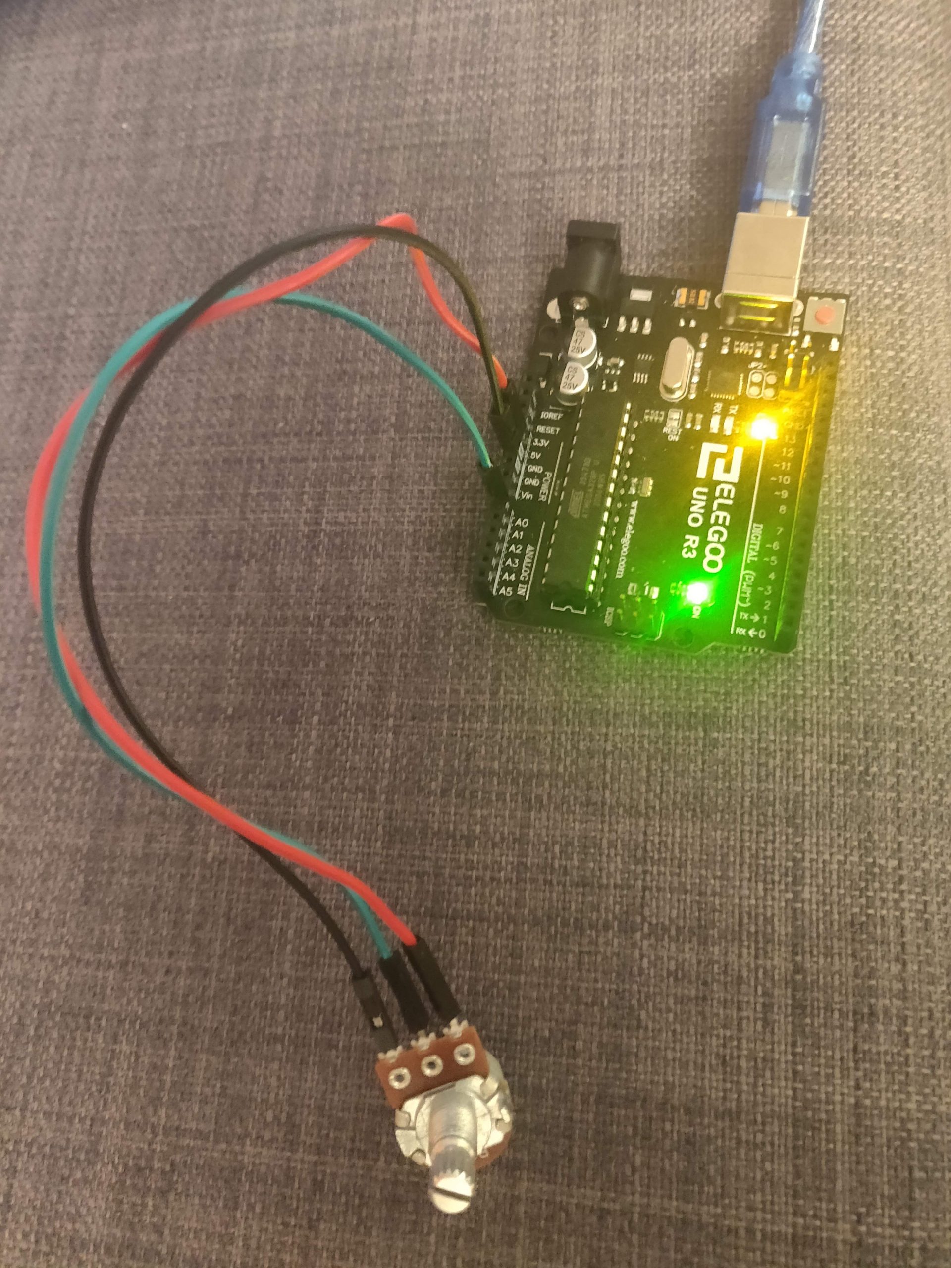
Hardware – potentiometer to simulate analog input
Video of the prototype in action
Images of in-person prototype testing
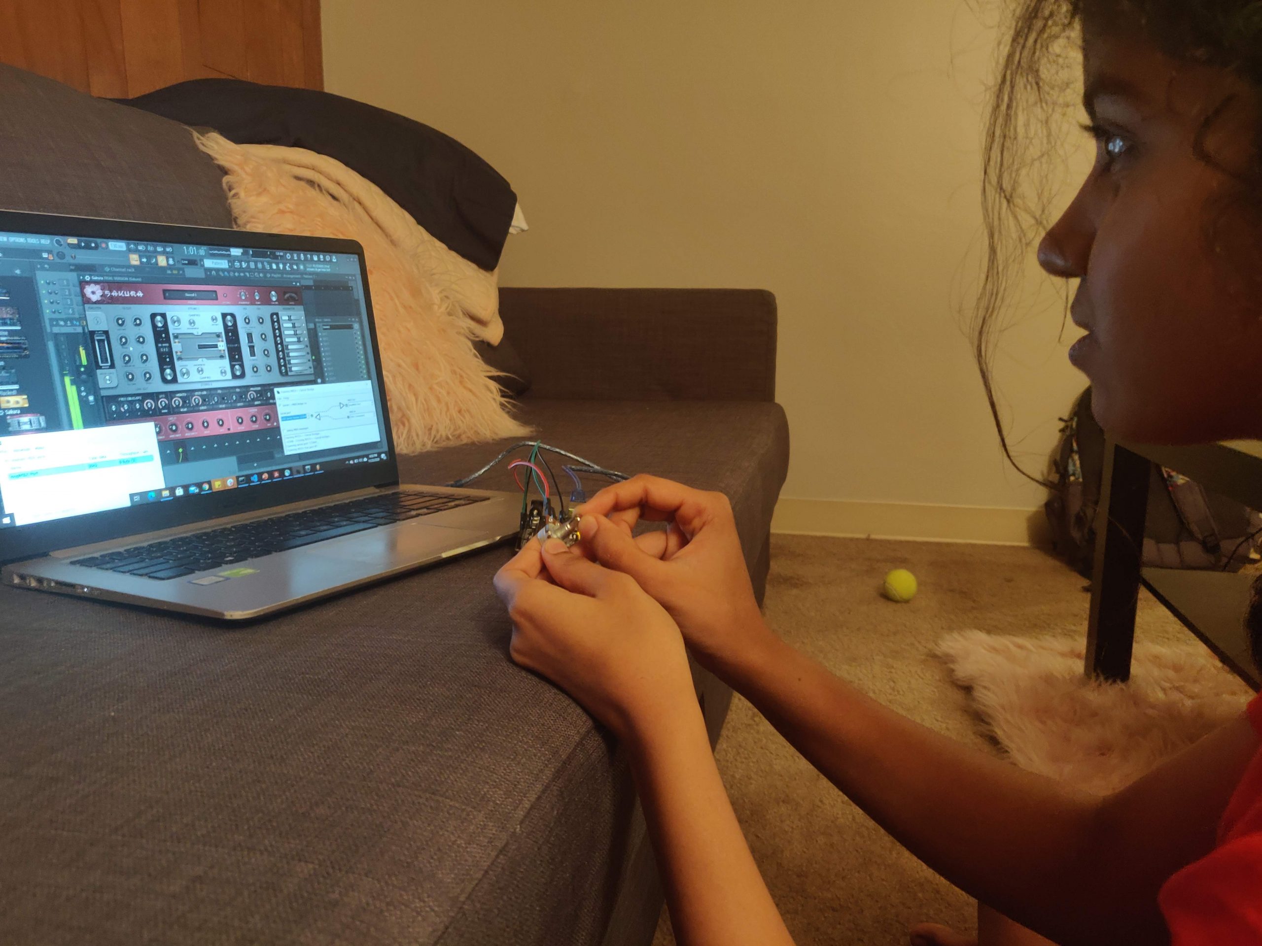
My sister testing the prototype
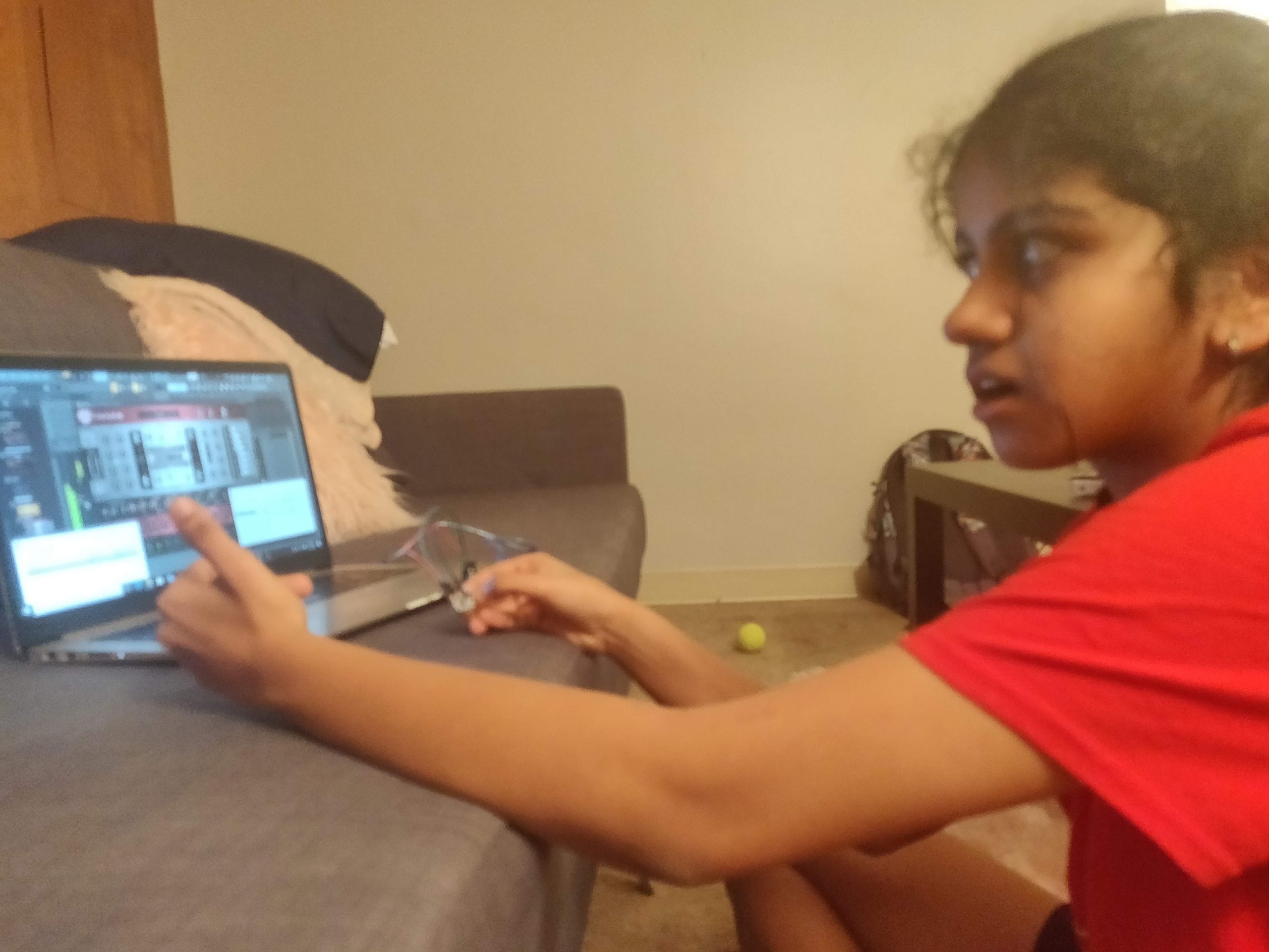
Getting feedback and suggestions on the prototype
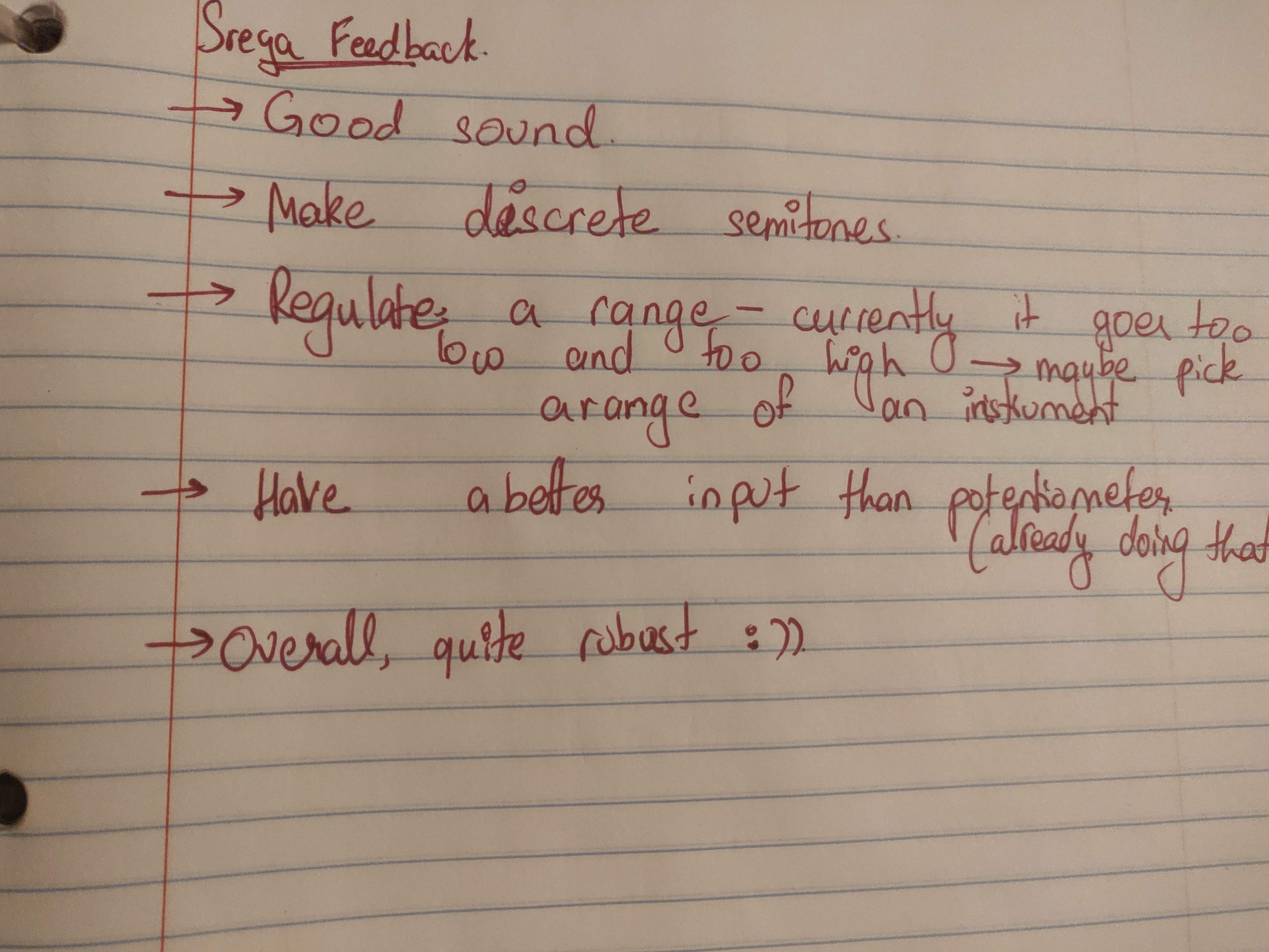
Notes taken from the testing
CONCLUSION
From my in-person prototype demo, I got very constructive and helpful feedback. This project was shown to my sister and she seemed quite impressed by the quality of sound being produced by simply rotating a small knob on the potentiometer. Overall, it did answer my question for this prototype, yes the MIDI connection works fine with the Arduino and the sound produced is very similar to that of a real instrument. My sister played around with the prototype quite a bit and came back to me with a few suggestions and modifications. One of the things she said was that I was not restricting the range of notes and so when I am trying to play a very low frequency (e.g. 10Hz), the sound is very hoarse and unpleasant. She thus asked me to restrict the frequency range of the instrument. She also suggested that I picked one instrument and research its exact range and notes and make the instrument mimic that. Another suggestion, which I would definitely love to implement, but would give a lower priority, is creating discrete notes rather than a continuous range of frequencies. This particular synthesizer already only has limited notes it can play, so it is discrete, however, she suggested I make them discrete when I pass the signal through the MIDI as it would give me control over which notes I want to let the instrument play.
While talking to Elaine about the project, she too was happy with what was done so far. In addition, however, she asked me to add a control to manipulate the volume of each note played. This is a task that is quite straightforward and doable and is a very good suggestion that will allow for more dynamic playing and makes the device more like a true musical instrument. In addition, she also asked if there was a way to choose which instrument she plays, that is vary the instrument. This is definitely possible if she manipulates the software directly but dynamically doing it through the device will be quite challenging but I hope it is possible as it a great feature to add in to the project.
Moving Forward:
Through this process, our team was able to learn a lot about what our main goals of our project is. Before we had an idea, but now, we have a strong and detailed understanding. In addition, we were able to discover the strengths and weaknesses of our prototypes to help us move forward. We used the method of “dividing and conquering” for the prototyping research was effective in allowing us to scope/answer a wider range of questions and gaps we had previously. In the end, we were able to find that ergonomic prototyping not only better mapped Elaine’s range of motion, but also pinned thresholds of comfort firsthand. The software was a lot less straightforward than expected. In addition, designing with constraints was much more difficult than expected! There would be purposeful design decisions, but the constraints weren’t fully thought out, causing issues during the user tests.
After the prototype presentations, we were able to talk with Elaine and get her feedback. It was extremely helpful because there were some aspects she really enjoyed and wanted us to continue to use while things she does not want us to have. Elaine talked about how she would love to have the device change instruments because of her past experiences of having a very limited range in band during school. In addition, having access to discreet or continuous change. As we continue to further iterate, we plan on continuing to work with Elaine to finish our project. It is extremely helpful that she has a strong background in this field so that if we have an obstacle, we are able to reach out to her and receive help.
Overall, we are able to look into new questions that were found through this exploration. Now we have three individual research directions, we are planning on using all the feedback we got to plan our next steps.
- Deciding on what type of type of interactions our device will focus on i.e touch, sensor, and mouse.
- Work on combining the software with the design prototype
- Final iteration of the prototype based on feedback
- User test with our client to get final feedback
- Musical Device is finished and reflecting on the process and potential next steps
1. Brief overall introduction for context
Following the first interview with Brenda, the first week of prototyping development saw a slow progress in our efforts to develop an adequate mechanism for our initial design concept. The mechanical nature of the foldable foot-holder that we wished to develop at first presented us with a variety of problems that we were not familiar with, and so we decided to hold a second interview with Brenda to present her our current issues and possibly to discuss new design ideas for the project.
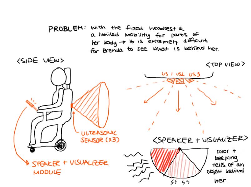
Upon completing the second interview with Brenda (full documentation on both the first and second interview could be found here), we now had a broader spectrum of ideas to choose from – some of which would require mostly electrical components than mechanical as we had hoped for. Among several different problems Brenda mentioned, the most addressable one seemed to be her inability to see behind the wheelchair – caused by the headrest that’s fixated on her chair as well as the lack of mobility in the left side of her body. She told us that she’s just learned to be careful when looking back or moving backwards.
To address this issue, we decided to make a device that would help her, to some degree, become better aware of what is behind her. Of the few possibilities for the device, we chose to incorporate a set of three ultrasonic sensors that would capture almost the entirety of her hindsight and a combination of speaker and LED lights as an output device that would provide a visual and auditory feedback for Brenda.
2. Prototype
Arleen:
This prototype was designed to help figure out the electrical composition of the device as well as experimenting with different control versions to find the most intuitive one.
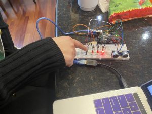
My prototype was essentially composed of purely the electrical components necessary for it to perform all its intended functionalities. More precisely, it consisted of 3 LEDs making up a visualizer corresponding to the detection device of the 3 ultrasonic sensors, a speaker for obstacle alerts, a push button for manipulating control settings, and the 3 ultrasonics for detection as mentioned earlier. While the full extent of the interaction could not be modelled by my purely electrical prototype (particularly the placement of the device parts for the most accurate results), the interactions of the different electrical parts were simulated well so interacting with one part could immediately have its impact seen on a different part (like the button control for the LEDs).
Close-up of the single ultrasonic sensor I had modeling the part of the device meant to have the arrangement of 3 ultrasonic sensors.
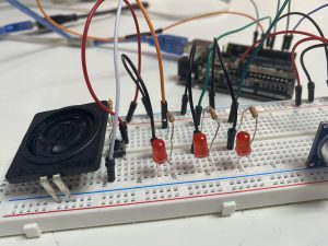
Close-up of the LED arrangements and speaker placed there modelling the alert/visualization system for the user depending on the ultrasonic sensor feedback.
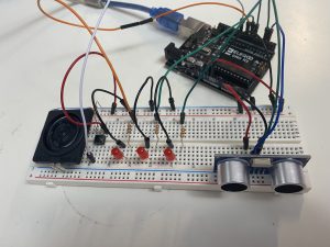
Overall scale of my prototype with all the essential electrical components mounted together.
The above is a video shot of the final button-LED visualizer mechanic based on my subject feedback for being the most intuitive version.
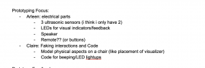
Screenshot from our planning google doc for what each of our prototypes would consist of. I built my prototype based off this initial plan.
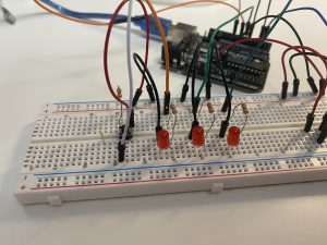
Progress stage of my prototype with only the LED lights fully wired up with the push button as well.
Picture from my feedback and testing stage with my completed prototype featuring my test subject, my mom, experimenting with different LED control mechanisms.
Before Claire and I split up the prototyping focuses, we were debating on the exact mechanism and purpose of the LED visualizer, which ended up being the highlighted focus of my prototype, as we couldn’t decide on whether having both auditory and visual feedback from the ultrasonic sensors was overkill or not. Therefore, we surmised to test whether having the visualizer indicate ultrasonic feedback or just show the active ultrasonic angle would be better. That led to my main prototype focus being on the controls of the LED visualizer, which I had my mom experiment and test for me, and she ended up giving feedback that separating out the auditory and visual feedback into different purposes (so auditory feedback would be specifically for proximity detected by the ultrasonics and the visualizer being for which ultrasonic view was active) rather than having both serve the same purpose just displaying data in different forms. While I did receive an answer that made sense in regards to my mom’s reasoning, it was rather surprising when I received the opposite feedback from Brenda in which she preferred the visual feedback from the ultrasonics, leading me to realize just how different viewpoints could be given each person’s circumstances.
Based on the feedback I received, for our end product, I chose to incorporate Brenda’s feedback as she is our client who will use this device (ideally). This meant that moving forward, my prototype did not quite end up capturing the device behavior accurately and revisions will need to be made to change the purpose and functionality of the LED visualizer feedback, in addition to the other overall feedback to improve our device design and make it even more useful and effective.
Claire:
This prototype was designed to illustrate the interaction between the person and the device as well as the general appearance and placement of the system. I focused on creating the prototype for the visual and auditory feedback-system and how it could interact with the person.
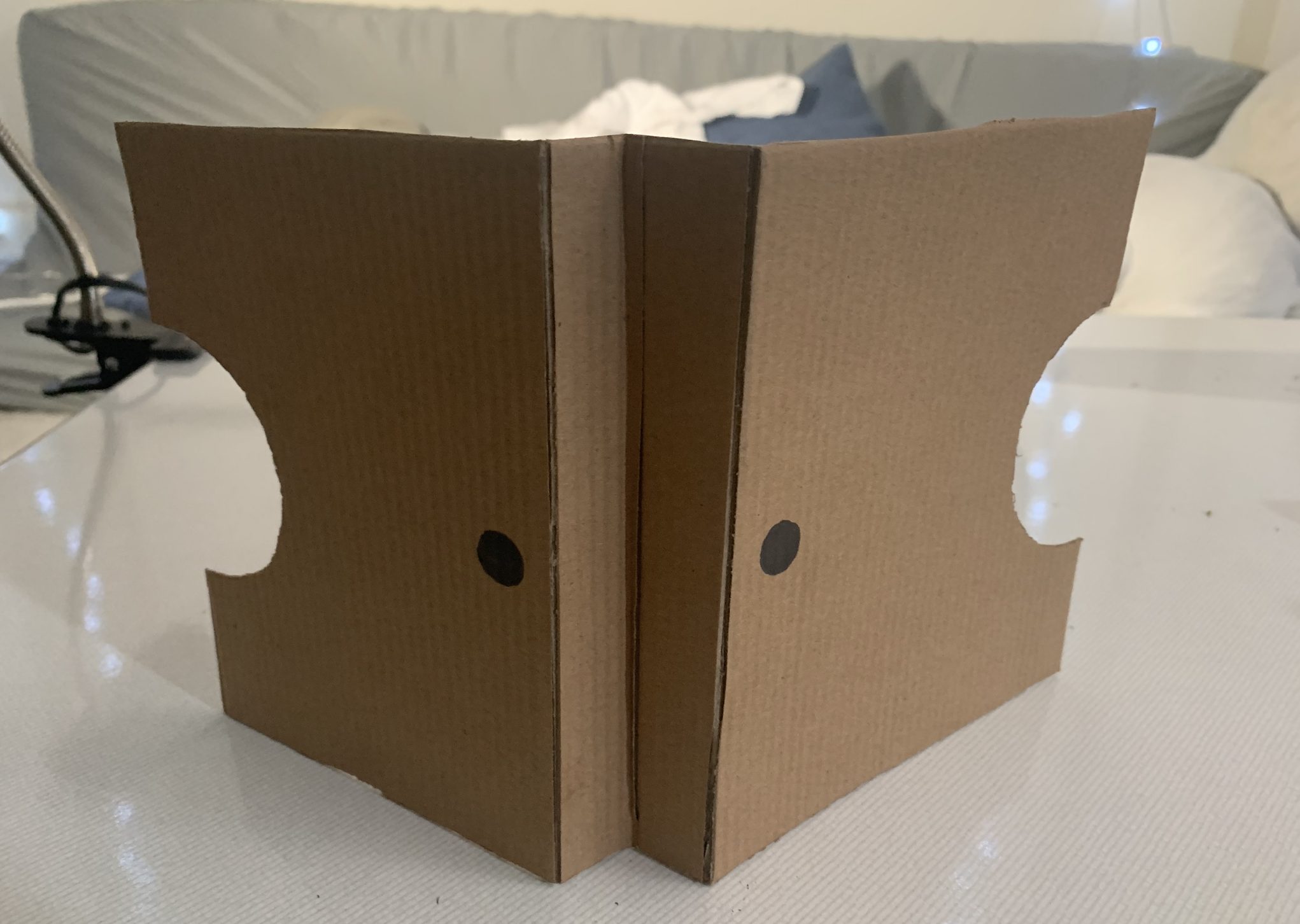
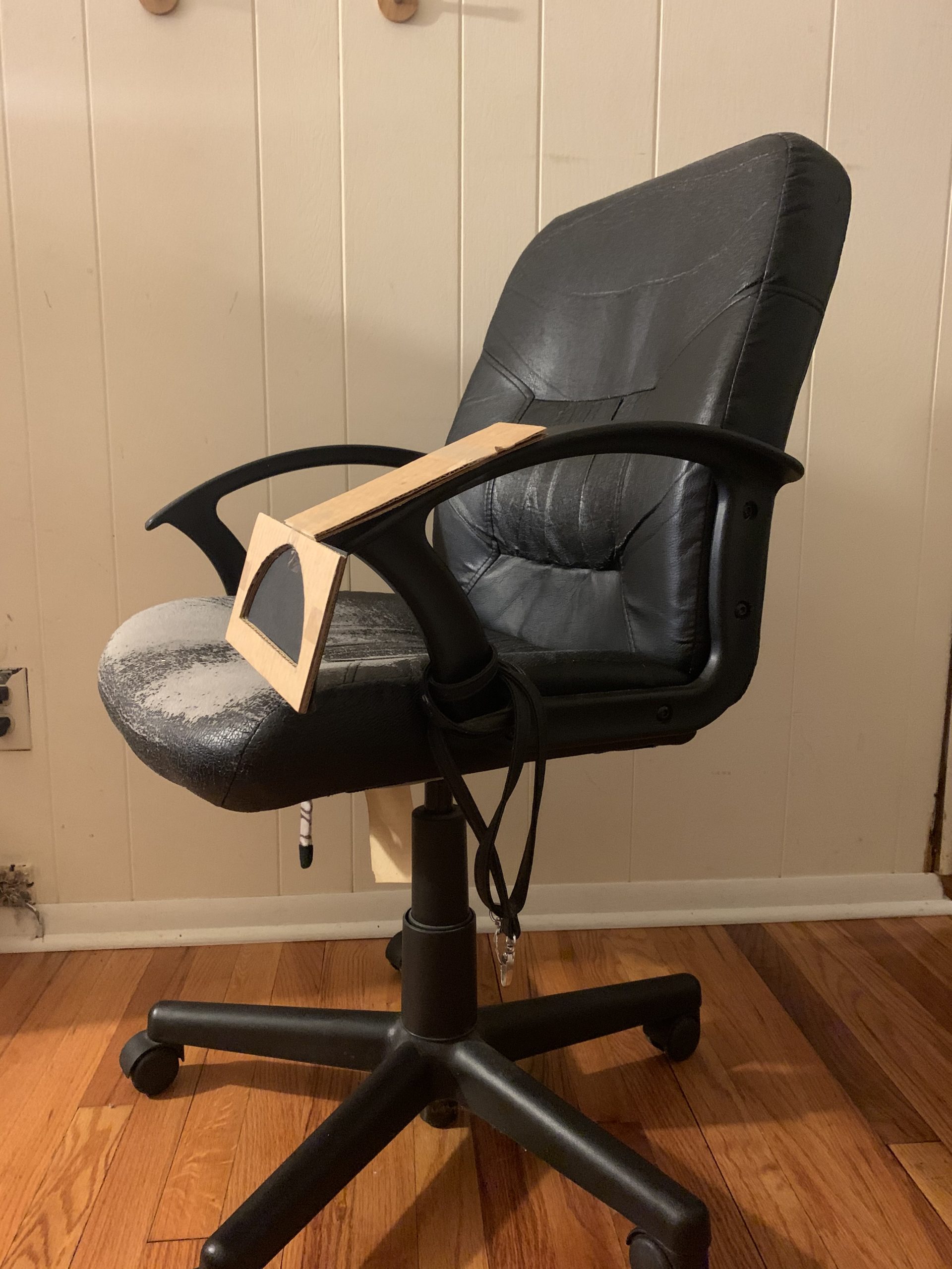
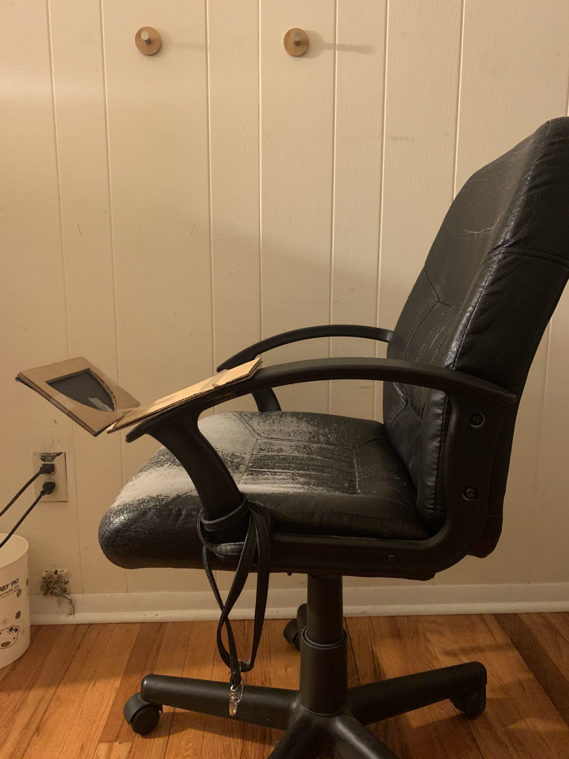
The visual + auditory feedback system (visualizer) will consist of an LED screen and a speaker. The LED screen (shown as a semicircle divided into three) in the prototype represents three distinct LED lights that will be connected to each of the three ultrasonic sensors. The speaker will be connected to the whole set of all three ultrasonic sensors. The LED will have three states: off (white), low on (pink), high on(red) – and they correspond to the proximity of the wheelchair to object(s) behind. If it’s far enough, the screen will be white; closing in, pink; very close, then red. The speaker will follow the same logic. If far, the sound will be off, closing in then slow beeping and if very close, then faster beeping.
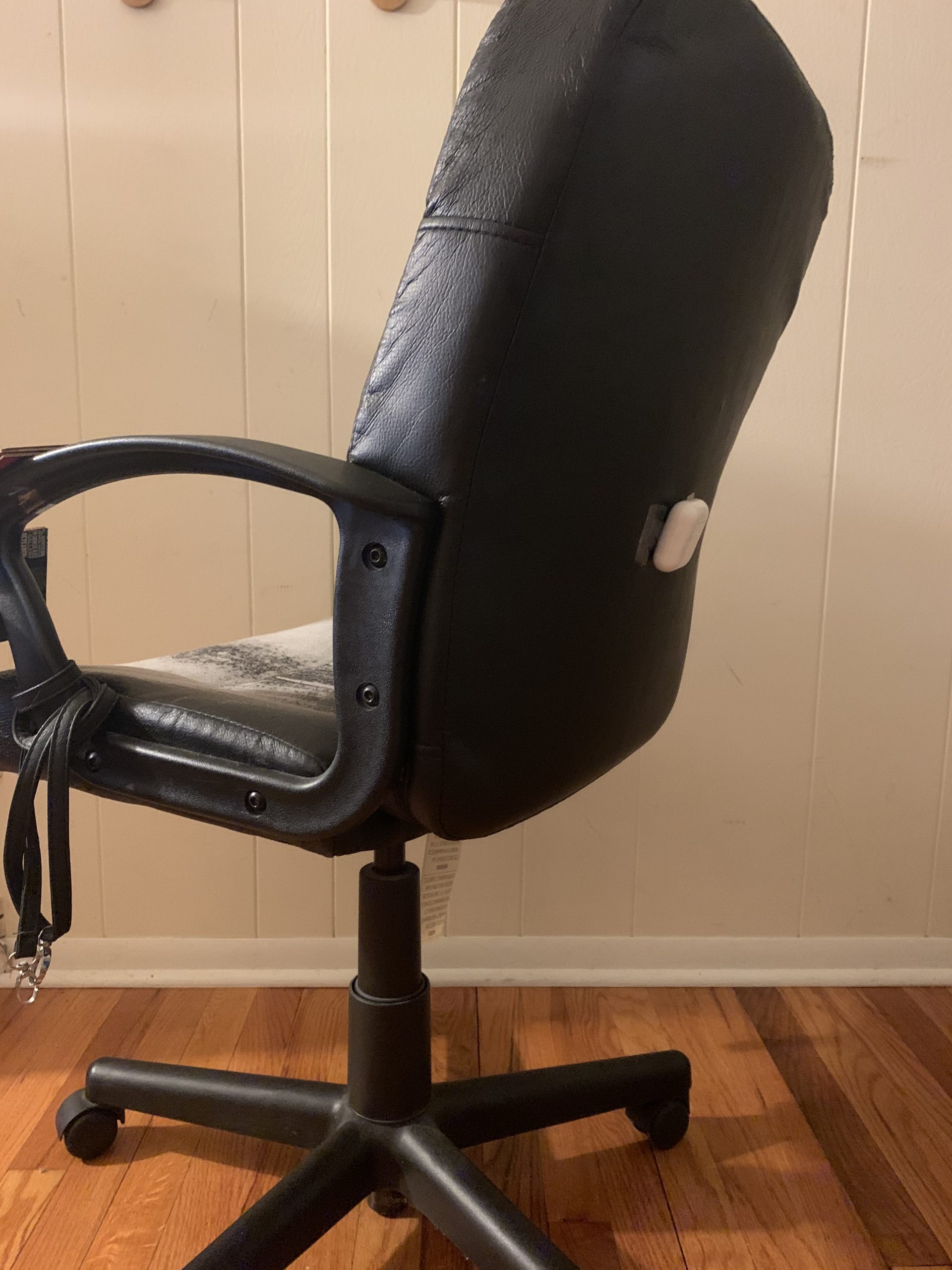
Three ultrasonic sensors will be attached on the back of the chair
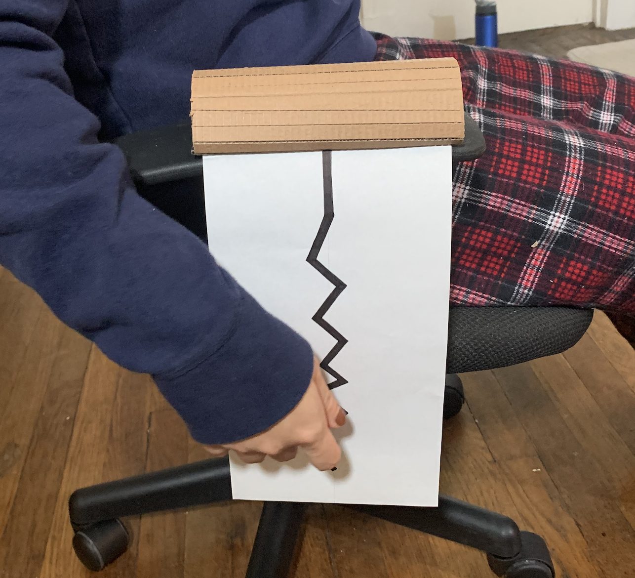
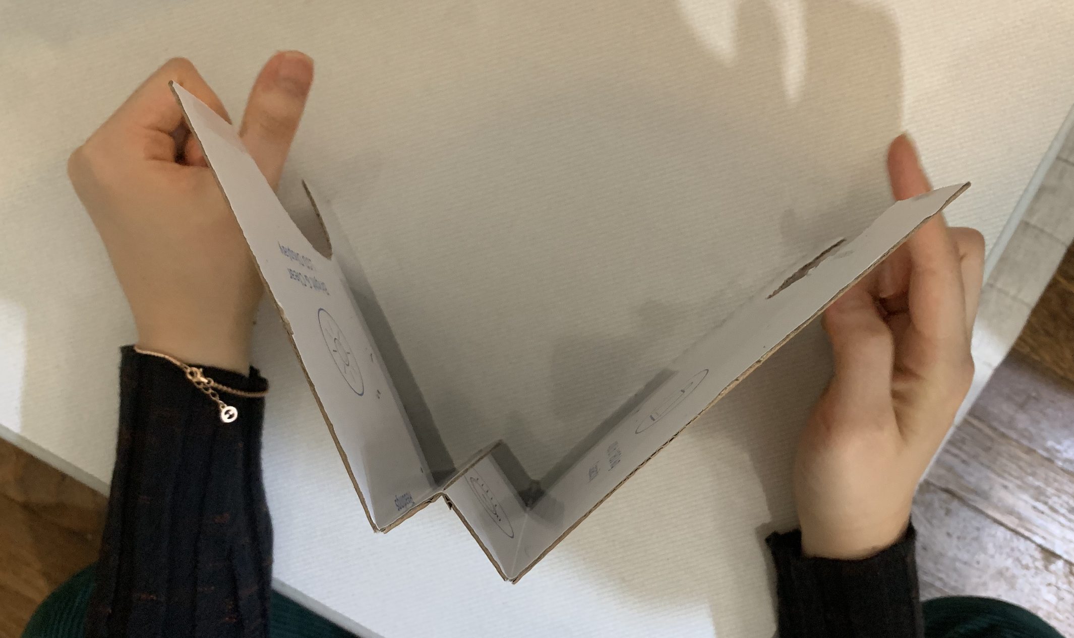
The system is at rest when the visualizer is laid off
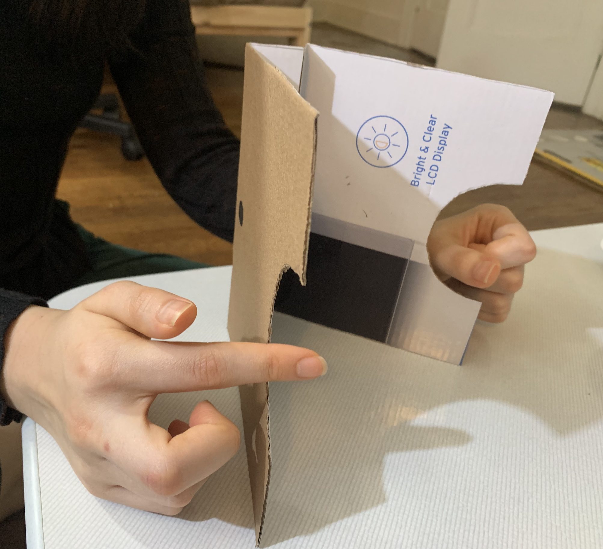
The system is activated when the visualizer is lifted
Below: process photos
Initial sketch for the device

GIF I made for the screen
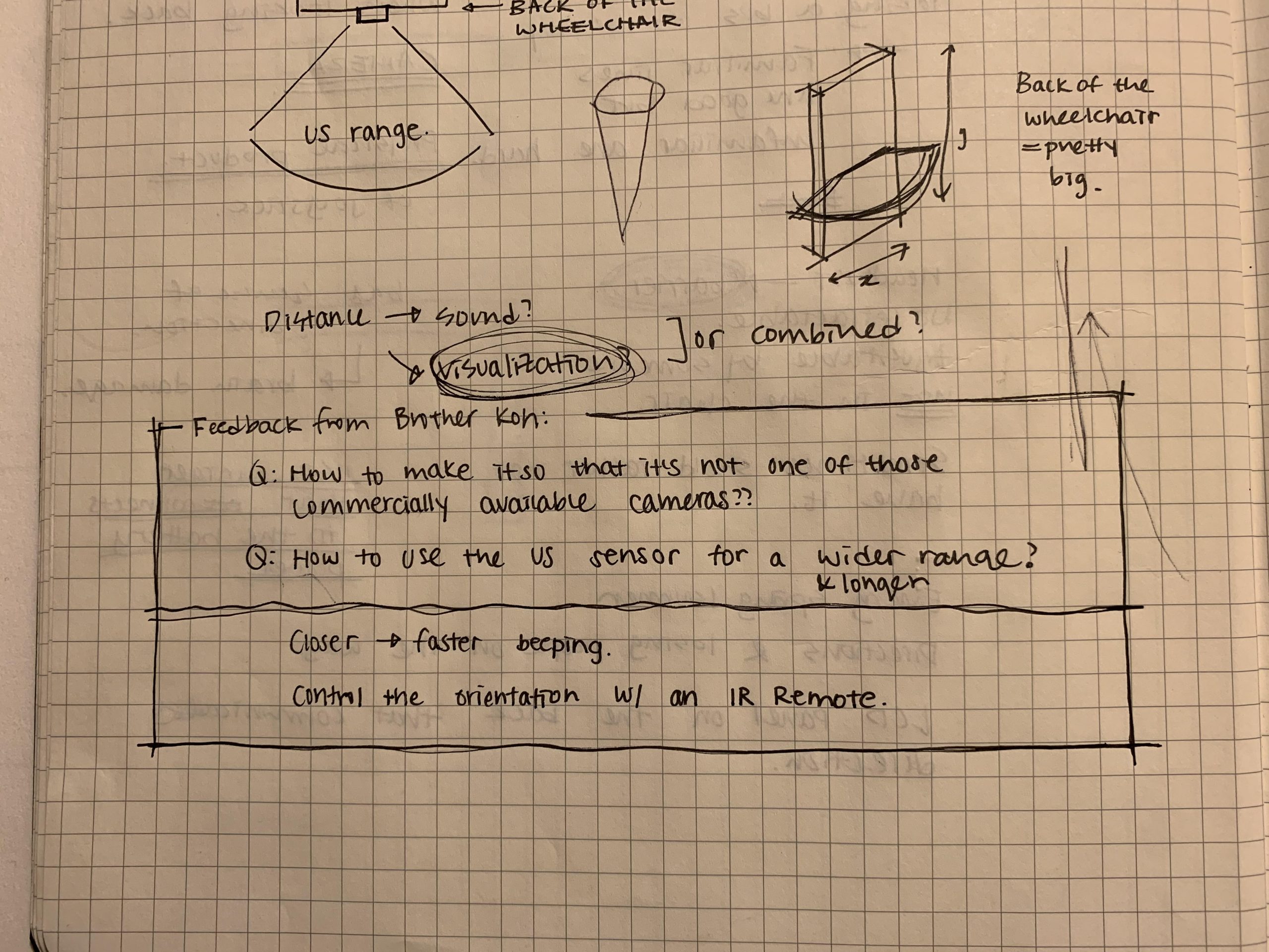
Feedback from Brother Koh
Some of the things I found while working on the physical prototype was a slight issue of an user interface. I realized that sometimes you would want to turn the device off in case you’re backing into something on purpose or if you NEED something/someone behind your wheelchair and you don’t want the device to be constantly beeping. That is why I made the system where if you lay down the visualizer, the system is deactivated and when you lift it up, it is activated. I thought about making a button for it but then realized the position of the visualizer is more recognizable and intuitive (once the visualizer is down, you won’t be able to see it so you’d know that the system has been deactivated) than a small LED light describing the on/off state or the position of the button (pressed/not pressed).
When I showed the prototype and explained it to my brother: the one thing that he kept insisting was that there is already a camera commercially available for this kind of issue. This is what inspired me to start thinking about what could be done to make the device more specific to Brenda’s problems as it will be explained later in part 3: Moving Forward.
3. Moving Forward
The prototyping process was a good way for us to discover the strengths and weaknesses of our concept as well as the drawbacks of the initial interaction design that we missed when only thinking about it theoretically. It was not until after we built the physical working prototype that we realized we need to focus more on the designing of a better user interface – make sure that the design and arrangement of parts is as intuitive as possible. Consequently, some of the future considerations include: what would be the best way to arrange the controls for easiest use? How to make the device more practical (there are already back video cameras for cars, etc. – so how to develop it more so it’s unique, and much more customized to Brenda herself?) and does more than what the commercial video cameras can already do?
Upon completing our prototype presentation and critique, we were also able to analyze the feedback we got and outline the general direction that we want to head for the next step in the project. We received more photos from Brenda that show blind spots for her wheelchair that we could address using our new device. Following are the changes we decided to implement on our design moving forward.
- Change to vibration instead of auditory beeping feedback
- Lower detection range of ultrasonic sensors to detect pets & fallen objects
- Keep version with ultrasonic sensors all active, visualizer will show which direction detects closest thing corresponding to light intensity
- Keep awareness about armrest prone to easy damage, add to inside of pocket attached to armrest instead
- Will get image of armrest area and blind spot on back of chair
- Dogs might be able to hear the ultrasonic ping and not like it – find a higher-frequency ultrasonic device.
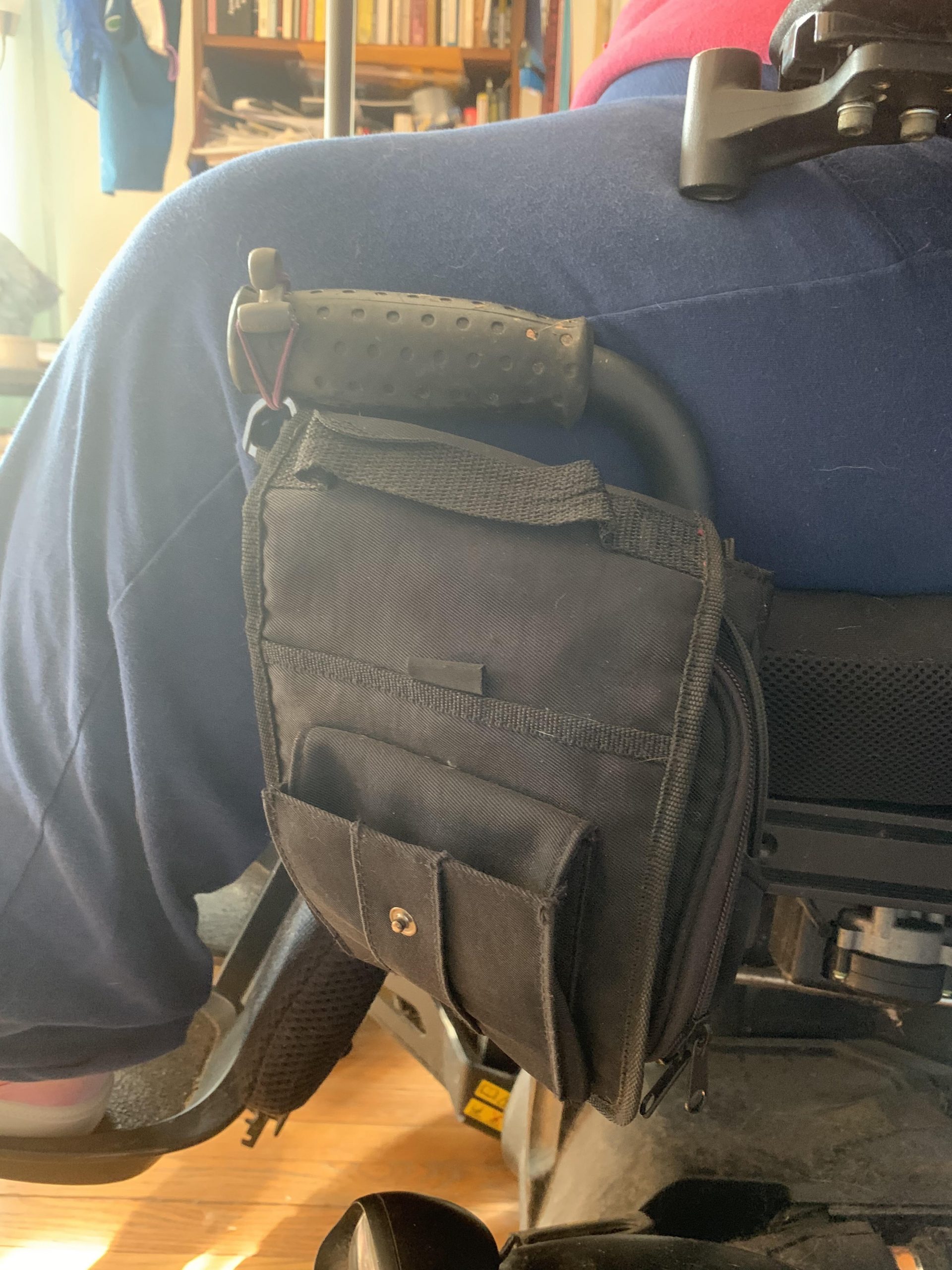
Picture from Brenda (back of her wheelchair)
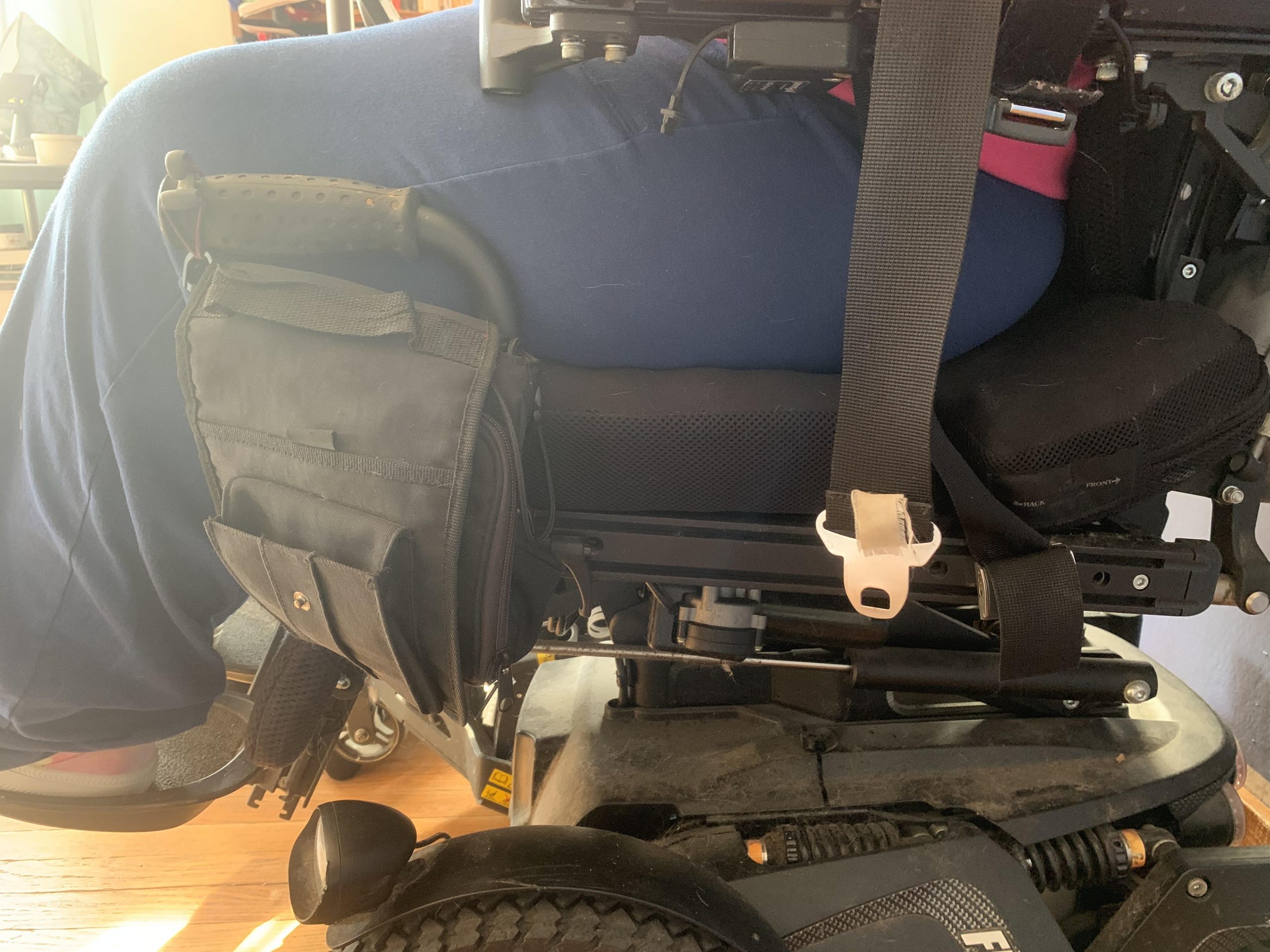
Picture from Brenda 2 (back of her wheelchair)
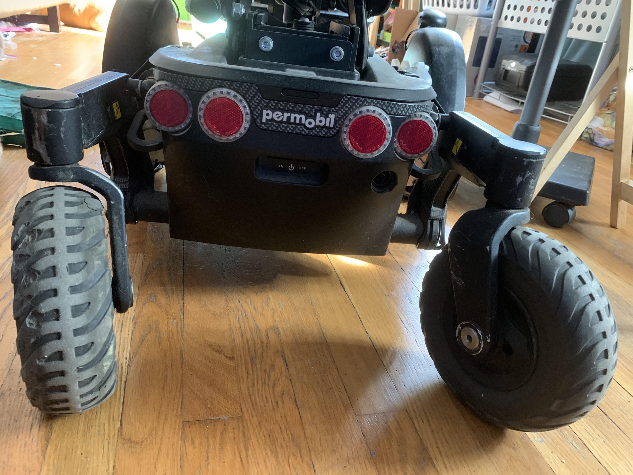
Picture from Brenda (the blind spot under her wheelchair where things/pets can get stuck
We feel hopeful about the feedback we got, the changes we decided to make and the direction we are heading towards about finalizing our concept. We believe that repurposing our concept and making a new low-range ultrasonic device that could detect pets and fallen objects will be more specific and helpful to Brenda – and it wouldn’t require us to change too much of our initial concept and is perfectly within our ability to produce.
]]>