Title: Distance – Color – Sound Pitch Double Transducer

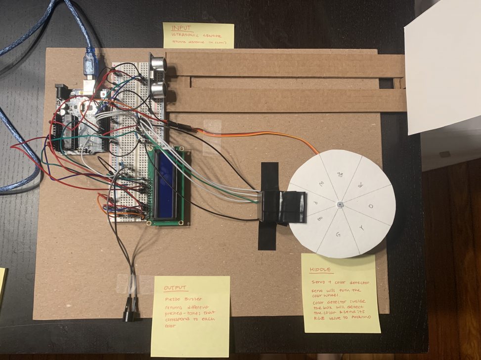
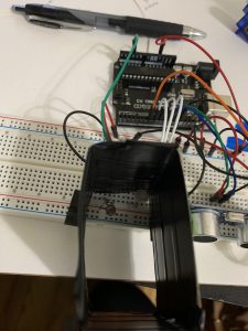
1. Final
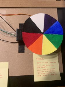
2. Underside of the color wheel
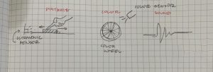
Description: The project will take the distance measured by the ultrasonic sensor as an input, map the data to the rotational angle of servo which corresponds to different colors. The color sensor will then recognize the color that sits right above itself and output its R,G,B values. Arduino will then map the R value of the color to the pitch of the sound coming from the speaker.
Progress: We initially had three ideas. The first one was Distance – Voltage – Sound Pitch, second one was Distance – Light Intensity – Sound Pitch, and the third one was the aforementioned Distance – Color – Sound Pitch scheme.
The first option seemed most interesting to us so at first we decided to go with that, but in case it doesn’t work out we also decided to start working on the third scheme as a backup plan.
Unfortunately, we couldn’t figure out how to work the generator within a reasonable amount of time – and so decided to go with the Distance – Color – Sound Pitch scheme. Turned out though, that wire was wrapped with a thin coat of enamel and we had to peel off its ends before connecting to other wires.
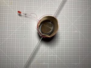
The way this was going to work was a conductive material was going to be wrapped around a cylinder. The cylinder was to ensure the proper spacing within the magnetic field to enable the voltage to be generated. A thin rod was going to be pushed through a small hole in the tube with two magnets attached to the rod. In order to ensure the magnets stayed in place, two spacers were placed between the disc magnets and all of it was glued together.
Side view of the generator. There are two magnets attached separated by two semicircles of foam.
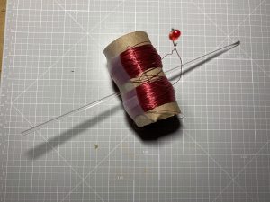
Top view of the generator. Shows the 400 total wrappings of wire and the red LED attached. The clear rod is what is used to spin the magnet inside of the tube.
The design was inspired by a YouTube video by Prof. Melloch (https://www.youtube.com/watch?v=O5n6ubrbK5A&list=WL&index=38). The video describes this technique and shows the generator powering an LED. Because the generator produces an alternating current, the board system would need to be wired such that the one end of the wire goes into the ground and the other end goes into a diode which goes into the arduino board. How this was going to work was the distance from the ultrasonic sensor was going to then be turned into a value that was going into the DC motor as a speed, to turn it in one direction.The voltage amount could then be read and depending on the levels produced, would go towards the pitch. The closer the object, the faster the speeds, the higher the pitch. Move the object away, the speed will slowly decrease causing the pitch to get lower.
Back to the Distance – Color – Sound Pitch scheme
For mapping the distance, we used the ultrasonic sensor and the NewPing library to measure the distance between the sensor and the slider (made with a cardboard track along which you could move the paper panel). For outputting sound we used the piezo buzzer and the tone() function.
More importantly this scheme required a color sensor – which wasn’t present in the Ideate Lab or the course kit – so we had to make one on our own! We referred to this website (https://www.instructables.com/Using-an-RGB-LED-to-Detect-Colours/) to make one using an RGB LED and a photoresistor.
This color sensor was based on the fact that objects of certain colors will absorb the lights with the corresponding color spectrum. Red will absorb red lights, green will absorb red lights, and blue will absorb blue lights. And as a result, the intensity of the light when shone on a colored object will be less than when it’s shone on a white object (because these colors will absorb some of the lights whereas white would reflect all of them). Similarly, the intensity of the returning light shone on a black object will be lower than any other colored or white objects.
So if we could measure the intensity of the lights returned by the black object and the white object, we could use them as a baseline to determine the color of the object that’s placed after.
Following this idea we made a little container that would house the RGB LED light and a photoresistor where the colored object could be placed on top. The RGB LED will constantly blink red green and blue lights and each time it blinks the photoresistor will measure the light intensity of the returning red, green, and blue lights (after being shone to the object). We included the math in the code that would then translate this to the R, G, B values.
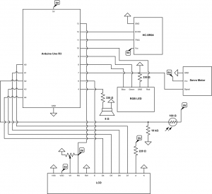
Circuit Lab schematic. Custom parts were created in order to fulfill the space for the LCD, RGB LED, Servo Motor, and the Ultrasonic Sensor.
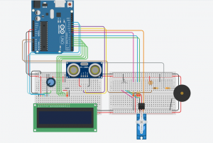
TinkerCad URL: https://www.tinkercad.com/things/5mjYhZFEZLF-smashing-turing/editel?sharecode=Hx0GhsKUVg7Llu1k5vD2kHo5FLbbgOpP2zSBgdz99OI
First attempt at making the color sensor
Testing blue and red (note the RGB values on the serial monitor – pretty accurate!)
Final Videos:
Video Part 1: Calibration (color sensor measures the light intensity of white then black)
Video Part 2: Double transducer at full work. The system automatically calibrates itself then starts working – split the video in half to upload them faster.
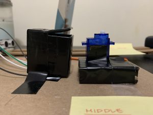
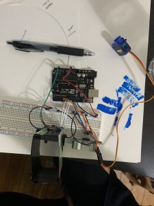
1. servo + color sensor combo.
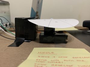
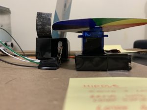
2. how the color wheel fits on the servo and the color sensor
3. showing the inside of the color sensor (the shell is made of cardboard + black electrical tape to block out ambient light. On the inside there’s the RGB LED and a photoresistor)
Discussion: We were able to wire the individual components together relatively early in the project – US sensor to servo was working fine, and the color wheel to pitch was working fine.
The problem developed when we were trying to connect the US sensor + servo part to the color wheel + pitch part. Upon compiling the code we kept getting the error that said:
Collect2.exe: error: 1d returned 1 exit status
Exit status 1
Error compiling for board Arduino Uno.
Multiple definition definition of __vector 11_’
After an extensive research that took hours on end, we found out that it is because multiple devices were trying to use the same internal timer on Arduino. In this case, the tone() function and the NewPing Library were both using Timer 2.
So what we decided to do was use a different tone function library – we found a couple called NewTone(), ToneAC(), and ToneAC2() that would provide the same result as a regular tone() function.
But to our surprise (Not even at this point – seemed like everything that could go wrong was going wrong) this time, these new tone libraries were using Timer 1, which was the same timer that the servo library was using and we got this error message:
Collect2.exe: error: 1d returned 1 exit status
Exit status 1
Error compiling for board Arduino Uno.
Multiple definition definition of __vector 7_’
Extremely frustrated, I started looking for libraries that did not use the timer that could replace either the NewPing, servo or the tones() mentioned above. And I came upon this thing called TimerFreeTone library – which did not use the timer! But when I ran the code the speaker didn’t make a continuous sound – it just beeped for a little after the Arduino had run all the other functions than the TimerFreeTone. And because there was a delay between the tones while the color wheel was moving – the pitch wasn’t really updating on time.
I later noticed that all the explanations that were posted online said the NewPing ‘LIBRARY’ used the Timer – so I wondered if you had written the code yourself the tone() would work. And we did come upon a post that said both would work at the same time if you wrote the US sensor code from scratch after which we did write the code for the US sensor ourselves with the help from (https://create.arduino.cc/projecthub/Isaac100/getting-started-with-the-hc-sr04-ultrasonic-sensor-036380) and it worked!
Another minor problem we had came from the color sensor. It’s a makeshift color sensor so the RGB values that we were getting weren’t perfect. Even when the servo wasn’t rotating the pitch kept shifting a little (though within a small range). The fact that we painted the color wheels ourselves and the coat wasn’t consistently thick could have also contributed to this. But once you waited a little the pitch became relatively stable. Also we noticed that the servo wasn’t quickest to react at times – which made . We experimented with inserting and deleting delays at certain parts of the code and at the end it was working pretty smoothly.
Other issues were derived from working with the L293D component towards the early stages of the design prototyping process. It was more a function of figuring out how to properly wire a motor to it to ensure the desired outcome. With trial and error, we were able to figure it out without pulling out too many hairs. The main source of this was derived from finding a model that only had one motor versus two motors attached to the L293D chip. We experienced an error that was saying there was a power imbalance for the chip and I did not know what that meant. But again, trial and error and looking for references to consult, we succeeded.
The LCD was also not cooperating perfectly during testing. We were finding some of the characters being displayed were not even English. This created quite the havok as we were attempting to resolve one issue after the other just to get a general gauge of where we were in the project. Like all things, after consulting Google for a little, we found a source that was saying the LCD sometimes just needs to be unplugged and plugged back in, a simple solution to almost every electronics problem.
Code:
/*
* Project 1
* Claire Koh, Carl Young
* two weeks
*
* Collaboration: Between Claire Koh and Carl Young
* RGB LED & Photoresistor Color sensor tutorial from:
* https://www.instructables.com/Using-an-RGB-LED-to-Detect-Colours/
* Ultrasonic Sensor code from scratch:
* https://create.arduino.cc/projecthub/Isaac100/getting-started-with-the-hc-sr04-ultrasonic-sensor-036380
*
* Challenge: Timer Issue: NewPing Library, Servo Library and Tone() function all use Arduino Timer
* Tone() and NewPing use Timer 2
* NewTone(), ToneAC, ToneAC2 and Servo uses Timer 1
* TimerFreetone doesn’t let out continuous tone
* Solution: Wrote the NewPing code from scratch instead of using NewPing to get rid
* of the timer conflict
*
* RGB LED + Photoresistor Color Detector wasn’t perfect
* – wasn’t able to get the perfect RGB values
* but they were relatively in range and did change according to the colors
* Solution: mapped the value to 0-255. Wait it out and the pitch becomes pretty consistent
* Servo – sometimes isn’t the quickest to react. Needs time to rotate
* Solution: delays or no delays at right spots
*
* Next time: We won’t be running into these timer problems
* because now we know which library uses which timer.
* We will also try a little bit harder to find out why the
* generator was not working to hopefully not give up on an
* idea too quickly.
*
* Description: The code below uses the ultrasonic sensor to
* map the distance between itself and a movable panel
* which will be mapped to the servo angle that turns the color wheel
* that is placed on top of the color wheel
* Then the color sensor will read the RGB values of the color
* placed directly on top of it
* Ardiuino will then translate the R value to the pitch of the sound
* coming from the piezo buzzer.
*
* Pin mapping:
*
* pin | mode | description
* ——|——–|————
* A0 output D7 pin LCD
* A1 output D6 pin LCD
* A2 input Photoresistor pin
* A3 output D5 pin LCD
* A4 output D4 pin LCD
* 4 output piezo buzzer
* 6 output Enabling pin LCD
* 7 output servo
* 8 output Blue for RGB LED
* 9 output Green for RGB LED
* 10 output Red for RGB LED
* 11 output Trigger Pin for Ultrasonic sensor
* 12 input Echo Pin for Ultrasonic sensor
* 13 input Register Select pin LCD
*
*/
#include <Servo.h>
#include<LiquidCrystal.h>
// System 1 Pins
const int TRIGGER_PIN = 11; // Arduino pin tied to trigger pin on the ultrasonic sensor.
const int ECHO_PIN = 12; // Arduino pin tied to echo pin on the ultrasonic sensor.
const int MAX_DISTANCE = 30; // Maximum distance we want to ping for (in centimeters). Maximum sensor distance is rated at 400-500cm.
// System 2 Pins
const int R_LED_PIN = 10;
const int G_LED_PIN = 9;
const int B_LED_PIN = 8;
const int SERVO_PIN = 7;
const int PHOTORESISTORPIN = A2;
// System 3 Pins
const int SPEAKER_PIN = 4;
// LCD Pins
const int RSPIN = 13;
const int EPIN = 6;
const int D4PIN = A4;
const int D5PIN = A3;
const int D6PIN = A1;
const int D7PIN = A0;
const unsigned long WAIT = 500;
unsigned long timer;
int inVal, outVal;
int ledArray[] = {R_LED_PIN,G_LED_PIN,B_LED_PIN};
boolean balanceSet = false;
int red = 0;
int green = 0;
int blue = 0;
long colorArray[] = {0,0,0};
long whiteArray[] = {0,0,0};
long blackArray[] = {0,0,0};
int avgRead;
long duration;
long distance;
Servo servoMotor;
LiquidCrystal lcd(RSPIN,EPIN,D4PIN,D5PIN,D6PIN,D7PIN);
void setup() {
Serial.begin(115200);
Serial.setTimeout(50);
lcd.begin(16,2);
lcd.setCursor(0,0);
lcd.print(“i:”);
lcd.setCursor(6,0);
lcd.print(“m:”);
lcd.setCursor(12,1);
lcd.print(“o:”);
pinMode(R_LED_PIN, OUTPUT);
pinMode(G_LED_PIN, OUTPUT);
pinMode(B_LED_PIN, OUTPUT);
pinMode(PHOTORESISTORPIN, INPUT);
pinMode(TRIGGER_PIN,OUTPUT);
pinMode(ECHO_PIN,INPUT);
pinMode(SERVO_PIN, OUTPUT);
pinMode(PHOTORESISTORPIN, INPUT);
pinMode(SPEAKER_PIN, OUTPUT);
servoMotor.attach(SERVO_PIN);
}
void loop() {
checkBalance();
checkColor();
printColor();
// Clears the trigPin condition
digitalWrite(TRIGGER_PIN, LOW);
delayMicroseconds(2);
// Sets the trigPin HIGH (ACTIVE) for 10 microseconds
digitalWrite(TRIGGER_PIN, HIGH);
delayMicroseconds(10);
digitalWrite(TRIGGER_PIN, LOW);
// Reads the echoPin, returns the sound wave travel time in microseconds
duration = pulseIn(ECHO_PIN, HIGH);
// Calculating the distance
distance = (duration * 0.0342) / 2; // Speed of sound wave divided by 2 (go and back)
Serial.println(distance);
if(distance>=MAX_DISTANCE){ // Caps the value for distance at 200
distance = MAX_DISTANCE;
}
//delay(400);
//int realdistance = map(distance, 0, , 0, MAX_DISTANCE);
//int realdistance = map(distance, 0, 255, 0, MAX_DISTANCE);
//LCD PRINTING FOR THE ULTRASONIC SENSOR
int newDist = map(distance,0,MAX_DISTANCE,0,99);
if(newDist<10){
lcd.setCursor(2,0);
lcd.print((String)”0″+newDist);
}
else{
lcd.setCursor(2,0);
lcd.print(newDist);
}
//Maps the distance to the servo angle
int servoangle = map(distance, 0, MAX_DISTANCE, -180, 180);
servoMotor.write(servoangle);
//LCD PRINTING FOR THE COLOR WHEEL (1)
int newAngle = map(servoangle,-180,180,0,99);
if(newAngle<10){
lcd.setCursor(8,0);
lcd.print((String)”0″+newAngle);
}
else{
lcd.setCursor(8,0);
lcd.print(newAngle);
}
//if (colorArray[0] <= 0) {
//colorArray[0] = 0;
//}
// LCD PRINTING FOR THE COLOR WHEEL (2)
int realColor = map(colorArray[0], -500, 500, 0, 255);
int newColor = map(realColor,-500,500,0,99);
if(newColor<10){
lcd.setCursor(8,1);
lcd.print((String)”0″+newColor);
}
else{
lcd.setCursor(8,1);
lcd.print(newColor);
}
int pitch = map(realColor, 0, 255, 200, 800);
tone (SPEAKER_PIN, pitch);
//delay(100);
//LCD PRINTING FOR THE SPEAKER
int newPitch = map(pitch,200,800,0,99);
if(newPitch<10){
lcd.setCursor(14,1);
lcd.print((String)”0″+newPitch);
}
else{
lcd.setCursor(14,1);
lcd.print(newPitch);
}
Serial.println((String)”newDist: “+newDist);
Serial.println((String)”newColor: “+newColor);
Serial.println((String)”newAngle: “+newAngle);
Serial.println((String)”newPitch: “+newPitch);
Serial.println(newPitch);
}
//For MQTT Monitor
if (millis() – timer > WAIT) {
outVal = newPitch;
//transmitSerialSignal();
timer = millis();
}
void checkBalance() { //check if the balance has been set, if not, set it
if (balanceSet == false) {
setBalance();
}
}
void setBalance() {
//set white balance
servoMotor.write(0);
delay (5000); //delay for five seconds, this gives us time to get a white sample in front of our sensor
//scan the white sample.
//go through each light, get a reading, set the base reaing for each color red, green, and blue to the white array
for (int i = 0; i<= 2; i++){
digitalWrite(ledArray[i], HIGH);
delay(100);
getReading(5); //number is the number of scans to take for average, this whole function is redundant, one reading works just as well.
whiteArray[i] = avgRead;
digitalWrite(ledArray[i], LOW);
delay(100);
}
//done scanning white, now it will pulse blue to tell you that it is time for the black (or grey) sample.
//set black balance
servoMotor.write(50);
delay (5000); // wait for five seconds so we can position our black sample
// go ahead and scan, sets the color values for red, green, and blue when exposed to black
for (int i = 0; i <=2; i++){
digitalWrite(ledArray[i], HIGH);
delay(100);
getReading(5);
blackArray[i] = avgRead;
digitalWrite(ledArray[i],LOW);
delay(100);
}
balanceSet = true;
delay(5000); //delay another 5 seconds to let us catch up
}
void checkColor() {
for (int i =0; i<=2; i++){
digitalWrite(ledArray[i],HIGH); //turn on the LED, red, green or blue depending which iteration
delay(100);
getReading(5);
colorArray[i] = avgRead; //set the current color in the array to the average reading
float greyDiff = whiteArray[i] – blackArray[i];
//the highest possible return minus the lowest returns the area for values in between
colorArray[i] = (colorArray[i] – blackArray[i])/(greyDiff)*255;
//the reading returned minus the lowest value divided by the possible range multiplied by 255
//will give us a value roughly between 0-255 representing the value for the current reflectivity
//(for the color it is exposed to) of what is being scanned
digitalWrite(ledArray[i],LOW); //turn off the current LED
delay(100);
}
}
void getReading(int times){
int reading;
int tally = 0; //take the reading however many times was requested and add them up
for (int i = 0; i<times; i++){
reading = analogRead(PHOTORESISTORPIN);
tally = reading + tally;
delay(10);
}
//calculate the average and set it
avgRead = (tally)/times;
}
//prints the color in the color array, in the next step, we will send this to processing to see how good the sensor works.
void printColor(){
Serial.print(“R=”);
Serial.print(int(colorArray[0]));
Serial.print(“G=”);
Serial.print(int(colorArray[1]));
Serial.print(“B=”);
Serial.println(int(colorArray[2]));
}
void serialEvent(){
/* You do *not* need to call this function in your loop;
it is a special function that will run whenever serial
data flows into the Arduino. */
/* The function assumes your machine’s input value
is called “inVal” (change that variable name as needed) */
//For MQTT Monitor
//If there is incoming serial data, read it
while (Serial.available() > 0){
// interpret incoming digits as integer and save into inVal
inVal = Serial.parseInt();
}
}